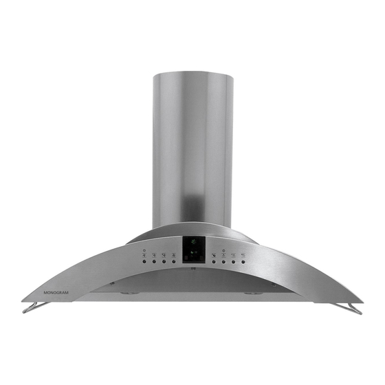
GE Monogram ZV750 Technical Data Sheet
36" wall-mounted hood
Hide thumbs
Also See for Monogram ZV750:
- Installation instructions manual (56 pages) ,
- Owner's manual (32 pages) ,
- Technical service manual (30 pages)
Advertisement
Quick Links
MONOGRAM 36" WALL-MOUNTED HOOD
IMPORTANT SAFETY NOTICE
ThIS INFORMATION IS INTENdEd FOR uSE bY
PERSONS POSSESSINg AdEquATE bACkgROuNdS
OF ElECTRICAl, ElECTRONIC ANd MEChANICAl
ExPERIENCE. ANY ATTEMPT TO REPAIR A MAjOR
APPlIANCE MAY RESulT IN PERSONAl INjuRY ANd
PROPERTY dAMAgE. ThE MANuFACTuRER OR SEllER
CANNOT bE RESPONSIblE FOR ThE INTERPRETATION OF
ThIS INFORMATION, NOR CAN IT ASSuME ANY lIAbIlITY
IN CONNECTION wITh ITS uSE.
DISCONNECT POWER BEFORE SERVICING
IMPORTANT: RECONNECT All gROuNdINg dEVICES.
All PARTS OF ThIS APPlIANCE CAPAblE OF CONduCTINg
ElECTRICAl CuRRENT ARE gROuNdEd. IF IT IS NECESSARY
TO REMOVE gROuNdINg wIRES, SCREwS, STRAPS, ClIPS,
NuTS OR wAShERS uSEd TO COMPlETE A PATh TO gROuNd,
ThEY MuST bE RETuRNEd TO ThEIR ORIgINAl POSITIONS
ANd PROPERlY FASTENEd bEFORE POwER IS
RECONNECTEd.
gROuNdINg SPECIFICATIONS
Ground Path Resistance
0.10
Max.
Insulation Resistance
250K
Min.
INSTAllATION REquIREMENTS:
Power Supply
The hood must be connected to a supply circuit of the proper
voltage and frequency as specified on the rating plate. Wire size
must conform to the National Electrical Code or the prevailing local
code. The rating plate is located on the left side and is visible when
filter is removed.
wARNINg:
IMPROPER CONNECTION OF
AluMINuM HOUSE WIRING TO COPPER LEADS CAN RESULT
IN A SERIOUS PROBLEM. USE ONLY CONNECTORS DESIGNED
FOR JOINING COPPER TO AluMINuM AND FOLLOW THE
MANUFACTURER'S RECOMMENDED PROCEDURE CLOSELY.
MOdEl NuMbER ZV750/ZV755
IMPORTANT
SERVICE INFORMATION
DO NOT DISCARD
Pub. No. 31-14783
05-09 JR
• T E C H N I C A L D A T A S H E E T •
TO ACCESS ElECTRICAl COMPONENTS:
1. Remove two screws from top duct cover at ceiling and slide top
cover down.
2. Lift and remove both duct covers. Set covers aside.
Junction box
Capacitor
ACCESS TO lIghTINg,
blOwER ANd wIRINg
1. Remove metal grease filters.
2. Remove charcoal filters
(if present).
PuSh buTTON OPERATION ANd lEd dISPlAY
Fan Keypad Operation
1 ON/OFF – Remembers the last fan speed used
2 Decreases speed
3 Increases speed
4 Boost speed
5 Delayed fan shutoff – Choose 5, 10 or 20 minutes by pushing
this button (see item 10).
Hood Lights Keypad Operation
6 Light ON/OFF – Remembers the last light level used
7 Dims light
8 Brightens light
Display LEDs
9 Clean indicator light illuminates after 30 hours of "ON" time
to remind you to clean the metal grease filters. The light
stays on until the filters are replaced. If the lights stay on
and the filters are in, adjust the right side filter in place.
Then the timer resets automatically.
10 Indicates the time the fan is set to run
11 Fan operating symbol
CAuTION:
Components are electrically hOT on
the electronic control when voltage is connected to the hood.
uSER INTERFACE ASSEMblY
The replacement assembly has three PCBs mounted in a plastic
enclosure with eight push buttons and a ribbon cable with ferrite
bead looped through the other end of the cable ribbon. It consists
of the Fan Touch Control PCB, Lamp Touch Control PCB and the
Display PCB.
Service
Remove 2 thumbscrews
manual
PCB
TO ACCESS ThE uSER INTERFACE ASSEMblY
Remove 2 thumbscrews holding the control bracket plate. Remove
the plate.
Remove 2 screws that
secure the control behind
the front glass.
Remove the interface
assembly by unplugging
the ribbon harness
connector from the
control PCB.
IMPORTANT: Before
replacing the assembly,
check the operation of the
hood by plugging the new
User Interface Assembly
cable into connector
CNII on the Control PCB.
If the unit does not work,
replace the control board
first and then recheck
whether the existing user
interface assembly is OK.
Reverse these steps to
reinstall the User Interface
Assembly.
TO REPlACE A hAlOgEN lAMP
ASSEMblY
Reach inside the chassis and press
with fingers against the metal spring
clips. Pull the lamp assembly out
and disconnect the wire connector.
hAlOgEN lAMPS
The four halogen lamps are the push-in type rated at 120V and
25 watts with a G-9 base.
TO ChANgE ThE lAMPS
Use a small flat-blade screwdriver to remove the lamp lens cover.
Fan motor
Tab
Receptacle
Use gloves
or cloth
Replace lens cover. Make sure the tabs are inserted into the slots.
FIlTER MICROSwITCh
A microswitch is mounted in the filter channel on the right side. It
senses when filters are removed. The red display light glows when
the filter is removed, if the filter is not making contact with the switch,
or after 30 hours of fan operation to remind the user to clean the
filters. Make sure the filter is seated properly when installed and the
filter light is not on.
User
Interface
Assembly
Spring
clips
Remove screw
TO REMOVE ANd REPlACE FIlTER MICROSwITCh
Remove 2 screws and lift out the switch. The harness is connected
to the PCB assembly. Refer to the schematic to locate and
disconnect the control CN7.
Bulb
Outer trim ring
(lamp assembly)
Do not remove
Removable inner
lamp lens cover
use a new 120-volt,
25-watt halogen lamp
with a g-9 base. do
not substitute other
lamps.
Filter microswitch
Remove screw
Advertisement

Related Manuals for GE Monogram ZV750


Summary of Contents for GE Monogram ZV750
- Page 1 • T E C H N I C A L D A T A S H E E T • TO ACCESS ElECTRICAl COMPONENTS: uSER INTERFACE ASSEMblY hAlOgEN lAMPS MONOGRAM 36" WALL-MOUNTED HOOD The four halogen lamps are the push-in type rated at 120V and 1.
- Page 2 • T E C H N I C A L D A T A S H E E T • IMPORTANT: High and Low voltage wires are routed separately. TO REMOVE ThE blOwER WARNING Reinstall wires as shipped. Remove one screw on each side of the rear grease filter frame. Lift off the frame.