Table of Contents
Advertisement
Quick Links
Advertisement
Table of Contents

Related Manuals for Body Solid ENDURANCE FB300B

Summary of Contents for Body Solid ENDURANCE FB300B
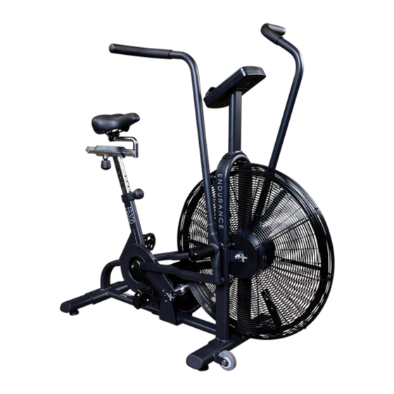
- Page 1 FB300B Endurance ® FB300B Fan Bike User Manual V. FB300B-02282019...
-
Page 2: Table Of Contents
Table of Contents Table of Contents...................... Introduction........................ Important Safety Information................Before You Begin....................... Assembly........................6 - 13 Setting up FB300B....................Dimension............................Console Overview..................... 16 - 18 Console Operation....................19 - 22 23 - 24 Monitoring Your Heart Rate................. Chest Strap Operation..................... General Maintenace.................... -
Page 3: Introduction
Introduction Congratulations!! Thank you for purchasing your new Endurance ® Fan Bike. Using state-of-the-art techniques, robust frame structure and superior ergonomic design, Endurance ® Fan Bike set a new standard for excellence. The Endurance ® Fan Bike can improve your quality of life by keeping you fit and healthy, increasing your energy levels and enhancing your lifestyle. -
Page 4: Important Safety Information
Important Safety Information Save this Owner’s Manual! Before beginning any fitness program, you should obtain a complete physical examination from your physician. When using exercise equipment, you must always take basic precautions, including the following: Read all instructions before using your Endurance ® Fan Bike. These instructions are written to ensure your safety and to protect the unit. -
Page 5: Before You Begin
Before You Begin The Endurance ® FB300B is carefully tested and inspected before shipment. We have shipped the unit in several pieces that require assembly. Carefully unpack the unit in a clear area and lay the pieces on the floor near the area where you plan to use the equipment. - Page 6 Step 1 NOTE: Some hardware components may be pre-assembled. Be aware of Nylon lock nuts not fully screw onto bolts, they must be tightened with a wrench to ensure proper engagement. 1A. Attach Front Stabilizer (M) to Main Frame (A) using: Two M8x20mm Button Head Cap Screws (#5) Two M8 Lock Washers (#6) Two M8 Washers (#7)
- Page 7 Step 1 步骤一: 1:用内六角盘头螺钉(5)、 弹垫(6)、平垫(7)分别将前底管(M)、后底管(N)锁紧在主 架(A)上. 步骤一: 1:用内六角盘头螺钉(5)、 弹垫(6)、平垫(7)分别将前底管(M)、后底管(N)锁紧在主 架(A)上. Above shows STEP 1 assembled and completed.
- Page 8 Step 2 NOTE: Some hardware components may be pre-assembled. Be aware of Nylon lock nuts not fully screw onto bolts, they must be tightened with a wrench to ensure proper engagement. 2A. Attach the Handle Bars (E & F) & M16 Lock Washers (#63) into the Main Frame (A) by threading Handle Bar Pivot Shafts (#21).
- Page 9 步骤二: Step 2 步骤二: 1:先用脚踏杆轴(21)将左摆杆(E)、右摆杆(F)含在主架(A)上的两侧,(先不要锁紧); 1:先用脚踏杆轴(21)、弹垫(63)将左摆杆(E)、右摆杆(F)含在主架(A)上的两侧,(先不要锁紧 2:用轴肩螺栓(14)、六角薄螺母(15)、尼龙螺母(17)将左摆杆(E)、右摆杆(F)与连杆(H)连接锁 ); 紧,并将脚踏杆轴(21)锁紧。 2:用轴肩螺栓(14)、六角薄螺母(15)、尼龙螺母(17)将左摆杆(E)、右摆杆(F)与连杆(H)连接锁 3:用内六角圆柱头螺钉(27)、平垫(28)将鞍座(3)锁紧在鞍座横管(D)上. 紧,并将脚踏杆轴(21)锁紧。 3:用内六角圆柱头螺钉(27)、平垫(28)将鞍座(3)锁紧在鞍座横管(D)上. Above shows STEP 2 assembled and completed.
- Page 10 Step 3 NOTE: Some hardware components may be pre-assembled. Be aware of Nylon lock nuts not fully screw onto bolts, they must be tightened with a wrench to ensure proper engagement. 3A. Screw (counterclockwise) Left Pedal (P) onto Left Crank (#1). 3B.
- Page 11 步骤三: 步骤三: 将左脚蹬(P)、右脚蹬(Q)分别锁紧在左曲柄 (1)、右曲柄(2)上;注:左脚蹬 (P)应逆时针锁 Step 3 将左脚蹬(P)、右脚蹬(Q)分别锁紧在左曲柄 (1)、右曲柄(2)上;注:左脚蹬 (P)应逆时针锁 紧 右脚蹬(Q)应顺时针锁紧。 按如下图箭头所指的方向,在运动过程中时刻保持 左脚蹬(P)、右 紧 右脚蹬(Q)应顺时针锁紧。 按如下图箭头所指的方向,在运动过程中时刻保持 左脚蹬(P)、右 脚蹬(Q) 在旋紧状态,否则将会使 左脚蹬(P)、右脚蹬(Q) 的牙损坏。 脚蹬(Q) 在旋紧状态,否则将会使 左脚蹬(P)、右脚蹬(Q) 的牙损坏。 Above shows STEP 3 assembled and completed.
- Page 12 Step 4 NOTE: Some hardware components may be pre-assembled. Be aware of Nylon lock nuts not fully screw onto bolts, they must be tightened with a wrench to ensure proper engagement. 4A. Feed the Speed Sensor Cable (#30) through the Upright (B). 4E.
- Page 13 步骤四: 步骤四: 1:先将感应线 (30)从把立管 (B)下端穿入上端穿出,然后用内六角盘头螺钉(5)、弹垫(6)、平垫 Step 4 1:先将感应线 (30)从把立管 (B)下端穿入上端穿出,然后用内六角盘头螺钉(5)、弹垫(6)、平垫 (7)将把立管(B)锁紧在主架(A); (7)将把立管(B)锁紧在主架(A); 2:先将感应线(30)与电子表 (S)相应接头连接好 ,然后用十字盘头螺钉 (29)将电子表(S)锁紧在把立管 (B) 2:先将感应线(30)与电子表 (S)相应接头连接好 ,然后用十字盘头螺钉 (29)将电子表(S)锁紧在把立管 (B) 的表托板上。 的表托板上。 Above shows STEP 4 assembled and completed.
-
Page 14: Setting Up Fb300B
SETTING UP FB300B PLACEMENT IN YOUR HOME To make exercise a desirable daily activity for you, the FB300B should be placed in a com- fortable and attractive setting. This Bike is designed to use minimal floor space and to fit nicely in your gym/home. -
Page 15: Dimension
Dimensions... -
Page 16: Console Overview
Console Overview Take a few moments to review the console layout. - Page 17 Console Overview CONSOLE SCREEN DISPLAY Interval Display The top part will signal which interval program (10/20, 20/10 or Custom) is currently running. The graphic will show whether the workout is at Work or Rest Period. The Total Time will count up the total workout time. The Large Numericl display will count the current Work or Rest time.
- Page 18 Console Overview Heart Rate When the user’s heart rate signal is detected via the wireless chest strap, the user’s current heart rate will be displayed on the bottome left side of the screen. When the Target Heart Rate program is selected, 65% and 85% will display altenatively.
-
Page 19: Console Operation
Console Operation INITIAL SETUP Metric & Standard Unit: The initial factory setting is in “Miles”. To toggle between Miles and Kilometers, press and hold “START” & “ENTER” buttons for 2 seconds. Press “UP” or “DOWN” arrows to select KM or ML and then press “ENTER” to confirm. Battery Installation: Console operates on two AA batteries. - Page 20 Console Operation QUICK PROGRAMS There are eight Quick Programs (QUICK START, 10/20 INTERVAL, 20/10 INTERVAL, CUSTOM INTERVAL, TARGET TIME, TARGET DISTANCE, TARGET CALORIES, TARGET HEART RATE) to choose from. The workout summary will be display at the end of workout or press the “STOP” button. QUICK START This program allows the user to start the workout immediately as soon as the user starts to pedal without pressing any button.
- Page 21 Console Operation 3. Press the “UP” or “DOWN” buttons to adjust the work interval time and then press the “ENTER” button to confirm the value. 4. Press the “UP” or “DOWN” buttons to adjust the rest interval time and then press the “ENTER”...
- Page 22 Console Operation TARGET HEART RATE This program allows the use to set the target heart rate for the workout. A wireless heart rate strap must be worn in order to detect the user’s heart rate. The program will actomatically calculate the maximum, 65% & 85% of the heart rate based on the user’s age.
-
Page 23: Monitoring Your Heart Rate
Monitoring Your Heart Rate To obtain the greatest cardiovascular benefits from your exercise workout, it is im- portant to work within your target heart rate zone. The American Heart Association (AHA) defines this target as 50% -85% percent of the Maximum Heart Rate. The Maximum Heart Rate may be roughly calculated by subtracting the user’s age from 220. - Page 24 Monitoring Your Heart Rate FITNESS SAFETY The Heart Rate chart indicates average rate zones for different ages. A variety of dif- ferent factors (including medication, emotional state, temperature and other con- ditions) can affect the target heart rate zone that is best for you. Your physician or health care professional can help you determine the exercise intensity that is appro- priate for your age and condition.
-
Page 25: Chest Strap Operation
Chest Strap Operation Your Endurance ® Fan Bike has the capability to determine Heart Rate with the use of a Heart Rate Chest Strap. A Heart Rate Chest Strap can be purchased seperately. In all Heart Rate Control programs, the console only accepts the heart rate signal from the chest strap transmitter while the pulse grip heart rate function is disabled. -
Page 26: General Maintenace
General Maintenace Your Endurance® FB300B Exercise Fan Bike has been manufactured to withstand many hours of use with minimal maintenance. Here are some maintenance tips to keep your Endurance® FB300B Exercise Fan Bike at its best. CLEANING Periodically wipe down your machine with mild, soapy water or a diluted general purpose non-abrasive household cleaner. -
Page 27: Troubleshooting Guide
Trouble Shooting Guide Symptom Solution Possible Cause Console cable is not connected? Verify that the console cable is connected properly. Console has no power. Call the Endurance ® service number. The console is faulty? Check that the sensor magnet is correctly fitted and passes in front of the sensor. -
Page 28: Stretching & Flexibility
Stretching & Flexibility Flexibility is an important component of physical fitness and needs to be addressed in a resistance training program. The two main purposes for stretching are injury preven- tion and a faster rate of recovery from exercise. Stretching should be performed in both the warm up and cool down phases of a training session. -
Page 29: Warm-Up/Cool Down Exercises
Warm Up/Cool Down Exercises UPPER BACK Cross Arm in Front of Chest MUSCLE(S) AFFECTED: latissimus dorsi and teres major 1. Stand or sit with the right arm slightly flexed (15° to 30°) and adducted across the chest. 2. Grasp the upper arm just above the elbow, placing the left hand on the posterior side of the upper arm. - Page 30 Warm Up/Cool Down Exercises LOWER BACK Semi-Leg Straddle MUSCLE(S) AFFECTED: spinal erectors 1. Sitting, knees flexed 30 to 50 degrees, let the legs totally relax. 2. Point the knees outward; the lateral side of the knees may or may not touch the floor. 3.
- Page 31 Warm Up/Cool Down Exercises CHEST/SHOULDER Straight Arms Behind Back MUSCLE(S) AFFECTED: deltoids and pectoralis major 1. Standing, place both arms behind back. 2. Interlock fingers with palms facing each other. 3. Straighten arms fully. 4. Slowly raise the straight arms; hold for 10 to 15 seconds. 5.
- Page 32 Warm Up/Cool Down Exercises ANTERIOR OF THIGH AND HIP FLEXOR Side Quadricep Stretch MUSCLE(S) AFFECTED: quadriceps and iliopsoas 1. Lie on left side with both legs straight. 2. Place left forearm flat on floor and upper arm perpendicular to floor. 3.
- Page 33 Warm Up/Cool Down Exercises POSTERIOR OF THIGH Stretching the hamstrings Semistraddle (Figure Four) with emphasis on insertion of the hamstrings and calves MUSCLE(S) AFFECTED: gastrocnemius, hamstrings and spinal erectors 1. Sit with the upper body nearly vertical and legs straight. 2.
- Page 34 Warm Up/Cool Down Exercises GROIN Butterfly MUSCLE(S) AFFECTED: adductors and sartorius 1. Sitting with the upper body nearly vertical and legs straight, flex both knees as the soles of the feet come together. 2. Pull feet toward body. 3. Place hands on feet and elbows on legs. 4.
- Page 35 Warm Up/Cool Down Exercises HIPS Forward Lunge (Fencer) MUSCLE(S) AFFECTED: iliopsoas, rectus femoris 1. 1. Standing, take a long step forward (as with the lunge) with the right leg and flex the right knee until it is directly over the right foot. 2.
-
Page 36: Parts & Hardware List
Parts & Hardware List Part# Description MAIN FRAME UPRIGHT VERTICAL SEATPOST HORIZONTAL SEATPOST LEFT HANDLE BAR RIGHT HANDLE BAR FOOT PEG LINKAGE LEFT CHAIN COVER RIGHT CHAIN COVER FRONT STABILIZER REAR STABILIZER LEFT PEDAL RIGHT PEDAL CONSOLE LEFT STEP CRANK RIGHT STEP CRANK LEFT CRANK RIGHT CRANK... - Page 37 Parts & Hardware List Part# Description M10 FLAT WASHER M10 NYLON LOCK NUT ø35xø17x10mm BEARING M8x45mm SHOULDER BOLT M8 HEX NUT ø22xø8X9mm BEARING M8 NYLON LOCK NUT M14 FLANGE NUT ø22xø17x1mm WASHER ø35xø17x10mm BEARING HANDLE BAR PIVOT SHAFT HANDLE GRIP POP PIN BUSHING END CAP...
- Page 38 Parts & Hardware List Part# Description M10 FLANGE NUT TENSION BOLT U BRACKET M6 HEX NUT M10 HEX NUT ø16xø10x6mm SPACER ø26xø10x8mm BEARING M5x25mm BUTTON HEAD CAP SCREW CHAIN WHEEL HUB ASSEMBLY M5 NYLON LOCK NUT SPROCKETS LOCK NUT ø10x146mm SHAFT M10 ACORN NUT LEFT SHROUD RIGHT SHROUD...
- Page 39 Parts & Hardware List Part# Description AXLE LOCK WASHER M16 FLANGE NUT M10...
-
Page 40: Exploded Drawing
Exploded Drawing... - Page 41 Exploded Drawing...
- Page 42 Serial number is Located on the Frame FB300B Model name Purchase Date : _______________________________ Serial number : _______________________________ Customer Tech Support Hotline Toll Free: 1-800-556-3113 Phone: 1-708-427-3555 Fax: 1-708-427-3556 Hours: M-F 8:30-5:00 CST E-Mail: service@bodysolid.com...
Need help?
Do you have a question about the ENDURANCE FB300B and is the answer not in the manual?
Questions and answers