Table of Contents
Advertisement
Quick Links
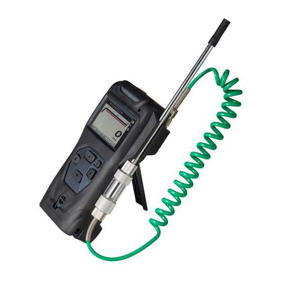
Portable Gas Detector
XP-3000II Series
Instruction Manual
This instruction manual is for the nine models listed below.
Keep this manual for easy reference.
Carefully read this manual prior to use.
XP-3310II
XP-3340II
1-gas
XP-3360II
XP-3360II-W
XP-3318II
2-gas
XP-3368II
XP-3368II-W
XP-3380II
O
2
XP-3380II-E
Model Variations
Model
Combustible gas (LEL detection)
Combustible gas (vol% detection)
Combustible gas (ppm detection)
Combustible gas (LEL & ppm detections)
Combustible gas (LEL detection)+O
Combustible gas (ppm detection)+O
Combustible gas (LEL & ppm detections)+O
Oxygen
Oxygen in combustion exhaust
Target Gas
2
2
2
Advertisement
Table of Contents

Related Manuals for New Cosmos Electric XP-3000II Series


Summary of Contents for New Cosmos Electric XP-3000II Series
- Page 1 Portable Gas Detector XP-3000II Series Instruction Manual This instruction manual is for the nine models listed below. Keep this manual for easy reference. Carefully read this manual prior to use. Model Variations Model Target Gas XP-3310II Combustible gas (LEL detection)
-
Page 2: Table Of Contents
Table of Contents Package Contents ....................1 Optional Items (sold separately) ................2 Introduction ......................3 Symbols Used in this Manual ................3 Explosion-proof Requirements ................4 Safety Precautions ....................6 Precautions for Battery Handling ................8 Precautions for Wireless Communication.............. 8 Unit and Components ................... - Page 3 3-3-7. LCD backlight and flashlight on/off ............23 3-3-8. Return to HOME screen ................23 3-3-9. Change unit of measurement (only for XP-3360II-W and XP-3368II-W) ... 23 3-3-10. Data logging (for the unit with Bluetooth function installed) ....23 3-3-11. Mute audio gas alarm ................23 3-4.
- Page 4 Appendix: Utility for Gas Detector App ................i A1. Utility for Gas Detector ..................i A2. Compatible iOS/Android Devices ..............i A3. Language Settings .................... i A4. App Installation and Uninstallation ..............i A4-1. Installation ..................... i A4-2. Uninstallation ....................ii A5.
-
Page 5: Package Contents
Package Contents A standard package consists of the following items. If any items are missing or damaged, please contact New Cosmos or its authorized representative for replacement. Item Quantity Portable gas detector (with elastomer case) Shoulder strap 1m sampling tube (SH-301K-1A) Curl cord type with drain filter and probe nozzle included 1m sampling tube for solvent gas detection (SH-401-1A) (Either type) -
Page 6: Optional Items (Sold Separately)
Optional Items (sold separately) Item (model) Description Leather case (C-37) Protects from dirt and scratches Screen protective film (SPF- Protects the LCD from dirt and scratches (x 3 pcs) Alligator clip (ST-22) Use with screws. Use to wear the detector by hanging it on a belt etc. -
Page 7: Introduction
1. Introduction Thank you for purchasing the New Cosmos XP-3000II series portable gas detector. Prior to use, please read this instruction manual carefully to ensure safe and reliable operation. XP-3000II series has single-gas (1-gas) and two-gas (2-gas) models available. 1-gas models measure one combustible gas or oxygen, while 2-gas models simultaneously measure one combustible gas and oxygen. -
Page 8: Explosion-Proof Requirements
Introduction Explosion-proof Requirements Follow the conditions below to comply with the explosion-proof requirements. Models which use non-rechargeable alkaline AA batteries: ATEX: II 1G Ex ia da IIC T4 Ga (Other than XP-3380II) II 1G Ex ia IIC T4 Ga (XP-3380II) IECEx: Ex ia da IIC T4 Ga (Other than XP-3380II) Ex ia IIC T4 Ga... - Page 9 Introduction Batteries to use: Alkaline batteries: Toshiba alkaline AA battery LR6 x 4pcs, Panasonic alkaline AA battery LR6X x 4pcs, Duracell alkaline AA battery MN1500 x 4pcs, Energizer alkaline AA battery E91 x 4pcs, or Varta alkaline AA battery 4106 x 4pcs Rechargeable batteries: New Cosmos nickel metal hydride AA battery HR-3UTG x 4pcs Silver oxide battery (for the clock):...
-
Page 10: Safety Precautions
Introduction Safety Precautions To ensure safe operation, follow the precautions below. Only use this product in accordance with the applicable laws and regulations. When a gas alarm is activated, immediately take all the necessary DANGER measures to prevent accidents including gas explosion and oxygen deficiency. - Page 11 Introduction If this product is to be unused for an extended period of time, remove the CAUTION batteries from the unit. Failure to do so may cause them to leak or discharge, leading to product failure. Even when this product is to be unused for an extended period of time, turn on the product once every 6 months and check that the pump normally works (by running the pump for approx.
-
Page 12: Precautions For Battery Handling
Introduction Precautions for Battery Handling This product uses four batteries. Follow the precautions below for safe use of batteries. Dispose of used batteries in accordance with the applicable laws and WARNING regulations. Improper use of batteries may lead to battery lakage, excessive heat, ignition or explosion. -
Page 13: Unit And Components
2. Unit and Components Gas Detector ⑫ ⑪ ⑦ ⑧ ⑩ ㉓ ⑲ ⑮ ⑯ ㉑ ⑳ ⑨ ② ⑭ ① ④ ⑤ ③ ⑰ ⑬ ⑥ ⑱ With elastomer Without elastomer case attached case attached ㉒ Item Component Function Used to turn the detector on/off or move to the gas concentrations screen (HOME) Power button... -
Page 14: Lcd
Unit and Components Item Component Function ⑬ Battery cover Cover for battery compartment Battery cover lock Unlock/lock the battery cover ⑭ Sampling tube holder Holds a gas sampling tube ⑮ Screw hole (2 places) Used to attach an alligator clip (sold separately) with two screws ⑯... -
Page 15: Gas Sampling Tube (Curl Cord Type)
Unit and Components 1m Gas Sampling Tube (curl cord type) ④ ③ ② ① Item Component Function Gas sampling tube (1m) Conveys gas to the gas detector ① Coupler Connects to the gas detector ② Prevents water and dust from entering the gas detector, Drain filter ③... -
Page 16: Shoulder Strap
Unit and Components Shoulder Strap ① ② Item Component Function Used to carry a gas detector by looping the shoulder strap Shoulder strap over neck or shoulder ① Consists of two sub-straps connected by a carabiner Connects a shoulder strap to the gas detector Loop (2 places) ②... -
Page 17: Operation
3. Operation 3-1. Preparation 3-1-1. Battery installation Units are shipped without batteries. Remove the battery cover and then install the four supplied batteries. See “Battery Replacement” on pages 38 to 39 for the procedure. The battery cover is pre-installed when shipped. 3-1-2. -
Page 18: Operating Procedure
Operation 3-2. Operating Procedure Perform routine check prior to use (page 44). WARNING If the detector is marked with both temperature classes T3 and T4, before deploying the detector in a hazardous area, the user shall check the battery type via the LCD, and ensure that, if MiMh batteries are fitted, the detector is only used in areas requiring temperature class T3. - Page 19 Operation Press and hold the power button until the power-on screen (company logo ) is displayed on the LCD. --> After the unit beeps once, the “model, serial No. and battery type”, “target gases”, “full scale values”, “alarm set values”, “previous calibration date” and “log memory usage”, and“Bluetooth not available”screens will be displayed in sequence.
-
Page 20: Detection
Operation 2. Detection When the HOME screen is displayed, it means that the detector is ready for use. --> See “LCD” on page 10. --> See “HOME Screen” on page 17. --> See “Gas Alarm Operation” on page 18. HOME When the ○... -
Page 21: Power Off
Operation 3. Power off Press and hold the power button for four seconds. “POWER OFF” will be displayed. Then, a countdown will begin with “3,” “2,” and “1” being displayed in sequence along with a beep for each; in the end, three beeps will be heard. The LCD will turn off and then the unit will turn off. -
Page 22: Gas Alarm Operation
Operation Gas alarm operation When the gas concentration exceeds the gas alarm set value, the unit will start beeping, alarm light will start blinking red, “AL” or “ALARM” will appear on the LCD, and the backlight will turn on. When the gas concentration falls below the gas alarm set value, the gas alarm will automatically deactivate (auto-resetting). -
Page 23: Functions In Normal Operation
Operation 3-3. Functions in Normal Operation This section describes functions available during normal operation through button operation. “Normal operation” is a status in which the detector is capable of gas monitoring/detection after powering-up, and normally the gas concentrations screen (HOME) is displayed on the LCD. During normal operation, the unit keeps monitoring the gas... -
Page 24: Trend Graph Display
Operation 3-3-2. Trend graph display (1) During normal operation, use the ��/▼ button to display the gas concentration trend for the last one to five minutes’ span in a graph form. Gas concentration Target gas GAS1 alarm Select the time span by referring to “Trend NOTE graph span setting”... -
Page 25: Stopwatch
Operation (6) To reset the countdown, press the ��/▼ button to display “CLEAR”, and then press the ▶ button for confirmation. If the LCD returns to the HOME screen while NOTE the timer is active, the timer icon and the countdown will be displayed on the right and bottom respectively. -
Page 26: Zero Adjustment (Zeroing)
Operation 3-3-5. Zero adjustment (zeroing) Perform zero adjustment in clean air. Inaccurate gas WARNING concentrations will be indicated if zero adjustment is done in a gas atmosphere. During normal operation, press and hold the ◀ button for four seconds to start zero adjustment. -
Page 27: Lcd Backlight And Flashlight On/Off
Operation 3-3-7. LCD backlight and flashlight on/off (1) Press and hold the �� button. The LCD backlight will turn on with a long beep. (2) Press and hold the �� button again. The flashlight will turn on with a long beep. (3) Press and hold the ��... -
Page 28: Settings
Settings 3-4. Settings From the Setup Menu screen, it is possible to change the target gas; convert to other gas’s concentration; turn on/off Bluetooth; set the time span for trend graph display; set logging interval rate; turn on/off logging; delete logs; adjust the audio volume; set the alarm set value;... -
Page 29: Go To Setup Menu
Settings 3-4-1. Go to setup menu Press the ▶ button while on the HOME screen. “Set Up” is highlighted in blue (selected). Then press the ▶ button to confirm the selection. The “Setup Menu” screen will be displayed. “Set Up” highlighted in blue Setup Menu When the conversion mode is active, pressing the ▶... -
Page 30: (A) Change Target Gas
Settings (A) Change target gas The target gas can be changed (selected) if the unit is a model NOTE capable of detecting more than one combustible gas. The set details in this mode will be saved even after the unit is turned off or the batteries are removed. -
Page 31: (C) Bluetooth On/Off
Settings While on the Setup Menu screen, use the ��/▼ button to select “Conversion”. Then press the ▶ button to confirm the selection. Once this step has been completed, a list of convertible gas options will be displayed. Use the ��/▼ button to select the desired gas type from the list. -
Page 32: (D) Trend Graph Span Setting
Settings (D) Trend graph span setting While on the Setup Menu screen, use the ��/▼ button to select “Graph Scale”. Then press the ▶ button to confirm the selection. Set the span to the desired value with the ��/▼button. Then press the ▶ button to confirm the setting. The settable value is 1, 2, 3, 4, or 5 minutes. - Page 33 Settings Select the unit of measurement for the logging interval rate with the ��/▼ button. Then press the ▶ button to confirm the selection. The settable unit is “00ms”, “sec”, “0sec”, “min”, “0min” or “hour”. (E-2) Logging on/off To start (or end) data logging, select “On/Off” on the Log Setup screen.
- Page 34 Settings The factory default of the logging interval rate is one second. NOTE The minimum settable interval rate is 200 ms. The logging period is approx. 40 hours when the logging interval rate is set to 10 seconds for 2-gas models. It is approx. 70 hours for 1-gas models.
-
Page 35: (F) Audio Volume Control
Settings (F) Audio volume control The factory default for audio volume level is medium. WARNING The change of audio level should be performed by the safety supervisor. When the level is changed, perform an alarm test (page 33) to check the audio level. ... -
Page 36: (G) Alarm Set Value Setting And Alarm Test
Settings (G) Alarm set value setting and alarm test (G-1) Alarm set value Setting of the alarm set value is very important. The alarm set WARNING value should be changed by the safety supervisor. While on the Setup Menu screen, use the ��/▼ button to select “Alarm”. -
Page 37: (H) Clock Adjustment
Settings (G-2) Alarm test To perform an alarm test, select “Alarm Test” on the “Alarm Setup” screen with the ��/▼ button, and then press the ▶ button. “ALARM” will be displayed. Press the ▶ button to start the test. The unit will start beeping with red-blinking alarm light (a gas alarm is simulated). -
Page 38: Span Adjustment
Settings 3-5. Span Adjustment Span adjustment is enabled only with XP-3310II, XP-3318II, XP-3360II-W, and XP- 3368II-W units, in which GAS1 (target gas) is set to methane, isobutane, hydrogen, or propane. Perform a zero adjustment (page 22) before a span adjustment. Go to the span adjustment mode and then perform a span adjustment (1) Press the ▶... -
Page 39: Bump Test
Settings 3-6. Bump Test Bump test is to check that the reading falls within the normal range by using the actual test gas and optional EG-129 bump tester. Go to the bump test mode and then perform a bump test (1) Press the ▶... -
Page 40: Error Messages
4. Error Messages If an error occurs in the detector, the corresponding error message will be displayed on the LCD, the unit will beep, and the alarm light will blink yellow. (The unit will give two beeps instead of beeping constantly, if a device error occurs when the audio level is set to MUTE.) The table below lists the major error messages. - Page 41 Error Messages Error message Error condition Possible cause Action on screen Detector error Detector may be Remove the batteries, broken reinstall them, and turn on the unit. If the unit does not reset to normal, contact us for repair. Alarm may activate Turn off the unit, and then while log data is turn it on again.
-
Page 42: Consumable Replacement
5. Consumable Replacement Battery Replacement Do not replace the batteries in a hazardous area. WARNING Only use specified batteries below. Using batteries other than those specified may impair the product’s explosion-proof performance. - Non-rechargeable batteries: Toshiba alkaline AA battery LR6, Panasonic alkaline AA battery LR6X, Duracell alkaline AA battery MN1500, Energizer alkaline AA battery E91, or Varta alkaline AA battery 4106... -
Page 43: Charge Batteries
Consumable Replacement (4) Install the battery cover. Rotate the battery cover lock (screw) clockwise until it is tight (until the head of the screw is flush with the battery cover surface) with a Phillips screwdriver. Firmly tighten the battery cover lock. Loose battery cover CAUTION lock may impair the product’s explosionproof/waterproof performance. -
Page 44: Filter Element Replacement
Consumable Replacement The user can estimate the timing of battery recharging by checking the battery level indicator on the LCD. When the battery is drained, “Battery Empty” will be displayed on the LCD, the unit will beep, and the detector will not detect gases any longer. The LCD will then turn off when the batteries are completely drained. - Page 45 Consumable Replacement Replace the filter element for the cooling drain filter (only for XP-3380II-E) (1) Pull and separate the drain cup from the cooling drain filter. (2) Remove the gasket (O-ring) from the drain cup by using a small screwdriver etc. (3) Replace the filter element (FE-10) with a new one.
-
Page 46: Sensor Replacement (Oxygen Sensor)
Do not replace the sensor in a hazardous area. Only use specified sensors. Only use a New Cosmos Electric Co., Ltd manufactured sensor, and ensure that the sensor has correct part number. ... - Page 47 Consumable Replacement (3) Remove the sensor spacer. Pinch the head of the oxygen sensor and slowly lift and remove it from the detector. (There is no need to remove the combustible gas sensor.) Oxygen sensor Sensor spacer with 2 gaskets Combustible gas sensor ...
-
Page 48: Maintenance
6. Maintenance This product is a precision instrument. Please perform the periodical checks and inspections below to maintain the detector’s performance and ensure safety. In the event of a failure to follow the safety precautions (pages 6 to 8), such as impact shock from dropping or water ingress inside the detector, or use in conditions outside the specifications (pages 48-52), such as usage in temperature/humidity exceeding the specified range, please contact New Cosmos or your New Cosmos representative for inspection (fees may apply). -
Page 49: Annual Inspection
Maintenance Annual Inspection Contact New Cosmos or your New Cosmos representative to perform a periodic inspection including sensor calibration and filter replacement at least once a year to maintain the product accuracy. The recommended replacement cycle for combustible sensors is WARNING three years. -
Page 50: Troubleshooting
7. Troubleshooting Before contacting us for service repair, perform basic troubleshooting using the table below. If the detector locks up (cannot be turned off), remove all batteries. After a few minutes, put the batteries back in and turn on the detector. Symptom Cause Action... -
Page 51: Warranty
8. Warranty The warranty period is one (1) year from the date of purchase. You are entitled to the limited warranty, if the product malfunctions due to a manufacturing defect during normal use in accordance with the instruction manual, specifications and labels. -
Page 52: Specifications
9. Specifications Product Specifications ■ XP-3310II, XP-3318II, XP-3340II, XP-3360II-W, XP-3368II-W, XP- Model 3360II, XP-3368II, XP-3380II, XP-3380II-E Target gas As per Table 9-1 Detection principle As per Table 9-1 Sensor operation method Continuous Gas sampling method Extractive Measuring range As per Table 9-1 (Service range Accuracy As per Table 9-1... - Page 53 Specifications Sensor symbol for CS, CT and CH sensors Compliance ATEX: II 1G Ex da IIC Ga IECEx: Ex da IIC Ga Ingress protection Equivalent to IP67 Wireless Bluetooth 5.0 Self-diagnosis (sensor error), zero adjustment, battery level indication, flashlight, peak hold, LCD backlight, audio gas alarm Main features muting during gas alarm, time indication, alarm test, alarm volume change, audio muting, data logging...
- Page 54 Specifications Table 9-1 Model XP-3310II XP-3318II Combustible gas/ Combustible gas/ Target gas Oxygen solvent gas solvent gas Detection principle Catalytic Catalytic Galvanic cell Measuring range 0–100%LEL 0–100%LEL 0–25vol% (Service range) (100.1–110.0%LEL) (100.1–110.0%LEL) (25.1–50.0vol%) Accuracy ±5%F.S. ±5%F.S. ±0.3vol% Resolution 0.1%LEL 0.1%LEL 0.1Vol% Gas alarm set value 20%LEL...
- Page 55 Specifications Table 9-1 (continued) Model XP-3360II XP-3368II Combustible gas/ Combustible gas/ Target gas Oxygen solvent gas solvent gas Detection principle Catalytic Catalytic Galvanic cell 0–5000 ppm 0–5000 ppm Measuring range (5001–5500 ppm) (5001–5500 ppm) 0–25vol% (Service range) (25.1–50.0vol%) 0–10000 ppm 0–10000 ppm (10001–11000 ppm) (10001–11000 ppm)
-
Page 56: Explosion-Proof Specifications
Specifications Explosion-proof Specifications ■ Model XP-33xxII Models which use non-rechargeable alkaline AA batteries: ATEX: II 1G Ex ia da IIC T4 Ga (Other than XP-3380II) II 1G Ex ia IIC T4 Ga (XP-3380II) IECEx: Ex ia da IIC T4 Ga (Other than XP-3380II) Ex ia IIC T4 Ga (XP-3380II) -
Page 57: External Markings For Explosion-Proof Models
Specifications External Markings for Explosion-proof Models ■ 1. Manufacturing label 4. CE marking label Models: XP-3310II XP-3318II QAN notified body XP-3340II ATEX certificate No. XP-3360II XP-3360II-W XP-3368II XP-3368II-W IECEx certificate No. XP-3380II XP-3380II-E 2. Explosion-proof label 5. Warning label for battery handling (ATEX, IECEx) 6. -
Page 58: Disposal
10. Disposal Dispose of a used gas detector, sensor or battery as industrial waste in accordance with the applicable local laws and regulations. Battery disposal Used batteries must be disposed of in accordance with the applicable laws and regulations. The Waste Electrical and Electronic Equipment (WEEE) directive (2012/19/EU) is intended to promote recycling of electrical and electronic equipment and their components at end of life. -
Page 59: Detection Principle
11. Detection Principle Catalytic sensor (combustible gas) Catalytic combustion occurs on the catalytic layer applied on a platinum coil even if the gas concentration is well below the lower flammable limit (LFL). This causes a rise in temperature of the platinum coil and increases its electrical resistance. -
Page 60: Glossary
12. Glossary Term Definition Target gas Specific gas to be detected and used to trigger alarms. Detection range A range of target gas concentrations that can be displayed and or measuring trigger alarms. range Service range A range of target gas concentrations the detector is able to indicate, which are usually outside the Detection Range and used only as reference. -
Page 61: Appendix: Utility For Gas Detector App
Appendix: Utility for Gas Detector App A1. Utility for Gas Detector The Utility for Gas Detector app is a utility application that connects your iOS or Android device (e.g., Android phone, iPhone, iPad) to a gas detector via Bluetooth. This allows your iOS or Android device to display the real-time gas concentrations, temperature and humidity levels detected by the gas detector and send you an email alert in case of a gas alarm or detector error (e.g., pump error, sensor error, and empty battery). -
Page 62: A4-2. Uninstallation
Appendix: Utility for Gas Detector App ■ Android (1) Open Google Play. (2) Tap Apps in the bottom navigation bar. (3) Tap the search box. (4) Enter “utility for gas detector” in the box, then tap Search to start the search. (5) “Utility for gas detector”... -
Page 63: A5. Pairing With A Gas Detector
Appendix: Utility for Gas Detector App A5. Pairing with a Gas Detector Run the Utility for Gas Detector app and connect it to a gas detector by following the steps below. (1) Turn on the gas detector, then turn its Bluetooth on. (3-4. “Settings” on page 27) (2) Turn on your smartphone’s Bluetooth. -
Page 64: A6. Select Device Screen
Appendix: Utility for Gas Detector App A6. Select Device Screen The buttons and indications on the Select device screen are described below. This screen enables you to select a gas detector to pair with via Bluetooth. ② ① ③ ④ ⑤... -
Page 65: Serial Number Entry
Appendix: Utility for Gas Detector App Serial Number Entry ■ ① Item Button/indication Function Enter the last 5 digits of the serial number of the gas detector. Tap OK to confirm. Serial number entry For example, when the serial number is “XP-3318II 00600122”, enter “00122.”... -
Page 66: A7. Gas Concentration Screen
Appendix: Utility for Gas Detector App A7. Gas Concentration Screen The buttons and indications on the Gas concentration screen are described below. This screen displays the real-time gas concentrations sent by the gas detector. Using this screen, you can change the gas types to be displayed and show/hide the temperature and humidity. -
Page 67: A8. Temperature And Humidity Screen
Appendix: Utility for Gas Detector App A8. Temperature and Humidity Screen The buttons and indications on the Temperature and Humidity screen are described below. This screen shows the real-time temperature and humidity sent from the gas detector. ① ② ③ ④... -
Page 68: A9. Display Log Data Screen
Appendix: Utility for Gas Detector App A9. Display Log Data Screen The buttons and indications on the Display log data screen are described below. Using this screen, you can view the old log data recorded in the gas detector. List of Log Data ■... -
Page 69: Viewing The Contents Of The Log Data
Appendix: Utility for Gas Detector App Viewing the Contents of the Log Data ■ ② ③ ⑥ ① ④ ⑤ Item Button/indication Function Appears while the app is accessing and acquiring the log “Wait a moment…” data from the gas detector; if the data size is bigger, it will message take longer. -
Page 70: A10. Settings Screen
Appendix: Utility for Gas Detector App A10. Settings Screen The buttons and indications on the Settings screen are described below. This screen is used to operate various settings such as those for a connected gas detector, email, and user information. ①... -
Page 71: A10-1. Memory Usage & Refresh Screen
Appendix: Utility for Gas Detector App Item Button/indication Function Home button Tap to go to the Select device screen. Gas concentration Tap to go to the Gas concentration screen. button Temperature and Tap to go to the Temperature and Humidity screen. humidity button Tap to go to the Display log data screen. -
Page 72: A10-2. Ble Communication Interval Screen
Appendix: Utility for Gas Detector App A10-2. BLE Communication Interval Screen ① ② ④ ⑤ ③ Item Button/indication Function Tap to return to the Settings screen. Back button (Tap the ◁ button instead on Android phones) Text in brackets indicates an applicable time unit. BLE communication E.g.,: interval... -
Page 73: A10-3. Ble Communication Interval Edit Page
Appendix: Utility for Gas Detector App A10-3. BLE Communication Interval Edit Page ① ② ③ Item Button/indication Function Enter the integer part of your desired BLE Sampling time communication interval value here. Time unit Select your desired time unit from the list. Tap OK to confirm the editing, or tap Cancel to delete the editing. -
Page 74: A10-4. Turning On The Send Email Function
Appendix: Utility for Gas Detector App A10-4. Turning on the Send Email Function This app sends you an email alert about a gas an event detected by the gas detector (e.g., a gas alarm, a device error, alarm clearance, error clearance). In order to activate this function, follow the steps below. -
Page 75: A10-5. Email Setting Screen
Appendix: Utility for Gas Detector App A10-5. Email Setting Screen ① ② ③ ④ ⑤ ⑥ ⑦ ⑧ ⑨ Item Button/indication Function Back button Tap to return to the Settings screen. Selects whether or not to send email. Send email On: Send Off: Do not send Selects the conditions for triggering an email. -
Page 76: A10-6. Account Setting Screen
Appendix: Utility for Gas Detector App Before using the Test mail button, ensure the following settings: NOTE Perform the account setting (see below for the procedure) After creating or adding the email address for a new contact, do not forget to tap on the Confirm button to finalize the setting. -
Page 77: A10-7. User Setting
Appendix: Utility for Gas Detector App A10-7. User Setting Set the user information to be stated in an email notification. ① ② ③ ④ ⑤ Item Button/indication Function Back button Tap to return to the Settings screen. Name Enter the name of the smartphone user. Enter the telephone number of the smartphone user. -
Page 78: A11. Email Notification Sample
Appendix: Utility for Gas Detector App A11. Email Notification Sample A typical email notification is shown below, assuming that a gas alarm for Oxygen was detected by the gas detector. Alarm activated for Oxygen ① User information Name: Cosmos Taro Tel:01234567890 ②... - Page 79 This page intentionally left blank...
- Page 80 Additional copies of this instruction manual may be purchased. Contact New Cosmos or its authorized representative for ordering. The contents of this manual are subject to change without notice. Authorized representative: Manufacturer: NEW COSMOS ELECTRIC CO., LTD. 2-5-4 Mitsuya-naka, Yodogawa-ku, Osaka 532-0036, Japan www.newcosmos-global.com XP-3000IIATEXET(04)
Need help?
Do you have a question about the XP-3000II Series and is the answer not in the manual?
Questions and answers