Advertisement
Quick Links
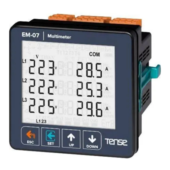
EM-07
USER MANUAL
RS485 Modbus RTU (1200 - 38400bps)
71.5 x 61.5 Custom Design Glass LCD
3-phase voltage and 3-phase current transformer.
It shows that V1,V2,V3 , V12, V23, V31, I1,I2, I3, S1,S2, S3, F1,F2, F3
It shows the minimum, maximum and average values of V1,V2,V3,V12,V23,V31,F1,F2, F3
It shows the minimum, maximum, average and demand values of I1,I2, I3, S1,S2, S3
High/Low voltage, current, frequency (adjustable)
Phase-Neutral or Phase-Phase protection (adjustable)
1x relay output
Protect Voltage, Current and Frequency
Shows phase sequence
You can delete the demands
Menu is password-protected.
Tense Electric Electronic
MADE IN TURKEY
Advertisement

Related Manuals for Tense EM-07


Summary of Contents for Tense EM-07
- Page 1 It shows the minimum, maximum, average and demand values of I1,I2, I3, S1,S2, S3 High/Low voltage, current, frequency (adjustable) Phase-Neutral or Phase-Phase protection (adjustable) 1x relay output Protect Voltage, Current and Frequency Shows phase sequence You can delete the demands Menu is password-protected. Tense Electric Electronic MADE IN TURKEY...
-
Page 2: Connection Diagrams
1 - Connection Diagrams: Figure-1 85-240VAC RS485 5A/250VAC 50/60Hz. <6VA Curent Transformer Connections Voltage Inputs Load Figure-1: 3P4W connection type: 3 phase current and 3 phase voltage and neutral. - Page 3 5 - General: EM-07 Multimeter measures the load on the system and voltage, current, apparent power minimum and maximum values, demands related to this load on the system.
- Page 4 6- Introduction of Home Screen: Mi n Ma x Av e Dm d E rr 8 Figure-2 1 - It shows phase number belong to measurement values 2 - Showing values are minimum of measurement values 3 - Showing values are maximum of measurement values 4 - Showing values are average of measurement values 5 - Showing values are demand of measurement values 6 - It shows Serial Communications...
-
Page 5: Error Code
8- Error Codes: Error Code Information Phase Sequence ERR Err0 If device in any case of error cut off, Relay will be open, backlight of display will be flashing and bottom right-hand High Voltage ERR Err1 corner of display will display ERR Code. Low Voltage ERR Err2 Err3... - Page 6 Out1 Out1 Out1 Out1 Out1 Figure-11 Figure-12 Figure-13 Figure-14 Figure-15 Figure-11: It shows the current values of each phase. The figure-12 is displayed when you press the Down button. Figure-12: It shows the minimum current values of each phase. The figure-13 is displayed when you press the Down button.
- Page 7 11 - To advance in Display Inventory: Out1 Out1 Out1 Out1 Home Figure-3 Figure-7 Figure-11 Screen Out1 Din1 Out1 Figure-21 Figure-16 The Home screen is displayed, when the device is energized. When you press the up button to see the other data on the display, the next data is displayed (Figure-3).
- Page 8 13.1 - Voltage Settings: Figure-26 Figure-32 Figure-33 Figure-34 Press Menu button and enter password (Default Password =0000) Figure-50 Figure-35 to enter program list. The figure-26 is displayed when you enter password and press the Menu button. You enter Voltage set when you press Menu button.
- Page 9 Pr.1 : High Voltage Protection Value: Determines the maximum operating voltage value of load. Default: 250V, Min: 1V, Max: 300V Figure-32 Pr.2: High Voltage Protection Delay Time: Determines delay open time. Delay time for activating the output. If any voltage exceeds high voltage protect value, Relay output switches open at the end of delay time.
- Page 10 Pr.11: Voltage Asymmetry Protection Value : Determines the controlled voltage asymmetry. Asymmetry Ratio Adjusment: Device calculates a value by dividing difference between highest and lowest phase value to highest phase value. Asymmetry Ratio = [(Highest Voltage – Lowest Voltage) / Highest Voltage ] x 100 Figure-42 Default: %20, Min: %5, Max: %30 Pr.12: Voltage Asymmetry Protection Delay time: Determines delay open time.
- Page 11 13.2 - Current Settings: Figure-27 Figure-51 Figure-52 Figure-53 Press Menu button and enter password (Default Password =0000) Figure-71 Figure-54 to enter program list. The figure-26(Voltage SET) is displayed when you enter password and press the Menu button. The figure-27 (Current SET) is displayed when you press the up button. You enter Current set when you press Menu button.
- Page 12 Pr.20: High Current Protection Value: Determines the maximum operating current value of load. Default: 3.0A, Min: 0.1A, Max: 5.0A Figure-51 Pr.21: High Current Protection Delay Time: Determines delay open time. Delay time for activating the output. If any current exceeds high current protect value, Relay output switches open at the end of delay time.
- Page 13 Pr.30: Current Asymmetry Protection Value: Determines the controlled current asymmetry. Asymmetry Ratio Adjusment: Device calculates a value by dividing difference between highest and lowest phase value to highest phase value. Default: %30, Min: %5, Max: %50 Figure-61 Pr.31: Current Asymmetry Protection Delay Time : Determines delay open time. Delay time for activating the output.
- Page 14 Pr.40: Demurrage Protection Factor: Demurrage current is 3-5 times more than normal operation current consumption. Ex: High current set value is :5A, demurrage protection factor is :1.5. Şekil-71 Max Demurrage current is 5x1.5=7.5 A so device will let motor use 35A for start up. Default: 3.0, Min: 1.0, Max: 10.0.
- Page 15 Pr.42: High Frequency Protection Delay Time: Determines delay open time. Delay time for activating the output. If any frequency exceeds high frequency protect value, Relay output switches open at the end of delay time. Default: 3sec, Min: 1sec, Max: 10000sec. Figure-73 Pr.43: High Frequency Protection Reset Time: Determines delay close time.
- Page 16 13.4 - RS485 RS485 Settings: Figure-29 Figure-83 Figure-84 Press Menu button and enter password to enter program list. The figure-26(Voltage SET) is displayed when you enter password and press the Menu button. The figure-27(Current SET) is displayed when you press the up button. The figure-28(Frequency SET) is displayed when you press the up button. The figure-29 (RS485 SET) is displayed when you press the up button.
- Page 17 Pr.55: Password Protection Enable/Disable: This menu is used for activating the user password. After the user password is activated for entering to the menus; if the Menu button is pressed, while the instant values are observed, user password is required. Default: Disable, Min: Disable, Max: Enable Figure-86 Pr.56: Phase Sequence Protection Enable/Disable: You can use device with phase...
- Page 18 15- Changing Password: Step 2 Step 3 Step 1 Step 1: Press Menu button and enter password to enter program list. The Voltage SET is displayed when you enter password and press the Menu button.Press “Up”button until you see the General SET Step 2: Pr.54 is displayed when you press the “SET”...
- Page 19 18- Low Voltage Protection Value Change: Step 1 Step 2 Step 3 Step 1: Press Menu button and enter password to enter program list. The Voltage SET is displayed when you enter password and press the Menu button. Step 2: Pr.1 is displayed when you press the “SET” button. and press “Up” button. You will see Pr.6. It is using for setting low voltage protection value.
- Page 20 21- Voltage Asymmetry Protection Value Change: Step 1 Step 2 Step 3 Step 1: Press Menu button and enter password to enter program list. The Voltage SET is displayed when you enter password and press the Menu button. Step 2: Pr.1 (HI V SET ) is displayed when you press the “SET” button and press “Up” button. You will see Pr.11.
- Page 21 24- Quick Setup : This section describes some of the most commonly used parameters. You can ajdust your system by apply them. These parameters are High/Low Voltage Protection value and hysteresis, Voltage Asymmetry protection value, High/Low Current Protection value and hysteresis, Current transformer ratio, demurrage factor and time. Press Menu button and enter password to enter program list.
- Page 22 Current SET menu is include set of high/low current protection,current transformer ratio and demurrage setings. Figure-27 Pr36 It is using for setting current transformer ratio. You can increase/decrease value to use Up/Down Button. You can use “SET” button to save. The figure-67 is displayed when you press the SET button.
-
Page 23: Parameters Table
25 - Parameters Table: Default Minimum Maximum Parameter Menu Parameter Unit Value Value Value Number Pr.1 High Voltage Value Volt Second Pr.2 High Voltage Delay Time 10000 Second Pr.3 High Voltage Reset Time 10000 Pr.4 High Voltage Hysteresis Volt Pr.5 High Voltage Protection Enable Disable... - Page 24 Muratpaşa Mah. Uluyol Cad. Cable Diameter 1.5mm² İşkent Sanayi Sitesi, E-Blok, 1.Kat Installation Front panel mounted BAYRAMPAŞA / ISTANBUL / TURKEY Tel: 0212 578 04 38 - 48 Fax: 0212 578 04 36 Operating Altitude <2000meters Web: www.tense.com.tr Mail: info@tense.com.tr -23-...
Need help?
Do you have a question about the EM-07 and is the answer not in the manual?
Questions and answers