DANA TM4 SUMO MD MV Troubleshooting Manual
Powertrain
Hide thumbs
Also See for TM4 SUMO MD MV:
- Installation manual (42 pages) ,
- Installation manual (42 pages)

Related Manuals for DANA TM4 SUMO MD MV


Summary of Contents for DANA TM4 SUMO MD MV
- Page 1 SUMO MD MV/HV Powertrain SUMO MD MV/HV Powertrain Troubleshooting Guide March 2021...
-
Page 2: Safety Warnings
Dana TM4 reserves the right to discontinue or modify materials recommended for use and should not be its models and/or procedures and to change considered an endorsement. - Page 3 Mishandling of this product may damage the product and/or cause injury or death. • limitations specifications communicated by Dana TM4 regarding the product must be respected. • Do not attempt to open, repair or modify the Motor Control Unit (MCU). In case of...
- Page 4 Safety Warnings WARNING CAUTION Regardless of the cooling system used, when in a It is important to ensure that no voltage is present on system, the MCU can be irreparably damaged and the high-voltage battery wires between both may become unstable if the coolant liquid pressure polarities and from each polarity to chassis before reaches or exceeds a pressure of 30 PSI (static manipulation.
-
Page 5: Table Of Contents
Safety Instructions ............ 8 TT18: High power battery voltage < lower voltage limit ................95 Dana TM4 Motor and MCU Components ....9 TT19: High Power Battery Voltage > Maximum ..99 System Specifications ..........10 TT20: IGBT Temperature Sensor reading over the Component Description .......... -
Page 6: General Information
General Information General Information Acronyms - Symbols TM4 ODIN Dana TM4 diagnostic software Ampere unit Universal Serial Bus Alternative Current Volt unit ACDC Alternative Current to Direct Vaux Auxiliary battery voltage (12 V or 24 V) Current Vehicle Management Unit... -
Page 7: Key Features
General Information Key Features Dana TM4 Motor Control Unit (MCU) Hazardous Voltage Interlock Loop (HVIL) The Motor Control Unit (MCU) system is operated via The Hazardous Voltage Interlock Loop (HVIL) internal CAN message communication between the MCU and loop is closed, resulting in a short circuit between its the Vehicle Management Unit (VMU) or Electronic two input pins. -
Page 8: Disclaimer
General Information Disclaimer When manipulating and/or installing this product, you Dana TM4 is not responsible for prolonged use of must NOT: product with one or more defective sensors as this could cause permanent damage to the product and • Modify any part of the MCU. -
Page 9: Dana Tm4 Motor And Mcu Components
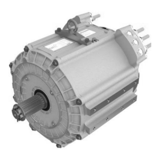
General Information Dana TM4 Motor and MCU Components (This is an example) Dana TM4 Motor Dana TM4 MCU... -
Page 10: System Specifications
General Information System Specifications The motorization system is composed of the MCU and The MCU has the following connectors: • motor. Communication connector. • Refer to the System Specification guide for your Grounding Point. • system. DC connectors. The table below is an example. •... -
Page 11: Component Description
General Information Component Description Communication connector An interface harness is used between the MCU and the VMU/ECU. The communication harness that is connected to the MCU contains all required signals to interface the MCU with the VMU/ECU, including the enable signal, the CAN ports and the CAN signals Type 2 connector The communication connector has 23 pins with the following specification:... - Page 12 General Information Type 1 connector The communication connector has 12 pins with the following specification: VMU/ECU interface harness – Plug pinout specifications – P770E0106 (Type1) Signal Name Types Description CAN1L Communication 20-22 Low level of differential signal CAN1. CAN1H Communication 20-22 High level of differential signal CAN1.
- Page 13 General Information Grounding Point The grounding point connection prevents functional The vehicle chassis connection points for the MCU issue to the motorization system, and ensures the and motor grounding straps should ideally be the user safety in case of an insulation fault. An incorrectly same point, or the same vehicle chassis frame side.
- Page 14 General Information Motor Phase Connectors Power cables are required between the MCU and the motor to connect each phase. An example of a product with a view of the phase cable connection points is shown below. Phase Cable Identification (Straight Terminal) Phase Cable Identification (90 degrees)
- Page 15 The Motor and the MCU must be connected together by motor sensor cables. Therefore, a motor sensor interface harness is required between the motor and the MCU. Motor sensor connector pinout mapping from Dana TM4 MCU to TM4 motors TM4 Motor TM4 Motor Signal name...
- Page 16 General Information Motor connector head Identification Dana TM4 MCU A3 (Type 2) Dana TM4 MCU A1/A2 (Type 1) Dana TM4 Motor (Type 2) Dana TM4 motor (Type 1)
- Page 17 General Information Connecting Auxiliary Battery to MCU Auxiliary Battery Fuse The Auxiliary Battery provides power to the MCU. The To protect the system against short circuit, a fuse is negative terminal of the battery must be connected to connected in series with the positive terminal of the the frame of the vehicle (chassis).
- Page 18 General Information Embedded software packages The software installation package includes several embedded files: • The embedded software package executable • A basic TM4 ODIN file (.odn4). The next chart shows the embedded software package files: File Name Description Embedded Software MCU_INV- ABCDEFGH Pkg.exe Embedded software files Package Executable...
- Page 19 General Information Coolant In / Out As power is delivered to the wheels, temperatures of the various components within the motor and the MCU rise. Therefore, a cooling unit/radiator must be installed in the vehicle and connected to the MCU and the motor to dissipate the excess heat.
- Page 20 General Information Coolant Specification Safety precaution As the cooling unit, cooling hose and cooling agent are not supplied by Dana TM4, the vehicle integrator WARNING has full responsibility for following specifications and operating methods given by the system specifications Regardless of the cooling system used, the product...
- Page 21 General Information WARNING User security: Allow for enough room for air circulation, clearance space for movement and access to cables for • Ensure that each cable is clearly identified for maintenance etc. specific usage to prevent errors during installation and operation that may damage When securing cables: the system or cause injury to the user.
- Page 22 The MCU requires a fuse on the High Voltage DC gland where the High Voltage battery (Traction bus. Proper fuse rating is necessary to protect Battery) is connected. against reverse polarity and short-circuit. Dana TM4 recommends installing a fuse with the following characteristics: The table below is an example.
-
Page 23: Simplified System Schematic
General Information Simplified System Schematic CAN interface (with DB9 connector) With TM4 ODIN installed Cooling source USB t o CA N Cooling int erf ace (pump and radiator) configuration connect or USB port Serial or Cooling parallel CAN interface Cooling in channel «... -
Page 24: Diagnostics
The latest version of TM4 ODIN can be downloaded from the Dana TM4 extranet: https://extranet.tm4.com/ Note: Contact Dana TM4 if there is any issue during the installation or configuration of TM4 ODIN. Note: We will refer the TM4 ODIN software by... - Page 25 Diagnostics Multimeter Megohmmeter Based upon system schematics and aided by This device is used to measure the insulation of high component-specific error messages, a multimeter is voltage equipment or installation that may present a required to check continuity, resistance and voltage safety hazard in the event of a fault.
-
Page 26: Installing The Can Drivers
Install all the CAN drivers provided with the CAN Connect the CAN ports of the CAN interface to the interface onto your computer. CAN port of the Dana TM4 product. Then connect the CAN interface to your computer. Note: You must have ADMIN access rights on your... -
Page 27: Opening Odin
“ODIN 4 Server 1” is preconfigured to communicate with a MCU product by default. “ODIN 4 Server 2” is preconfigured to communicate with a Dana TM4 NEURO (VMU) by default. The ODIN 4 Servers can be reconfigured to suit customer needs. - Page 28 Diagnostics Wait until ODIN loads the following page. Note: The following visual is an example. Other organization can be found has the software can be customized. In the « Diagnostic » dropdown menu, select « GDD » or click the icon in the tool bar. Note: GDD is also available and can be invoked if a CAN trace is required.
- Page 29 Diagnostics Note: The “Stop” button on the first window stops the CAN trace and gather the remaining information. At any time, you can click the “Abort” button on the second window to stop the process. Once the data has been gathered, the “Email Data” button on the first window becomes available.
- Page 30 Diagnostics Open the file. Count: SysFile counter. Event Code: SysFile ID. Event Description: Brief description of the SysFile ID. Event Data: This data gives precision about the cause of event. Time: Amount of time before the Event Code occurs (starting from each unit power up). DTC ID: Not used Purposed Actions: Not used...
-
Page 31: Sysfile Id Summary
Diagnostics SysFile ID Summary Table of Troubleshooting Tree Note: In this document Service Code are named The table of Troubleshooting Tree provides the SysFile ID in accordance with ODIN TM4 convention. information of the: • SysFile ID are described in the Service Codes SysFile ID, •... - Page 32 Diagnostics Table matching SysFile IDs and Troubleshooting Trees The following table relates the SysFile ID with the Troubleshooting Tree it belongs to. SysFile ID N° TT SysFile ID N° TT SysFile ID N° TT 0x0000 0x3201 0x4014 0x000A 0x3202 0x4015 0x0313 0x3203 0x4209...
-
Page 33: Troubleshooting Tips
Systems that are not provided or selected by Dana The most likely cause of electrical faults will be TM4 are not covered by this troubleshooting guide damaged wires or connections. As a first step in... -
Page 34: Service Codes
Service Codes Service Codes Abbreviation and Definition Abbreviation Name Description Tree that allows to diagnose the possible cause of an error, Troubleshooting Tree warning or information message given by the unit. Develops a specific and routine part of the troubleshooting tree. It Sub Troubleshooting Tree is used in multiple Troubleshooting Trees (TT). -
Page 35: Troubleshooting Tree Legends
Indicates a sub-tree present in this Sub-tree document. Process/Actions Indicates any process or action to do. Indicates a process we describe an assistance action (Ex: “Call Dana TM4 for Assistance Process help”). Indicates a decision point between two or Question/Decision/Choice more paths in the tree. -
Page 36: Tt01: Sysfile Cleared
« ReadyToPowerOff » state via CAN, the SysFile cleared. section could possibly get corrupted and will be cleared on the next power ON. Description Note: Refer to the Dana TM4 Product installation This SysFile ID is raised if the MCU is switch off guide more details installation before the “ReadyToPowerOff”... - Page 37 Service Codes...
-
Page 38: Tt02: Inconsistence In Eeprom Memory Section
Service Codes TT02: Inconsistence in EEPROM memory section System Mode Referred by Condition Possible Causes SysFile ID 1. Wrong shutdown sequence. Auxiliary vehicle battery (Vaux) (12V or 24V) powered OFF before the MCU “Ready To MCU was shut down 0x000A 0x1300 Shutdown. - Page 39 Service Codes...
-
Page 40: Tt03: Vaux Too Low
Service Codes TT03: Vaux too low System Mode Referred by Condition Possible Causes SysFile ID DCDC not regulating auxiliary DC voltage correctly. High auxiliary load being activated causing voltage drop. MCU detected an The auxiliary vehicle battery does not Operational 0x0313 auxiliary vehicle battery operate correctly. - Page 41 Service Codes VMU Connector Head Identification VMU/ECU Interface (Type 2) VMU/ECU Interface (Type 1) VMU/ECU interface harness Plug Pinout (Type 2) VMU/ECU interface harness Plug Pinout (Type1) Connector (Front) (Type 2) Connector (Front) (Type 1) Wire Insertion Side (Back) (Type 1) Wire Insertion Side (Back) (Type 2)
- Page 42 Service Codes Connector type 2 pinout Connector type 1 pinout...
- Page 43 Service Codes...
- Page 44 Service Codes...
- Page 45 Service Codes...
-
Page 46: Tt04: Vaux Too High
Service Codes TT04: Vaux too high System Mode Referred by Condition Possible Causes SysFile ID DCDC system not regulating auxiliary DC voltage correctly. Intermittent contact to the auxiliary MCU detected an vehicle battery that can cause voltage Operational 0x0314 auxiliary voltage that was spikes due to load dump of the DCDC too high. - Page 47 Service Codes Connector Head Identification VMU/ECU Interface (Type 2) VMU/ECU Interface (Type 1) VMU/ECU interface harness Plug Pinout (Type 2) VMU/ECU interface harness Plug Pinout (Type1) Connector (Front) (Type 2) Connector (Front) (Type 1) Wire Insertion Side (Back) (Type 1) Wire Insertion Side (Back) (Type 2)
- Page 48 Service Codes Connector type 2 pinout Connector type 1 pinout...
- Page 49 Service Codes...
- Page 50 Service Codes...
-
Page 51: Tt05: Hardware Failure Detected
Service Codes TT05: Hardware Failure Detected System Mode Referred by SysFile ID Condition Possible Causes 0x0315 0x0316 0x0321 Some foreign material within the MCU or 0x0322 0x0323 0x0324 motor connector short some signals. 0x0325 0x0326 0x2200 Internal MCU or motor connector pin is bent or 0x3109 0x3400 0x3401 Defective hardware fault... - Page 52 Service Codes Machine internal resistance measurement table...
- Page 53 Service Codes Connector Head Identification TM4 Motor connector (Type 1) TM4 Motor connector (Type 2)
- Page 54 Service Codes...
- Page 55 Service Codes...
- Page 56 Service Codes...
-
Page 57: Tt06: Abnormal Battery Current Condition
Service Codes TT06: Abnormal Battery Current Condition System Mode Referred by Condition Possible Causes SysFile ID 0x3113 error occurred at the same time that may lead to a defective MCU 0x050B error occurred at the same time DC battery current that may lead to an error at the VCU/ECU Operational 0x0319... - Page 58 Service Codes...
-
Page 59: Tt07: Phase Current Sensor Deactivated
Service Codes TT07: Phase Current Sensor Deactivated System Mode Referred by Condition Possible Causes SysFile ID If the 0x0313 SysFile occurred the same time this can be the main cause. 0x031A 0x031B Phase current sensor Operational Defective DCDC system. 0x031C deactivated. - Page 60 Service Codes Connector Head Identification VMU/ECU Interface (Type 2) VMU/ECU Interface (Type 1) VMU/ECU interface harness Plug Pinout (Type 2) VMU/ECU interface harness Plug Pinout (Type1) Connector (Front) (Type 2) Connector (Front) (Type 1) Wire Insertion Side (Back) (Type 1) Wire Insertion Side (Back) (Type 2)
- Page 61 Service Codes Connector type 2 pinout Connector type 1 pinout...
- Page 62 Service Codes...
- Page 63 Service Codes...
-
Page 64: Tt08: Hvil Voltage Input Fault
Service Codes TT08: HVIL voltage input fault System Mode Referred by Condition Possible Causes SysFile ID MCU HVIL parameters were not correctly configured. Another system opens the HVIL loop from The HVIL circuit had a the HVIL input of the MCU. Defective 0x031D current or voltage that... - Page 65 Service Codes Connector Head Identification VMU/ECU Interface (Type 2) VMU/ECU interface harness Plug Pinout (Type 2) Connector (Front) (Type 2) Wire Insertion Side (Back) (Type 2)
- Page 66 Service Codes Connector type 2 pinout...
- Page 67 Service Codes...
- Page 68 Service Codes...
-
Page 69: Tt09: Hvil Output Fault
Service Codes TT09: HVIL Output Fault System Mode Referred by Condition Possible Causes SysFile ID MCU HVIL parameters were not correctly configured. Another system opens the HVIL loop from The output of the HVIL the HVIL input of the MCU. Defective 0x031E line had a fault. - Page 70 Service Codes Connector Head Identification VMU/ECU Interface (Type 2) VMU/ECU interface harness Plug Pinout (Type 2) Connector (Front) (Type 2) Wire Insertion Side (Back) (Type 2)
- Page 71 Service Codes Connector type 2 pinout...
- Page 72 Service Codes...
- Page 73 Service Codes...
-
Page 74: Tt10: Internal Hvil Connection Fault
Service Codes TT10: Internal HVIL connection fault System Mode Referred by Condition Possible Causes SysFile ID MCU HVIL parameters were not properly configured. MCU phase cables not inserted properly with locking screws installed. Motor phase cables not inserted properly with locking screws installed. The HVIL line DC input cables not inserted properly with Defective... - Page 75 Service Codes...
- Page 76 Service Codes...
- Page 77 Service Codes...
-
Page 78: Tt11: Hvil Over Current
Service Codes TT11: HVIL over current System Mode Referred by Condition Possible Causes SysFile ID MCU HVIL parameters were not properly configured. HVIL over current fault Defective 0x0320 HVIL power source fault. was detected. Defective MCU. HVIL The HVIL is short for “High Voltage Interlock Loop”. To correctly diagnose the faulty system, connect the HVIL is a hardware signal, and its purpose is to Diagnostic Tool (see «Diagnostics»... - Page 79 Service Codes Connector Head Identification VMU/ECU Interface (Type 2) VMU/ECU Interface (Type 1) VMU/ECU interface harness Plug Pinout (Type 2) VMU/ECU interface harness Plug Pinout (Type1) Connector (Front) (Type 2) Connector (Front) (Type 1) Wire Insertion Side (Back) (Type 1) Wire Insertion Side (Back) (Type 2)
- Page 80 Service Codes...
- Page 81 Service Codes...
-
Page 82: Tt12: Initialization Timed Out
MCU. In this case, check the correct software version from Dana TM4 extranet. The correct software version must be flashed to the MCU. The user must access the Dana TM4 Extranet to determine which software versions are compatible with the particular 4. - Page 83 Service Codes...
- Page 84 Service Codes...
-
Page 85: Tt13: Invalid Motor Type Or Phase Calibration
Service Codes TT13: Invalid Motor Type or Phase Calibration Referred by System Mode Condition Possible Causes SysFile ID Invalid motor type or Third party motor not calibrated. Defective 0x120A 0x3212 phase calibration. Defective motor. Description The Troubleshooting Tree 13 indicates an error where the Initialization of the Motor Control Unit (MCU) timed out, and couldn’t be completed. - Page 86 Service Codes...
-
Page 87: Tt14: Invalid Hardware Version
2. The software version flashed to the MCU was incorrect. In this case, the user must go to the Dana TM4 extranet to find a compatible software version, and then flash it to the MCU. Refer to the Appendix 6: Update Software for the procedure to do this. - Page 88 Service Codes...
-
Page 89: Tt15: Inconsistence Of Protected Eeprom Memory Section
Service Codes TT15: Inconsistence of Protected EEPROM memory section Referred by System Mode Condition Possible Causes SysFile ID Inconsistency of the Protected, Global or 0x1000 0x1100 ParamDrv EEPROM Defective Defective MCU. 0x1200 memory section has been detected through a CRC verification. - Page 90 Service Codes...
-
Page 91: Tt16: Invalid Hardware Or Software
Note: Refer to the MCU installation guide for more details on installation and deinstallation procedure including safety warning considerations. Note: Replace the MCU with a MCU corresponding to the MCU subfolder specified on the Dana TM4 extranet site. - Page 92 Service Codes...
-
Page 93: Tt17: Inconsistence Between Control Logic And Igbt
Service Codes TT17: Inconsistence between Control Logic and IGBT Referred by System Mode Condition Possible Causes SysFile ID Minor issue. Could potentially be raised due to internal noise under high DC input Inconsistency between 0x3100 0x3101 voltage level. the internal control logic 0x3102 0x3103 Defective MCU, if 0x320D SysFile ID Operational... - Page 94 Service Codes...
-
Page 95: Tt18: High Power Battery Voltage < Lower Voltage Limit
Service Codes TT18: High power battery voltage < lower voltage limit Referred by System Mode Condition Possible Causes SysFile ID DC high power contactor issue. DC high power battery source issue. DC high power battery chain connection The high-power DC issue (contactor, PDU, pre-charge circuit and voltage dropped under Defective... - Page 96 Service Codes...
- Page 97 Service Codes...
- Page 98 Service Codes...
-
Page 99: Tt19: High Power Battery Voltage > Maximum
Service Codes TT19: High Power Battery Voltage > Maximum Referred by System Mode Condition Possible Causes SysFile ID “BlackBox info available” is not displayed in the status bar at the bottom of the window in TM4 ODIN tool Significant voltage drops meaning numerous repeated connections and reconnections. - Page 100 Service Codes Note: Regarding the resolver angle waveform, if the MCU goes in faulty state, it will capture a BlackBox upon the reported error(s). The BlackBox can then be consulted via ODIN tool to see if the angle waveform (saw tooth) is straight on each rising and falling edges.
- Page 101 Service Codes...
- Page 102 Service Codes...
- Page 103 Service Codes...
- Page 104 Service Codes...
-
Page 105: Tt20: Igbt Temperature Sensor Reading Over The Limit
Service Codes TT20: IGBT Temperature Sensor reading over the limit Referred by System Mode Condition Possible Causes SysFile ID Air in the cooling circuit. Cooling liquid flow too low or nil (cooling pump issue). Cooling liquid temperature too high One of the temperature Wrong cooling agent mixture used –... - Page 106 Service Codes...
-
Page 107: Tt21: Temperature Sensor Reading Over The Limit
Service Codes TT21: Temperature Sensor reading over the limit Referred by System Mode Condition Possible Causes SysFile ID Air in the cooling circuit. Cooling liquid flow too low or nil (cooling One of the internal pump issue). temperature sensors Defective went over the limit and Cooling liquid temperature too high. - Page 108 Service Codes...
-
Page 109: Tt22: Emi Temperature Measurement Over Limit
Service Codes TT22: EMI Temperature measurement over limit Referred by System Mode Condition Possible Causes SysFile ID Air in the cooling circuit. Cooling liquid flow too low or nil (cooling pump issue). The internal EMI section Cooling liquid temperature too high. temperature Wrong cooling agent mixture used –... - Page 110 Service Codes...
-
Page 111: Tt23: Motor Coil Temperature Sensor Measurement Over Limit
Service Codes TT23: Motor Coil Temperature Sensor measurement over limit Referred by System Mode Condition Possible Causes SysFile ID Another SysFile occurred (TT05) Air in the cooling circuit. Cooling liquid flow too low or nil (cooling pump issue). One of the temperature sensors of the motor coil Cooling liquid temperature too high Wrong cooling agent mixture used –... - Page 112 Service Codes...
-
Page 113: Tt24: High Resolver Temperature
Service Codes TT24: High Resolver Temperature Referred by System Mode Condition Possible Causes SysFile ID Air in the cooling circuit. Cooling liquid flow too low or nil (cooling The Resolver Converter pump issue). Operational Chip detected a resolver Cooling liquid temperature too high. 0x3405 Wrong cooling agent mixture used –... - Page 114 Service Codes...
-
Page 115: Tt25: Internal Software Command Not Received Properly
These SysFile IDs is a software version issue. The user must update the software of the MCU to the last version published in Dana TM4 extranet. The MCU itself may also be defective. To correctly diagnose the faulty system, connect the Diagnostic Tool (see «Diagnostics»... - Page 116 Service Codes...
-
Page 117: Tt26: Igbt Short Circuit Activated
Service Codes TT26: IGBT Short Circuit Activated Referred by System Mode Condition Possible Causes SysFile ID The IGBT short circuit Other error causes the system to move in mechanism has been defective while in high speed (back EMF Operational activated. This event is 0x3113 too high to maintain DC bus under the high normally a reaction to... - Page 118 Service Codes...
-
Page 119: Tt27: Phase Current Reached Maximum
Service Codes TT27: Phase Current reached Maximum Referred by System Mode Condition Possible Causes SysFile ID Short circuit between phases. The auxiliary vehicle battery not operating correctly. 0x3200 0x3201 One or more of the phase Intermittent or bad Vaux connection at the 0x3202 0x3204 currents reached the MCU. - Page 120 Service Codes...
-
Page 121: Tt28: Phase Current Sum Reached Maximum
Service Codes TT28: Phase Current Sum reached Maximum Referred by System Mode Condition Possible Causes SysFile ID The auxiliary vehicle battery not operating correctly. The phase 1-2-3, 4-5-6, Intermittent or bad Vaux connection at the or 7-8-9 current sum 0x3203 0x3207 Operational MCU. - Page 122 Service Codes...
-
Page 123: Tt29: Insufficient Defluxing Current At High Speed123
Service Codes TT29: Insufficient Defluxing Current at high speed Referred by System Mode Condition Possible Causes SysFile ID MCU temperature too high for the motor speed (verify cooling). There is not enough Motor temperature too high for the motor Defective defluxing current at high 0x320C speed (verify cooling). - Page 124 Service Codes...
- Page 125 Service Codes References...
-
Page 126: Tt30: Ac Current - Torque Mismatch
Note: Refer to the motor installation guide for more details on installation and deinstallation procedure including safety warning considerations. Note: Refer to the Dana TM4 product(s) MCU installation guide(s) for more details on installation and deinstallation procedure including safety warning... - Page 127 Service Codes Note: Regarding the resolver angle waveform, if the MCU goes in faulty state, it will capture a BlackBox upon the reported error(s). The BlackBox can then be consulted via ODIN tool to see if the angle waveform (saw tooth) is straight on each rising and falling edges.
- Page 128 Service Codes...
- Page 129 Service Codes...
- Page 130 Service Codes...
- Page 131 Service Codes...
- Page 132 Service Codes...
-
Page 133: Tt31: Phase Cable(S) Shorted To Chassis
Defective motor. Description The Troubleshooting Tree 31 indicates an error where Note: Refer to the Dana TM4 Product installation the cables (AC or DC) connecting the Motor and the guides for more details on installation and deinstallation MCU were shorted to the chassis, possibly due to a procedure including safety warning considerations. - Page 134 Service Codes...
- Page 135 Service Codes...
- Page 136 Service Codes...
- Page 137 Service Codes...
- Page 138 Service Codes...
-
Page 139: Tt32: Motor Speed Reached Maximum
Service Codes TT32: Motor Speed reached Maximum Referred by System Mode Condition Possible Causes SysFile ID Motor speed is too high - Torque derated but something else preventing the speed The motor speed to reduce. reached its limit in forward or backward MCU speed setting parameters wrongly Defective 0x3210 0x3211... - Page 140 Service Codes Note: Regarding the resolver angle waveform, if the MCU goes in faulty state, it will capture a BlackBox upon the reported error(s). The BlackBox can then be consulted via ODIN tool to see if the angle waveform (saw tooth) is straight on each rising and falling edges.
- Page 141 Service Codes...
- Page 142 Service Codes...
-
Page 143: Tt33: Critical Low Frequency Process Overrun
Note: regarding this type of error If the software is the latest version as published on the Dana TM4 extranet site and this error is listed at > 0:00 second after the « Info – System power-up » event, this indicates that there is an issue with the... - Page 144 Service Codes...
-
Page 145: Tt34: Vmu Command Out-Of-Range Or Invalid
The command did not match what was required by the CAN protocol. The CAN network might cause the issue fixed. Refer to the CAN protocol document published on the Dana TM4 extranet site. Note: Refer to the CAN protocol document as published on the Dana TM4 extranet site. - Page 146 Service Codes...
-
Page 147: Tt35: Can Communication Error
CAN communications. The CAN network might cause the issue fixed. Refer to the CAN protocol document published on the Dana TM4 extranet site. The MCU itself may be defective. Note: Refer to the CAN protocol document as published on the Dana TM4 extranet site. - Page 148 Service Codes Connector type 1 and type 2 pinouts. Expected resistance measurement between CAN ports.
- Page 149 Service Codes...
- Page 150 Service Codes...
-
Page 151: Tt36: Position And/Or Temperature Sensor Error
Service Codes TT36: Position and/or Temperature Sensor Error Referred by System Mode Condition Possible Causes SysFile ID Deactivation process The VMU/ECU has sent a shutdown couldn't be successfully request to the MCU during operation, Operational executed or timeout 0x050B 0x050C causing this error to be raised. - Page 152 Service Codes...
-
Page 153: Tt37: Sequencer Error
Service Codes TT37: Sequencer error Referred by System Mode Condition Possible Causes SysFile ID 0x0506 0x0507 This error is activated by Some other error caused the SysFile to Operational 0x0508 0x0509 a lower level error. be raised. 0x050A 0x050D Description The event category 37 shows a sequencer type error. - Page 154 Service Codes...
-
Page 155: Stt01: Verify Connector Integrity
Service Codes STT01: Verify Connector Integrity Related TT External input Outcome TT03 TT04 TT05 TT08 None. The connectors have been replaced. TT09 TT10 TT27 TT28 Description The sub troubleshooting tree “Verify Connector Note: Refer to the TM4 Product installation guide for Integrity”... - Page 156 Service Codes...
-
Page 157: Stt02: Verify Cooling Circuit Integrity
Service Codes STT02: Verify Cooling Circuit Integrity Related TT External input Outcome 1. The cooling system has no problems and can be left alone. 2. The cooling hoses have a problem and must be TT20 TT21 TT22 TT23 TT24 TT29 physically oved or replaced. - Page 158 Service Codes...
- Page 159 Service Codes...
-
Page 160: Appendix
Appendix Appendix Appendix 1: Table of SysFile ID The following table of the SysFile ID gives the in formation of the diagnostic type, the code description and the related Troubleshooting Tree. SysFile Diagnostic Description Troubleshooting Type Tree 0x0000 SysFile 0x0000 - SysFile cleared Info 0x000A Warning... - Page 161 Appendix SysFile Diagnostic Description Troubleshooting Type Tree 0x2200 Warning ParamMac 0x00 0x2209 Error ParamMac 0x09 - Unsupported motor hardware version 0X3100 Warning Motor Control Inverter 0x00 0X3101 Warning Motor Control Inverter 0x01 0x3102 Warning Motor Control Inverter 0x02 0x3103 Warning Motor Control Inverter 0x03 0x3104 Warning...
- Page 162 Appendix SysFile Diagnostic Description Troubleshooting Type Tree 0x3206 Error Motor Control Machine 0x06 - MCU phase #6 current reached the maximum 0x3207 Warning Motor Control Machine 0x07 - Sum of MCU phase #4_5_6 currents exceeds maximum limit 0x3208 Error Motor Control Machine 0x08 - MCU phase #7 current reached the maximum 0x3209 Error...
- Page 163 Appendix SysFile Diagnostic Description Troubleshooting Type Tree 0x4003 Warning ComClient 0x03 VmuCommandSafety CommandMode is invalid 0x4004 Warning ComClient 0x04 VmuCommand2 TorqueCommand is out of range 0x4005 Warning ComClient 0x05 VmuCommand2 SpeedCommand is out of range 0x4006 Warning ComClient 0x06 - VmuCommand2 CommandMode is invalid 0x4007 Warning...
- Page 164 Appendix SysFile Diagnostic Description Troubleshooting Type Tree Sequencer 0x0B – Deactivation failed. This vent 0x050B Error indicates that the deactivation process couldn’t be successfully executed. Sequencer 0x0C – Deactivation timed out. This 0x050C Error event indicates that a timeout occurred while going in the deactivation process.
-
Page 165: Appendix 2: Table Of Troubleshooting Trees
Appendix Appendix 2: Table of Troubleshooting Trees The following table of the SysFile ID gives the in formation of the diagnostic type, the code description and the related Troubleshooting Tree. Troubleshooting SysFile IDs Causes (numbered in order of likely occurrence) Tree 1. - Page 166 Appendix Troubleshooting SysFile IDs Causes (numbered in order of likely occurrence) Tree Some foreign material within the MCU or motor connector short 0x0315 some signals. 0x0316 2. MCU or motor connector pin is bent or broken. 0x0321 3. Motor sensor cable defective. 0x0322 4.
- Page 167 Appendix Troubleshooting SysFile IDs Causes (numbered in order of likely occurrence) Tree 1. MCU HVIL parameters were not properly configured. 0x031F 2. MCU phase cables not inserted properly with locking screws installed. 3. Motor phase cables not inserted properly with locking screws installed.
- Page 168 Appendix Troubleshooting SysFile IDs Causes (numbered in order of likely occurrence) Tree 0x3107 0x3108 1. DC high power contactor issue. 0x310A 2. DC high power battery source issue. 3. DC high power battery chain connection issue (contactor, PDU, pre- charge circuit and MCU, BMS). 4.
- Page 169 Appendix Troubleshooting SysFile IDs Causes (numbered in order of likely occurrence) Tree 1. Air in the cooling circuit. 0x3405 2. Cooling liquid flow too low or nil (cooling pump issue). 3. Cooling liquid temperature too high. 4. Wrong cooling agent mixture used – (can create dust/rust in the cooling circuit.
- Page 170 Appendix Troubleshooting SysFile IDs Causes (numbered in order of likely occurrence) Tree 1. Motor speed is too high - Torque derated but something else 0x3210 preventing the speed to reduce. 0x3211 2. MCU speed setting parameters wrongly configured (start, end and speed limit derating in forward or backward direction).
-
Page 171: Appendix 3: Save Eeprom Sections
Appendix Appendix 3: Save EEPROM Sections Power-on the unit with appropriate Vaux supply Open Odin Server 1 and establish connection to the MCU. Make sure that at the bottom left of the Odin screen, « Device Connected » is displayed in green text. -
Page 172: Appendix 4: Retrieve Gdd Files And User Parameters
Note: This will allow you to select the location of where the Motor Control Unit GDD (Gathered Diagnostic Data) File will be saved. Note: If you didn’t succeed to retrieve the GDD Files and user parameters, notify to Dana TM4 and continue further down the troubleshooting tree... - Page 173 Appendix Open Odin Server 1 and establish connection to the ACDC controller of the unit. Make sure that at the bottom left of the Odin screen the message, « Device Connected », shows up green. In Odin Server 1, in the « Package Files » dropdown menu, select «...
- Page 174 Appendix Wait until TM4 ODIN load the following page. Make sure you are connected to the product using TM4 ODIN by checking that the bottom left of the Odin screen, « Device Connected » is displayed in green text. 10. In the « Diagnostic » dropdown menu, select «...
- Page 175 Appendix 11. Wait until TM4 ODIN load the following page. 12. On the Parameters Tab, right click the select “Export Values To File…”.
-
Page 176: Appendix 5: Cooling Agent Precautions
Appendix Appendix 5: Cooling agent precautions Safety precaution Safety precaution WARNING In case of contact with eyes and skin, rinse with water and consult a doctor. • In case of ingestion, seek medical help It is mandatory to proceed with caution when connecting and disconnecting the system. -
Page 177: Appendix 6: Update Software
15. Contact TM4 Customer Service if you require help Download the up to date software from the programming the system using TM4 ODIN. Dana TM4 extranet site. 2. Once downloaded, execute the software package exe file. The appropriate file will be saved at the right location on the PC for ODIN usage. - Page 178 Appendix Remove electrical connections Safety precaution WARNING Safety instructions related electrical This product uses differential mode capacitors removal/installation: between the positive high-voltage DC bus (+) and the negative high-voltage DC bus (-). Even when the Electrical connections should be handled by fully product is disconnected from the high-voltage source, trained personnel.
- Page 179 Appendix Remove the MCU from the vehicle Install the new unit Safety precaution Safety precaution Safety instructions related to the charger removal: WARNING WARNING Mishandling of this product may damage the product and/or cause injury or death. Follow the vehicle integrator’s instructions to unmount •...
- Page 180 Appendix Prepare and pack defective unit for shipping CAUTION This section describes the conditions that must be adhered to transporting TM4 products in order to ensure optimum performance once installed in a vehicle. On leaving TM4 facilities, the product is void of all coolant and all connectors are covered.
- Page 181 This page intentionally left blank.
- Page 182 For spec‘ing or service assistance, call 1-877-777-5360 or visit our website at http://www.dana.com Dana TM4 inc. 135, Joseph-Armand Bombardier, #25 Boucherville (Québec) J4B 8P1 Canada www.dana.com/TM4 All applications must be approved by the Application Engineering Department. Specifications and/or design are subject to change without notice or obligation.
Need help?
Do you have a question about the TM4 SUMO MD MV and is the answer not in the manual?
Questions and answers