
Related Manuals for Volvo D12


Summary of Contents for Volvo D12
- Page 1 Service Manual Trucks 250–600 Group Intake and Exhaust System D12, D12A, D12B, D12C PV776-TSP144524...
- Page 2 Greensboro, NC USA Order number: PV776-TSP144524 © 2000 Volvo Trucks North America, Inc., Greensboro, NC USA All rights reserved. No part of this publication may be reproduced, stored in retrieval system, or transmitted in any forms by any means, electronic, me- chanical, photocopying, recording or otherwise, without the prior written permission of Volvo Trucks North America, Inc..
-
Page 3: Table Of Contents
Contents General ....................3 Specifications ..................5 Intake and Exhaust System ..............5 Tools ......................7 Special Tools ..................7 Special Equipment ................. 8 Design and Function ................9 Intake and Exhaust System ..............9 Preheater ....................9 D12C ....................9 Engines without Preheater .............. -
Page 5: General
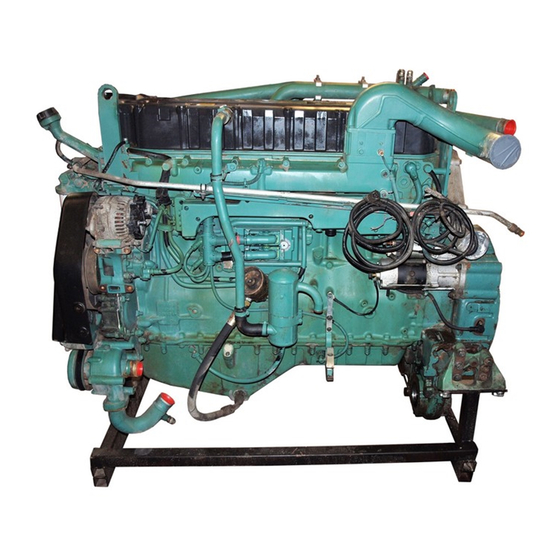
Group 25 Intake and Exhaust System General General W2003244 D12C Engine This information covers the Intake and Exhaust System for the D12, D12A, D12B, and D12C engines. -
Page 7: Specifications
Group 25 Intake and Exhaust System Specifications Specifications Intake and Exhaust System Maximum Restriction (Rated speed full load) ................6.2 kPa (H 2 0) (25 in.) Air Cleaner torque Plastic ............................9 ± 2 Nm (7 ± 2 ft–lbs) Metal ............................20 ± 2 Nm (15 ± 2 ft-lbs) For Specifications, including torques, refer to: Service Manuals 200–890, Specifications, D12C... - Page 8 Group 25 Intake and Exhaust System Specifications...
-
Page 9: Tools
Tools Special Tools Servicing the VE D12 intake and exhaust systems requires the following special tools. The tools are available from parts departments of Volvo Trucks North America, Inc. When requesting tools, provide the appropriate number, preceded by ”999”, for exam- ple, 9992610. -
Page 10: Special Equipment
Group 25 Intake and Exhaust System Tools Special Equipment Like the special tools, the following are available from the parts department of Volvo Trucks North America, Inc.. When requesting tools, provide the appropriate part num- ber. W0001840 1159794 Torque wrench 10–100 Nm (7–73 ft-lb) -
Page 11: Design And Function
Design and Function Intake and Exhaust System Preheater Selected versions of the D12 are equipped with a pre- heater. Its purpose is to warm air in the intake manifold when starting the engine. This heated air eases starting at very low temperatures and reduces engine smoking when starting a cold engine. -
Page 12: Engines Without Preheater
Group 25 Intake and Exhaust System Design and Function Engines without Preheater On engines not equipped with a preheater, engine coolant temperature determines the point at which fuel injection begins while starting. The crankshaft rotates an extra number of turns to increase cylinder temperature before fuel injection begins. -
Page 13: Engine Brake
Rocker arm Shutter Control valve Exhaust pressure governor Shim The Volvo Engine Brake (VEB) is a combination of two brake systems: the exhaust brake and the compression brake. Exhaust brake The exhaust pressure governor uses a shutter mounted in the exhaust outlet from the turbocharger. This shutter, connected to the exhaust pressure governor plunger, can restrict the exhaust gas flow. -
Page 14: D12C
Group 25 Intake and Exhaust System Design and Function D12C The VEB solenoid has been moved to the center of the rocker shaft. The oil supply is internal, rather than having the external piping visible. Control Valve The control valve is mounted on the cylinder head under the valve cover, and is connected to the oil system ahead of the rocker arm shaft. - Page 15 Group 25 Intake and Exhaust System Design and Function Camshaft on Engine with Compression Brake The camshaft on an engine with a compression brake has an induction lobe (1) and a decompression lobe (2) — in addition to the normal exhaust lobe (3) — on each cam profile for the exhaust valves.
- Page 16 Group 25 Intake and Exhaust System Design and Function Exhaust Rocker Arms The exhaust rocker arms on an engine with a compres- sion brake are larger than those on a conventional engine. The rocker arm includes a non-return valve (2) and a plunger (3) with a pressure limiting valve, the purpose of which is to regulate the oil flow during compression brak- ing.
- Page 17 Group 25 Intake and Exhaust System Design and Function Rocker Arm Plunger The purpose of the rocker arm plunger is to eliminate all valve clearance during the compression braking. Engine Operation When the engine is operating (compression brake not activated), there is reduced oil pressure — approx. 100 kPa (14.5 psi) —...
- Page 18 Group 25 Intake and Exhaust System Design and Function Control System The engine brake is connected to the throttle pedal and is activated when the pedal is completely released, ac- cording to the selection made with the engine brake switch on the instrument panel. The selection made with this switch also regulates en- gine braking activated by the cruise control.
- Page 19 Group 25 Intake and Exhaust System Design and Function Compression Brake The exhaust brake is always engaged in conjunction with the compression brake. In the compression brake induction phase, the exhaust brake creates an overpres- sure in the exhaust manifold, making the compression brake more efficient.
-
Page 20: Crankcase Ventilation
Group 25 Intake and Exhaust System Design and Function Crankcase Ventilation D12C The D12C has new crankcase ventilation with its outlet from the upper timing gear cover. The timing gear cover is designed with an oil trap to pre- vent oil from escaping through the ventilation tube. T2012791 Fig. -
Page 21: Exhaust Pressure Governor
Volvo Engine Brake, or VEB (both exhaust brake and compression brake). Engines with Exhaust Brake Only... - Page 22 Group 25 Intake and Exhaust System Design and Function Engines with VEB When the engine brake ON/OFF switch is in the ON po- sition, the engine brake is activated according to the position of the engine brake HI/LO switch. With the HI/LO switch in the LO position, only the ex- haust pressure governor is activated and is subject to the same conditions as for engines with an exhaust brake only.
-
Page 23: D12C
Group 25 Intake and Exhaust System Design and Function D12C The EPG on the D12C has a new air valve. The valve is located on the right, rear edge of the engine block and is controlled by current from the EECU. There are two on/off valves and two reduction valves in the valve body. -
Page 24: Epg Control Valve
Group 25 Intake and Exhaust System Design and Function EPG Control Valve The exhaust pressure governor is controlled by a valve that regulates air pressure to the EPG. The exhaust pressure governor operates using two dif- ferent pressures: • When the exhaust pressure governor is activated during starting and keeping the engine warm, the control valve provides a control pressure of approxi- mately 200 kPa (29 psi). -
Page 25: Air Restriction Indicator
Group 25 Intake and Exhaust System Design and Function Air Restriction Indicator There are several types of restriction indicators which can be mounted in certain locations, such as on the air cleaner duct or on/above the instrument panel. The air restriction indicator mounted on the instrument panel permits continuous monitoring of the gauge. -
Page 26: Turbocharger
— but not before it has been cooled down after passing through the charge air cooler. T2006949 Fig. 28: Turbocharger D12A The turbo used on the D12A engine is NOT interchange- able with turbos on other D12 engine versions. -
Page 27: Exhaust Manifold
Group 25 Intake and Exhaust System Design and Function Exhaust Manifold New design of exhaust manifold sections W2002222 Fig. 29: Manifold designs Description New design P/N Old design P/N Side section 3964707 1547521 Middle section 3964708 1547520 Complete 3964706 1677205 Improved gasket W2002223 Fig. -
Page 28: Tightening Sequence
Group 25 Intake and Exhaust System Design and Function Tightening Sequence Old Style Manifold. New Style Manifold T2012896 W2002224... -
Page 29: Troubleshooting
Group 25 Intake and Exhaust System Troubleshooting Troubleshooting Air Restriction Indicator, Checking Low restriction readings may be difficult to identify. They can result from a damaged element gasket, ruptured element, incorrectly installed element or a leak in the en- gine air intake ducts and piping. When servicing the air cleaner, make sure to check for these. -
Page 31: Service Procedures
Group 25 Intake and Exhaust System Service Procedures Service Procedures 2562-03-02-01 Air Filter Element, Replacement Before working on a vehicle, set the parking brakes, place the transmission in neutral, and block the wheels. Failure to do so can result in unexpected vehicle movement and can cause serious personal in- jury or death. -
Page 32: Intake Manifold Gasket(S), Replacement
Group 25 Intake and Exhaust System Service Procedures W2000746 Fig. 34: Endcap reinstall Reinstall the endcap and attach, using 24 ± 2 Nm W2000941 Fig. 33: Remove the air filter (WG, AC) the necessary hardware. Tighten to a (18 ± 2 ft-lb) torque of 24 ±... -
Page 33: Removal
Group 25 Intake and Exhaust System Service Procedures W2000733 Fig. 36: Replacing intake manifold gasket Remove the intake manifold bolts and W2000732 carefully tap the manifold loose, using Fig. 35: Replacing intake manifold gasket a plastic-headed mallet. Removal Clean the sealing surfaces of the in- Remove the plastic ties from the elec- take manifold and the cylinder head. -
Page 34: Turbocharger, Replacement
Group 25 Intake and Exhaust System Service Procedures W2000943 W2000734 Fig. 38: Turbocharger assembly Fig. 37: Replacing intake manifold gasket Adjust the alternator, A/C refrigerant compressor, drive belt tension if so Exhaust pressure governor equipped. Oil delivery and return pipes Clamp Nuts Install the pre-heater (if equipped) or... -
Page 35: Installation
Group 25 Intake and Exhaust System Service Procedures Remove the bolts holding the charge air pipe to the mounting bracket. Pull Before installing the new turbocharger, the charge air pipe off the tur- check the engine oil and change the bocharger. -
Page 36: Exhaust Manifold Gasket(S), Replacement
Group 25 Intake and Exhaust System Service Procedures Removal Reconnect the air cleaner hose to the turbocharger. Remove the bolts holding the exhaust manifold and lift off the manifold. Attach the turbocharger oil return pipe, using new seals. Disassemble the exhaust manifold and remove all sealing rings. -
Page 37: Exhaust Pressure Governor, Replacement
Group 25 Intake and Exhaust System Service Procedures Start the engine and run until it reaches operating temperature. Verify the torque at 48 ± 8 Nm (35 ± 6 ft-lb). 2538-03-02-01 Exhaust Pressure Governor, Replacement T2006940 Fig. 42: Removing air pressure governor Remove the bolts and lift off the ex- Before working on a vehicle, set the parking brakes, place the transmission in neutral, and block the... -
Page 38: Exhaust Pressure Governor, Overhaul
Group 25 Intake and Exhaust System Service Procedures 2538-04-04-01 Disassembly Exhaust Pressure Governor, Remove the end cover from above the Overhaul plunger. (Unit Removed) Remove the bolts and take out the plunger. Before working on a vehicle, set the parking brakes, place the transmission in neutral, and block the wheels. -
Page 39: Assembly
Group 25 Intake and Exhaust System Service Procedures Remove the bolts holding the cover, the heat shield and the securing flange. T2006746 Fig. 48: Plunger rod installation Put the plunger rod onto drift 9992610 9992610 in a press. Using drift 9998225, press 9998225 on the spring holder until it bottoms in T2006744... - Page 40 Group 25 Intake and Exhaust System Service Procedures Install the set screw into the plunger 40 ± 5 Nm rod. Apply sealant to the set screw be- (30 ± 4 ft-lb) fore installing. Tighten the set screw to 40 ± 5 Nm (30 ± 4 ft-lb). Install a new seal into the plunger rod 13 ±...
-
Page 41: Charge Air Cooler Leak Test, Checking
Group 25 Intake and Exhaust System Service Procedures 2651-06-04-01 WARNING Charge Air Cooler Leak Test, Checking Make sure that the gauge pressure never exceeds 100 kPa (14.5 psi). Failure to do so can result in personal injury. If the turobocharger fails on an intercooled engine, it is essential to check the charge air cooler. - Page 42 Group 25 Intake and Exhaust System Service Procedures W2000735 Fig. 51: Removing charge air hoses Remove the air hoses from the charge 9998288 air cooler. Install connecting washer 9998289 9998288, sealing washer 9998289 and new O-rings. W2000736 Fig. 52: Connecting pressure gauge Remove the pressure gauge reduction valve and check that the gauge read- ing is “0.”...
-
Page 43: System Check
Note: For a reliable result, engine load must be maintained long enough for the pressure to stabilize. Boost pres- sure specifications at 28.3 r/s (1700 rpm): • VE D12–370 125–170 kPa (18–24.7 psi) • VE D12–415 145–175 kPa ( 21–25.4 psi) -
Page 44: Exhaust Backpressure, Checking
Group 25 Intake and Exhaust System System Check Exhaust Backpressure, Checking Pressure gauge: Of indicating or U-tube type, graded to 24 kPa or 2,440 mm water column (3.5 psi) and equipped with damper. Steel pipe: About 200 mm (8 in.) long and able to con- nect to a union. -
Page 45: Feedback
If you have any comments or suggestions, make a copy of this page, write down your comments and send them to us, either via telefax or mailing directly to the address listed below. From Volvo Trucks North America, Inc................Dept. 516 Service Publications ................ - Page 47 Operation Numbers 2512-03-02-01 Intake Manifold Gasket(s), Replacement ..... 30 2516-03-04-01 Exhaust Manifold Gasket(s), Replacement ....34 2538-03-02-01 Exhaust Pressure Governor, Replacement .
- Page 48 Volvo Trucks North America, Inc. P.O. Box 26115, Greensboro, NC 27402-6115 Volvo Trucks Canada, Ltd. 6490 Vipond Drive, Mississauga, Ontario L5T 1W8 http://www.volvotrucks.volvo.com PV776-TSP144524 (300) 08.200 © Volvo Trucks North America, Inc., 2000...
Need help?
Do you have a question about the D12 and is the answer not in the manual?
Questions and answers
Fuga persistente de gasóleo no motor D12A
João André Antônio