Table of Contents
Advertisement
Quick Links
Advertisement
Table of Contents

Related Manuals for Fagor FXM1 Series


Summary of Contents for Fagor FXM1 Series
- Page 1 MOTOR FXM|FKM Installation manual Ref.2105...
- Page 2 · type of file: CE Declaration of Conformity · corrections in later editions. Fagor Automation S. Coop. will not be held responsible for any Registered trademarks losses or damage, direct, indirect or by chance that could result from that information and it will be the user's responsibility to use it.
- Page 3 Description and installation of FXM|FKM synchronous axis motors. Associated with FAGOR drives. Electronic document man_fxm_fkm_motors.pdf Language English Manual reference Ref.2105 The user must always use the latest reference of this manual, available on FAGOR'S corporate website. http://www.fagorautomation.com. info@fagorautomation.es Email Version history Manual reference Events 0403 First version.
- Page 4 New commercial references: FKM...8.-. Servomotor with special configuration and seal · IP 65 · Removal of the ·vers.x· field on the nameplate. 2105 The reference of the fan and servomotor connector MC-30/6 has been included in tables. A change to the “LA” dimension on the packaging of the FKM8 ventilated servomotors. Readjustments to some peak currents.
-
Page 5: Table Of Contents
GENERAL INDEX Notes of operating safety ......................9 Operating notes..........................10 Storage............................11 Shipping............................12 Installation ............................ 13 Cabling ............................14 Operation ............................15 Maintenance and inspection ....................... 16 GENERAL CONCEPTS ....................17 Electrical concepts ........................17 Operating limits........................... 17 Definitions ........................... -
Page 6: General Index
Ventilated FXM with “A” winding · 400 Vac · ................69 Non-ventilated FXM with “F” winding · 220 Vac · ............... 78 Axial and radial loads on the shaft extension ................92 Dimensions........................... 93 FXM1 series..........................93 FXM3 series..........................94 FXM5 series..........................95 FXM7 series..........................96 FXM5/V series .......................... - Page 7 Warning WARNING. The information described in this manual may be subject to changes due to technical modifications. FAGOR AUTOMATION S. COOP. reserves the right to change the contents of this manual without prior notice. Headquarters Fagor Automation, S. Coop.
- Page 8 For a copy of this manual, if its issue has been lost or damaged, contact your FAGOR dealer. FAGOR shall not be held responsible for any modification made to the product by the user. This means the cancellation of the warranty.
-
Page 9: Notes Of Operating Safety
Previous Notes of operating safety Symbols that may appear in this manual Carefully read the following instructions before using the servomotor. In these instructions, the operating safety conditions are identified by the following labels. DANGER or prohibition symbol. It warns about an immediate dangerous situation. -
Page 10: Operating Notes
Previous Operating notes DANGER. Observe the following sections to avoid electrical discharges or any harm. Take to ground the ground terminals of the motor and of the drive as specified by your international and/or local electrical regulation. Ignoring this warning may cause electrical discharges. -
Page 11: Storage
Previous Storage DANGER. Do not store the unit in places exposed to water splashes or corrosive liquids or gasses. MANDATORY. Store the motor horizontally and protected against any possible blow. Store the unit avoiding direct exposure to the sun, keeping the temperature and humidity within the specified ranges. -
Page 12: Shipping
Previous Shipping WARNING. Do not pull the cables or lift the motor up from its shaft in transit. Ignoring this warning may cause personal injury or poor motor performance due to damage to the motor. Do not load the products too much. Ignoring this warning may cause the load to break or personal injury. -
Page 13: Installation
Previous Installation WARNING. Do not climb on top of the motor nor load it with heavy objects. Ignoring this warning may cause personal injury. Do not block either the air intake or the air output in ventilated motors and prevent strange materials from getting in. -
Page 14: Cabling
The noise in signal cables may cause vibration or poor performance. Use the cables specified by FAGOR. When using other cables, check the rated current of the unit and bear in mind the work environment in order to properly select the cables. -
Page 15: Operation
Previous Operation WARNING. To properly check the motor, it must be properly secured and disconnected from the machine load. Then, run the pertinent checks and connect the machine load again. Ignoring this warning may cause personal injury. In case of error or alarm, correct its cause. First verify the safety conditions and then resume the operation after eliminating the error. -
Page 16: Maintenance And Inspection
DANGER. Only authorized personnel may take the unit apart and repair the unit. Contact your FAGOR representative before taking the motor apart. The AC axis motor only needs a simple daily inspection. Adjust the inspection periods depending on the operating conditions and work environment. -
Page 17: General Concepts
GENERAL CONCEPTS 1.1 Electrical concepts Operating limits Electrical limitations for a synchronous servomotor The figure shows the torque-speed diagram that shows the electrical limitations for a synchronous servomotor. VOLTAGE LIMITS CHARACTERISTICS TORQUE M (Nm) Mains voltage: 400 Vrms BC D Motor voltage: 400-4.5% = 382 Vrms Mains voltage: 220 Vrms Motor voltage: 220-4.5% = 210 Vrms... - Page 18 General concepts Electromechanical limitations for the motor-drive combination The figure shows the electromechanical limitations for the motor-drive combination. Torque (Nm) Voltage limit Motor Peak Torque Limitation due to maximum through the drive Peak Torque limited by the drive Mlim Limit Torque StallTorque...
-
Page 19: Definitions
General concepts Definitions We now define the electromechanical terminology for servomotors used in the previous section. Stall torque (Mo) Max. torque that the motor can supply when the rotor is locked and is thermally limited by the temperature increase at the stator winding (T=100 K). -
Page 20: Characteristics Plate
Characteristics plate The specifications label stuck on synchronous servomotors supplied by FAGOR offers the necessary data to identify the motor for the user. This characteristics plate of the motor is located on the right side of the motor viewed from its shaft. - Page 21 General concepts T- 1/2 Meaning of the fields of the identification plate. 1 QR code / Serial Nr 9 Degree of protection 2 Version 10 Insulation class 3 Postal address 11 Rated speed 4 Current without load 12 Level of vibration 5 Maximum current 13 Mass 6 Stall torque...
-
Page 22: 1.2 Mechanical Concepts
IEC 60034-5 standard) may be obtained with full protection against dust and water jets. Ref.2105 Note. FAGOR does not supply the seal as a spare part. INFORMATION. FAGOR shall not held responsible for any damage caused to the motor if the user has replaced the seal. · 22 ·... -
Page 23: Eccentricity And Concentricity
General concepts Eccentricity and concentricity According to the DIN 42955 standard, the maximum deviations allowed for rotating eccentricity on the shafts are given in table T- 1/6. T- 1/6 Radial eccentricity tolerances. Motor series N · standard · R ·... -
Page 24: Vibration Magnitude
General concepts Vibration magnitude According to the IEC 60034-14 directive, the specified values are only referred to the motor and they may increase depending on the motor mounting method or on the system itself where it has been installed. This directive sets the speed values between 1800 rev/min and 3000 rev/min and their associated limit values. -
Page 25: Radial Load And Axial Load
General concepts Radial load and axial load A poor alignment between the motor shaft and the machine axis increases vibration of the shaft and reduces the useful life of bearings and couplings. Likewise, exceeding certain maximum radial load values on the bearings has a similar effect. -
Page 26: 1.3 Installation
General concepts 1.3 Installation Mounting conditions This section describes the precautions to be considered when installing a motor. INFORMATION. The flange and the motor's rotor shaft contain an anti-corrosive paint and grease. Use a solvent to clean the flange, the shaft and the keyway (if it has one) before installing the motor. -
Page 27: Cabling
General concepts Cabling Power cable FAGOR supplies the cable to supply the electric power to FXM/FKM servomotors through three phases with ground connection and overall shield. It will also have two more wires, of a smaller section, if the servomotors have the brake option. - Page 28 See the connection diagram for the power cable according to motor model in this manual. Feedback cables FAGOR supplies the cables ready with their corresponding connectors at FXM|FKM both ends for motor feedback in order to guarantee the right performance SERVOMOTOR and greater quality.
- Page 29 Sales reference The sales reference of the feedback cables has the following format of letters and digits. It specifies the whole range of feedback cables offered in the catalog of FAGOR. F- 1/12 Sales reference of the feedback cables. T- 1/15 Range of EEC-SP- cables for sinusoidal encoder. The number indicates their length in meters including the connectors.
-
Page 30: Feedback Devices
General concepts Feedback devices MANDATORY. The supply voltage of the encoder temperature sensor, shall fulfill requirements of low voltage limited energy secondary circuits DVC A according IEC/UL 61800-5-1. Sinusoidal encoder Optical disk used as position detector, coupled to the rotor shaft with a sinusoidal signal of 1042 or 128 pulses per turn, depending on the series of the motor. - Page 31 General concepts Incremental TTL encoder Optical disk used as position detector coupled to the rotor shaft with a square TTL signal of 2500 pulses per turn. Series Encode reference FXM1/3/5/7 2500 ppv FKM2/4/6/8 2500 ppv It is connected to the drive through a 17-pin male Conninvers connector that meets the sealing standard IP 65.
-
Page 32: Feedback Replacement
General concepts Feedback replacement The deterioration or poor performance of the feedback device integrated in a synchronous motor with permanent-magnets forces the user to replace it. MANDATORY. Before replacing the feedback device integrated into the motor or AXD/ACD drive, make sure to make a safety backup copy of all the parameters saved in the drive for future updates of the motor. - Page 33 Carry out the whole operation and again and now set the right rotating direction. Note. Drive variable RV10 is also available, to FAGOR technicians only, as useful means to adjust the rho when replacing an incremental TTL encoder. Contact Fagor Automation if you have not been capable of adjusting the rho following the procedure described earlier.
- Page 34 General concepts FXM|FKM SERVOMOTOR Ref.2105 · 34 ·...
-
Page 35: 3-Phase Servomotors. Fxm
Description FAGOR FXM servomotors are synchronous AC brushless with permanent magnets. They are especially designed to be used with FAGOR drives. They are ideal for controlling feed and positioning axes in machine tool applications as well as handling systems, textile machinery, printers, robotics, etc. -
Page 36: General Characteristics
3-phase servomotors. FXM General characteristics T- 2/1 Standard characteristics of FXM servomotors. Excitation Permanent rare earth magnets (SmCo) Temperature sensor Triple. PTC thermistor. Shaft extension Cylindrical with keyway. Option: with no keyway Mounting methods IM B5, IM V1, IM V3 meets IEC 60034-7 Mechanical tolerances Normal class, meet IEC 72/1971 Class N (class R optional) meets DIN 45665. -
Page 37: Temperature Sensor
3-phase servomotors. FXM Temperature sensor FXM servomotors have a thermistor as thermal protection of the servomotor and it is located in the stator winding. Its temperature coefficient is positive ·PTC· and it is typically used in control and measurement systems. It is a triple sensor sensitive to temperatures between 130°C/266°F and 160°C/320°F. -
Page 38: Outside Appearance
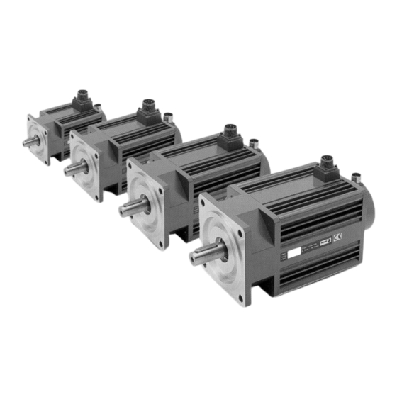
3-phase servomotors. FXM Outside appearance The following figure shows the outside shape of these servomotors and the location of the connectors for power supply, motor feedback, holding brake and fan (when having all these options). F- 2/2 Servomotor FXM. A. Without FAN. B. With FAN. 1. -
Page 39: Technical Data
3-phase servomotors. FXM Technical data Non-ventilated FXM with “A” winding · 400 Vac · All the data supplied here are for winding over-temperature of T=100 K with a room temperature of 40°C/104°F. The power cable shown in the table corresponds to servomotors without holding brake. T- 2/3 Non-ventilated FXM servomotors with “A”... - Page 40 3-phase servomotors. FXM T- 2/3 Non-ventilated FXM servomotors with “A” winding and wihout holding brake. Technical data. SERVOMOTOR Pcal Power terminal strip Power cable model SERVOMOTOR SERVOMOTOR* 1/min N·m N·m Type Nr of wires x mm² 4000 1.11 11.40A..00 MC 23 MPC-4x1.5-M...
-
Page 41: Ventilated Fxm With "A" Winding · 400 Vac
3-phase servomotors. FXM Ventilated FXM with “A” winding · 400 Vac · All the data supplied here are for winding over-temperature of T=100 K with a room temperature of 40°C/104°F. The power cable shown in the table corresponds to servomotors without holding brake. T- 2/4 Ventilated FXM servomotors with “A”... -
Page 42: Non-Ventilated Fxm With "F" Winding · 220 Vac
3-phase servomotors. FXM Non-ventilated FXM with “F” winding · 220 Vac · All the data supplied here are for winding over-temperature of T=100 K with a room temperature of 40°C/104°F. T- 2/5 Non-ventilated FXM servomotors with “F” winding and without holding brake. Technical data. SERVOMOTOR Pcal Power terminal strip... -
Page 43: Options / Expansions
3-phase servomotors. FXM Options / Expansions Holding brake FXM servomotors offer an optional holding brake that applies friction on to the shaft. IMPORTANT. Before installing a servomotor with a holding brake on the machine, carefully read all the warnings referring to the servomotor holding brake detailed in section 3 Storage and 5 Installation in the chapter on GENERAL PRECAUTIONS of this manual. -
Page 44: Connections
MC 23, MC 46 and MC 80 or angled AMC 23 and AMC 46. NOTE. FAGOR supplies these terminal strips separately (not with the servomotor) and upon request. - Page 45 3-phase servomotors. FXM Power connection The power connection between the servomotor and the drive will be made using the power cable as shown in the diagram: Power connector Brakeless FXM servomotors MC 23, AMC 23 MC 46, AMC 46 DRIVE Chassis Shield...
- Page 46 3-phase servomotors. FXM Note. Note that for servomotors with an MC-80 plug, the pin names are different: U phase (pin C), V phase (pin H), W phase (pin G) and PE (pin B). When using a brake, pin A will be supplied with 24 Vdc and pin E with 0 Vdc.
- Page 47 1. GENERAL CONCEPTS of this manual. To transmit the feedback signals from the motor feedback device to the drive, use (as appropriate) one of the following cables with FAGOR connectors. FXM|FKM SERVOMOTOR Ref.2105...
- Page 48 Using the EEC-SP- cable as motor feedback cable ensures compliance with Directive 2014/30/EU on Electromagnetic Compatibility. FAGOR supplies the EEC-SP- feedback cable upon request. If you use to manufacture you own cable, read the following instructions carefully to understand the diagrams correctly. Observe that there are two cables indicated as type I and type II.
- Page 49 3-phase servomotors. FXM Incremental TTL encoder. IECD- cable FAGOR supplies the IECD- feedback cable upon request. If you use to manufacture you own cable, read the following instructions carefully to understand the diagrams correctly. INFORMATION. Please note that the letters must be interpreted as positions when looking at the front of the unit.
-
Page 50: Sales Reference
3-phase servomotors. FXM Sales reference The sales reference of each servomotor is made up of letters and digits that mean the following: Note. Encoders with references: - I0, are only available on servomotors with winding F (220 Vac) - E1/A1, are only available on servomotors with winding A (400 Vac) F- 2/14 FXM servomotors. -
Page 51: Technical Data. Torque-Speed Curves
A winding (400 Vac) and F winding (220 Vac). Here are also the tables associating the servomotor model with the FAGOR drives that can govern it. Bear in mind that selecting the drive to govern a particular servomotor depends on the requirements of the application;... -
Page 52: Non-Ventilated Fxm With "A" · 400 Vac
3-phase servomotors. FXM Non-ventilated FXM with “A” · 400 Vac · FXM11 models T- 2/8 FXM11.A..0. Technical data. Model FXM11.A..0 Terminology Notation Units N·m Stall torque Rated torque N·m N·m Stall peak torque 1/min 2000 3000 4000 Rated speed 0.45 0.67 0.90... - Page 53 3-phase servomotors. FXM FXM12 models T- 2/10 FXM12.A..0. Technical data. Model FXM12.A..0 Terminology Notation Units Stall torque N·m Rated torque N·m Stall peak torque N·m Rated speed 1/min 2000 3000 4000 Stall current 0.86 1.29 1.72 Peak current Calculation power Pcal Rated power...
- Page 54 3-phase servomotors. FXM FXM13 models T- 2/12 FXM13.A..0. Technical data. Model FXM13.A..0 Terminology Notation Units Stall torque N·m Rated torque N·m Stall peak torque N·m Rated speed 1/min 2000 3000 4000 Stall current 1.23 1.85 2.50 Peak current 12.0 Calculation power Pcal...
- Page 55 3-phase servomotors. FXM FXM14 models T- 2/14 FXM14.A..0. Technical data. Model FXM14.A..0 Terminology Notation Units Stall torque N·m Rated torque N·m Stall peak torque N·m Rated speed 1/min 2000 3000 4000 Stall current Peak current 11.2 15.0 Calculation power Pcal Rated power Torque constant...
- Page 56 3-phase servomotors. FXM FXM31 models T- 2/16 FXM31.A..0. Technical data. Model FXM31.A..0 Terminology Notation Units N·m Stall torque N·m Rated torque Stall peak torque N·m Rated speed 1/min 2000 3000 4000 Stall current 0.97 1.45 1.92 Peak current Calculation power Pcal Rated power...
- Page 57 3-phase servomotors. FXM FXM32 models T- 2/18 FXM32.A..0. Technical data. Model FXM32.A..0 Terminology Notation Units N·m Stall torque N·m Rated torque Stall peak torque N·m Rated speed 1/min 2000 3000 4000 Stall current 1.89 2.80 3.80 Peak current 14.0 18.5 Calculation power...
- Page 58 3-phase servomotors. FXM FXM33 models T- 2/20 FXM33.A..0. Technical data. Model FXM33.A..0 Terminology Notation Units N·m Stall torque Rated torque N·m Stall peak torque N·m Rated speed 1/min 2000 3000 4000 Stall current Peak current 13.4 20.0 27.0 Calculation power Pcal Rated power...
- Page 59 3-phase servomotors. FXM FXM34 models T- 2/22 FXM34.A..0. Technical data. Model FXM34.A..0 Terminology Notation Units N·m Stall torque Rated torque N·m Stall peak torque N·m Rated speed 1/min 2000 3000 4000 Stall current Peak current Calculation power Pcal Rated power Torque constant N·m/A...
- Page 60 3-phase servomotors. FXM FXM53 models T- 2/24 FXM53.A..0. Technical data. Model FXM53.A..0 Terminology Notation Units Stall torque N·m 11.9 11.9 11.9 11.9 Rated torque N·m 11.1 10.5 Stall peak torque N·m Rated speed 1/min 1200 2000 3000 4000 Stall current Peak current Calculation power...
- Page 61 3-phase servomotors. FXM FXM54 models T- 2/26 FXM54.A..0. Technical data. Model FXM54.A..0 Terminology Notation Units Stall torque N·m 14.8 14.8 14.8 14.8 Rated torque 13.7 12.8 11.6 10.2 N·m Stall peak torque N·m Rated speed 1/min 1200 2000 3000 4000 Stall current 11.8 Peak current...
- Page 62 3-phase servomotors. FXM FXM55 models T- 2/28 FXM55.A..0. Technical data. Model FXM55.A..0 Terminology Notation Units Stall torque 17.3 17.3 17.3 17.3 N·m Rated torque 15.7 14.7 13.1 11.2 N·m Stall peak torque N·m Rated speed 1/min 1200 2000 3000 4000 Stall current 10.3 14.1...
- Page 63 3-phase servomotors. FXM FXM73 models T- 2/30 FXM73.A..0. Technical data. Model FXM73.A..0 Terminology Notation Units Stall torque 20,8 20,8 20,8 20,8 N·m Rated torque 19.2 17.7 15.2 11.9 N·m Stall peak torque N·m Rated speed 1/min 1200 2000 3000 4000 Stall current 12.3 16.5...
- Page 64 3-phase servomotors. FXM FXM74 models T- 2/32 FXM74.A..0. Technical data. Model FXM74.A..0 Terminology Notation Units Stall torque 27.3 27.3 27.3 27.3 N·m Rated torque 24.9 22.8 19.4 15.0 N·m Stall peak torque N·m Rated speed 1/min 1200 2000 3000 4000 Stall current 11.1 16.2...
- Page 65 3-phase servomotors. FXM FXM75 models T- 2/34 FXM75.A..0. Technical data. Model FXM75. A. . 0 Terminology Notation Units Stall torque N·m 33.6 33.6 33.6 33.6 Rated torque N·m 30.2 27.5 23.2 17.6 Stall peak torque N·m Rated speed 1/min...
- Page 66 3-phase servomotors. FXM FXM76 models T- 2/36 FXM76.A..0. Technical data. Model FXM76. A. . 0 Terminology Notation Units Stall torque 39.7 39.7 39.7 39.7 N·m Rated torque 35.3 31.9 26.6 19.8 N·m Stall peak torque N·m Rated speed 1/min...
- Page 67 3-phase servomotors. FXM FXM77 models T- 2/38 FXM77.A..0. Technical data. Model FXM77. A. . 0 Terminology Notation Units Stall torque 45.6 45.6 45.6 45.6 N·m Rated torque 40.0 36.0 29.6 21.7 N·m Stall peak torque N·m Rated speed 1/min...
- Page 68 3-phase servomotors. FXM FXM78 models T- 2/40 FXM78.A..0. Technical data. Model FXM78. A. . 0 Terminology Notation Units Stall torque 51.1 51.1 51.1 51.1 N·m Rated torque 44.3 39.6 32.2 23.0 N·m Stall peak torque N·m Rated speed 1/min...
-
Page 69: Ventilated Fxm With "A" Winding · 400 Vac
3-phase servomotors. FXM Ventilated FXM with “A” winding · 400 Vac · FXM53 models T- 2/42 FXM53.A..1. Technical data. Model FXM53. A. . 1 Terminology Notation Units Stall torque 17.8 17.8 17.8 17.8 N·m Rated torque N·m 17.0 16.4... - Page 70 3-phase servomotors. FXM FXM54 models T- 2/44 FXM54.A..1. Technical data. Model FXM54. A. . 1 Terminology Notation Units Stall torque 22.2 22.2 22.2 22.2 N·m Rated torque N·m 21.0 20.2 19.0 17.6 Stall peak torque N·m Rated speed 1/min...
- Page 71 3-phase servomotors. FXM FXM55 models T- 2/46 FXM55.A..1. Technical data. Model FXM55. A. . 1 Terminology Notation Units Stall torque N·m 25.9 25.9 25.9 25.9 Rated torque N·m 24.5 23.2 21.8 19.9 Stall peak torque N·m Rated speed 1/min...
- Page 72 3-phase servomotors. FXM FXM73 models T- 2/48 FXM73.A..1. Technical data. Model FXM73. A. . 1 Terminology Notation Units Stall torque N·m 31.2 31.2 31.2 31.2 Rated torque N·m 29.5 28.1 25.6 22.4 Stall peak torque N·m Rated speed 1/min...
- Page 73 3-phase servomotors. FXM FXM74 models T- 2/50 FXM74.A..1. Technical data. Model FXM74. A. . 1 Terminology Notation Units Stall torque N·m 40.9 40.9 40.9 40.9 Rated torque N·m 38.5 36.4 33.0 28.6 Stall peak torque N·m Rated speed 1/min...
- Page 74 3-phase servomotors. FXM FXM75 models T- 2/52 FXM75.A..1. Technical data. Model FXM75. A. . 1 Terminology Notation Units Stall torque N·m 50.4 50.4 50.4 50.4 Rated torque N·m 47.0 44.3 40.0 34.4 Stall peak torque N·m Rated speed 1/min...
- Page 75 3-phase servomotors. FXM FXM76 models T- 2/54 FXM76.A..1. Technical data. Model FXM76. A. . 1 Terminology Notation Units Stall torque N·m 59.5 59.5 59.5 59.5 Rated torque N·m 55.0 51.8 46.4 39.7 Stall peak torque N·m Rated speed 1/min...
- Page 76 3-phase servomotors. FXM FXM77 models T- 2/56 FXM77.A..1. Technical data. Model FXM77. A. . 1 Terminology Notation Units Stall torque N·m 68.4 68.4 68.4 68.4 Rated torque N·m 62.8 58.8 52.4 44.5 Stall peak torque N·m Rated speed 1/min...
- Page 77 3-phase servomotors. FXM FXM78 models T- 2/58 FXM78.A..1. Technical data. Model FXM78. A. . 1 Terminology Notation Units Stall torque N·m 76.6 76.6 76.6 76.6 Rated torque N·m 69.8 65.1 57.7 48.5 Stall peak torque N·m Rated speed 1/min...
-
Page 78: Non-Ventilated Fxm With "F" Winding · 220 Vac
3-phase servomotors. FXM Non-ventilated FXM with “F” winding · 220 Vac · FXM11 models T- 2/60 FXM11.F..0. Technical data. Model FXM11. F. . 0 Terminology Notation Units Stall torque N·m Rated torque N·m Stall peak torque N·m Rated speed 1/min... - Page 79 3-phase servomotors. FXM FXM12 models T- 2/61 FXM12.F..0. Technical data. Model FXM12. F. . 0 Terminology Notation Units Stall torque N·m Rated torque N·m Stall peak torque N·m Rated speed 1/min 4000 Stall current Peak current 19.3 Calculation power Pcal...
- Page 80 3-phase servomotors. FXM FXM13 models T- 2/62 FXM13.F..0. Technical data. Model FXM13. F. . 0 Terminology Notation Units Stall torque N·m Rated torque N·m Stall peak torque N·m Rated speed 1/min 4000 Stall current Peak current Calculation power Pcal Rated power...
- Page 81 3-phase servomotors. FXM FXM14 models T- 2/63 FXM14.F..0. Technical data. Model FXM14. F. . 0 Terminology Notation Units Stall torque N·m Rated torque N·m Stall peak torque N·m Rated speed 1/min 2000 4000 Stall current Peak current 17.2 Calculation power...
- Page 82 3-phase servomotors. FXM FXM31 models T- 2/64 FXM31.F..0. Technical data. Model FXM31. F. . 0 Terminology Notation Units Stall torque N·m Rated torque N·m Stall peak torque N·m Rated speed 1/min 2000 4000 Stall current Peak current Calculation power Pcal...
- Page 83 3-phase servomotors. FXM FXM32 models T- 2/65 FXM32.F..0. Technical data. Model FXM32. F. . 0 Terminology Notation Units Stall torque N·m Rated torque N·m Stall peak torque N·m Rated speed 1/min 2000 4000 Stall current Peak current Calculation power Pcal...
- Page 84 3-phase servomotors. FXM FXM33 models T- 2/66 FXM33.F..0. Technical data. Model FXM33. F. . 0 Terminology Notation Units Stall torque N·m Rated torque N·m Stall peak torque N·m Rated speed 1/min 2000 4000 Stall current Peak current Calculation power Pcal...
- Page 85 3-phase servomotors. FXM FXM34 models T- 2/67 FXM34.F..0. Technical data. Model FXM34. F. . 0 Terminology Notation Units Stall torque N·m Rated torque N·m Stall peak torque N·m Rated speed 1/min 2000 4000 Stall current 15.3 Peak current Calculation power...
- Page 86 3-phase servomotors. FXM FXM53 models T- 2/68 FXM53.F..0. Technical data. Model FXM53. F. . 0 Terminology Notation Units Stall torque N·m 11.9 11.9 11.9 Rated torque N·m 10.5 Stall peak torque N·m Rated speed 1/min 2000 3000 4000 Stall current 14.8...
- Page 87 3-phase servomotors. FXM FXM54 models T- 2/69 FXM54.F..0. Technical data. Model FXM54. F. . 0 Terminology Notation Units Stall torque N·m 14.8 14.8 Rated torque N·m 12.8 11.6 Stall peak torque N·m Rated speed 1/min 2000 3000 Stall current 12.7...
- Page 88 3-phase servomotors. FXM FXM55 models T- 2/70 FXM55.F..0. Technical data. Model FXM55. F. . 0 Terminology Notation Units Stall torque N·m 17.3 17.3 Rated torque N·m 15.8 14.7 Stall peak torque N·m Rated speed 1/min 1200 2000 Stall current 15.5...
- Page 89 3-phase servomotors. FXM FXM73 models T- 2/71 FXM73.F..0. Technical data. Model FXM73. F. . 0 Terminology Notation Units Stall torque N·m 20.8 Rated torque N·m 18.9 Stall peak torque N·m Rated speed 1/min 1200 Stall current 10.7 Peak current Calculation power...
- Page 90 3-phase servomotors. FXM FXM74 models T- 2/72 FXM74.F..0. Technical data. Model FXM74. F. . 0 Terminology Notation Units Stall torque N·m 27.3 Rated torque N·m 24.9 Stall peak torque N·m Rated speed 1/min 1200 Stall current 13.5 Peak current Calculation power...
- Page 91 Mass (with brake) 40.1 * Note that although this servomotor can provide a stall torque of 33.6 N·m, the largest FAGOR drive that can govern it can only get 29.5 N·m out of it. Note. These servomotors with “F” winding (220 Vac) can only be controlled by ACSD-L or MCS-L series drives.
-
Page 92: Axial And Radial Loads On The Shaft Extension
3-phase servomotors. FXM 2.10 Axial and radial loads on the shaft extension The following table shows the maximum axial and radial forces that the shaft extension can withstand: T- 2/74 Maximum values for axial and radial loads. Series Axial force Radial force Distance... -
Page 93: Dimensions
1 in = 25.4 mm F- 2/55 Synchronous motors. FXM1 series. Dimensions. Dimension ØD j6 Units FXM1 0.55 Dimension Units FXM1 0.19 0.19 0.78 0.62 M5x12.5 F- 2/56 Synchronous motors. FXM1 series. Dimensions of the shaft extension. FXM|FKM SERVOMOTOR Ref.2105 · 93 ·... -
Page 94: Fxm3 Series
3-phase servomotors. FXM FXM3 series ±0.1 ±0.1 Dimension Units FXM31 5.98 FXM32 7.36 FXM33 8.74 Dimensions in mm FXM34 10.12 1 in = 25.4 mm F- 2/57 Synchronous motors. FXM3 series. Dimensions. Dimension ØD j6 Units FXM3 0.75... -
Page 95: Fxm5 Series
3-phase servomotors. FXM FXM5 series ±0.1 ±0.25 WITH BRAKE: LB+28 Dimension Units FXM53 9.33 Dimensions in mm FXM54 10.71 1 in = 25.4 mm FXM55 12.09 F- 2/59 Synchronous servomotors. FXM5 series. Dimensions. Dimension ØD j6 Units FXM5 0.94... -
Page 96: Fxm7 Series
3-phase servomotors. FXM FXM7 series ±0.1 ±0.25 WITH BRAKE: LB+41 Dimension Dimension Units Units Io 23 A (MC 23) 1.57 35 1.38 229 9.01 FXM73 10.08 23 A < Io 46 A (MC 46) 50 1.96 40 1.57 236 9.29... -
Page 97: Fxm5/V Series
3-phase servomotors. FXM FXM5/V series ±0.1 ±0.25 WITH BRAKE: L+28 Dimension Dimension Units Units Io 23 A (MC 23) FXM53/V 365 14.37 40 1.57 154 6.06 23 A < Io 46 A (MC 46) FXM54/V 400 15.74 50 1.96 159 6.25... -
Page 98: Fxm7/V Series
3-phase servomotors. FXM FXM7/V series ±0.1 ±0.25 WITH BRAKE: L+41 Dimension Dimension Units Units FXM73/V 384 15.11 Io 23 A (MC 23) 1.57 157 6.18 FXM74/V 419 16.49 23 A < Io 46 A (MC 46) 1.96 162 6.25 FXM75/V 454 17.87... -
Page 99: 3-Phase Servomotors. Fkm
Description FAGOR FKM servomotors are synchronous AC brushless with permanent magnets. They are especially designed to be used with FAGOR drives. They are ideal for controlling feed and positioning axes in machine tool applications as well as handling systems, textile machinery, printers, robotics, etc. -
Page 100: General Characteristics
3-phase servomotors. FKM General characteristics FKM1 series T- 3/1 FKM1 servomotors. Standard characteristics. Excitation Permanent Neodymium magnets (Nd) Temperature sensor PTC 111-K13-140°C thermistor Shaft extensión Cylindrical without keyway. Option: with keyway Mounting methods IM B5, IM V1, IM V3 meets IEC 60034-7 Mechanical tolerances Normal class N, meets IEC 72/1971 Class N (class R optional) meets DIN 45665... -
Page 101: Fkm9 Series
3-phase servomotors. FKM FKM9 series T- 3/3 FKM9 servomotors. Standard characteristics. Excitation Permanent Neodymium magnets (Nd) Temperature sensor PTC KTY84-130 thermistor Shaft extension Cylindrical without keyway. Option: with keyway Mounting methods IM B5, IM V1, IM V3 meets IEC 60034-7 Mechanical tolerances Normal class N, meets IEC 72/1971 N class (class R optional) meets DIN 45665... -
Page 102: Temperature Sensors
WARNING. The temperature sensor KTY84-130 has polarity. If you wish to manufacture your own feedback cable, make sure that the polarity is correct. See the feedback cable diagrams later on. FAGOR supplies this cable upon request. FXM|FKM SERVOMOTOR DANGER. -
Page 103: Ptc 111-K13-140 Thermistor
3-phase servomotors. FKM PTC 111-K13-140 thermistor The FKM1 servomotor series has a PTC 111-K13-140 thermistor for the thermal protection of the servomotor winding. This is the positive temperature coefficient (PTC) and has no polarity. T- 3/5 Characteristics of the temperature sensor PTC 111-K13-140°C. Sensor type PTC 111-K13-140 thermistor Sensor connection... -
Page 104: Rtd Pt1000 Thermoresistance
3-phase servomotors. FKM RTD Pt1000 thermoresistance The servomotors in the FKM family ·except for the FKM1/9 series· have a platinum R esistance T emperature D etector Pt1000·(Ro = 1000 ohms at 0°C), providing thermal protection for the servomotor. Provides great linearity, speed and a temperature range between -200°C/-328°F and +850°C/1562°F. -
Page 105: Outside Appearance
3-phase servomotors. FKM Outside appearance The figure shows the outside shape of these servomotors and the location of the connectors for power supply, motor feedback, holding brake (if applicable) and for the fan (if applicable): FKM1 FKM9 FKM2 FKM4 FKM6 FKM6/V... -
Page 106: Rotary Connectors
3-phase servomotors. FKM Rotary connectors WARNING. Do not remove the locking screws of any connector. FKM1 series In the FKM1 series, the power connector and the feedback connector are built into the end of the cables leaving through the gland from the servomotor itself. -
Page 107: Fkm6/V Series
3-phase servomotors. FKM FKM6/V series In the FKM6/V series · on FKM66.A.. 1 . models · the power connectors and those of the fan may be rotated, making it easier to connect the cable when the installation conditions so require. However, this is not the case with the feedback signal connector, which must be kept fixed in the indicated position: N o t e . -
Page 108: Fkm8/V Series
3-phase servomotors. FKM FKM8/V series On the FKM8/V series, the power connectors and those of the fan may be rotated making it easier to connect the cable when the installation conditions so require. But not so the feedback signal connector that must be kept fixed in the indicated position: Note. -
Page 109: Technical Data
3-phase servomotors. FKM Technical data All the data supplied here are for winding over-temperature of T=100 K with a room temperature of 40°C/104°F. The power cable shown in the table corresponds to servomotors without holding brake. Non-ventilated FKM with “A” winding · 400 Vac · T- 3/7 Technical data of non-ventilated FKM servomotors with “A”... -
Page 110: Ventilated Fkm With "A" Winding · 400 Vac
3-phase servomotors. FKM Ventilated FKM with “A” winding · 400 Vac · T- 3/8 Technical data of ventilated FKM servomotors with “A” winding and without brake. Servomotor model Pcal POWER POWER POWER terminal cable of the terminal strip of the MOTOR* strip of the MOTOR... -
Page 111: Options / Expansions
3-phase servomotors. FKM Options / expansions Holding brake FKM servomotors offer an optional holding brake that applies friction on to the shaft. IMPORTANT. Before installing a servomotor with a holding brake on the machine, carefully read all the warnings referring to the servomotor holding brake detailed in section 3 Storage and 5 Installation in the chapter on GENERAL PRECAUTIONS of this manual. -
Page 112: Fan
3-phase servomotors. FKM Optionally: FKM6 series · only on FKM66.A..1. models · T- 3/11 Technical data of the fan. Rated voltage: 24 Vdc. SERVO Voltage Ambient Power Flow Noise Speed MOTOR temperature input emission min./max. series Units °C m³/h dB(A) -
Page 113: Connections
FKM66. 30A..21. is equipped with the MC-30/6 connector. Note. For the servomotors of these series, FAGOR supplies (on request) the MC-20/6 and MC-30/6 female connectors (disassembled) in a plastic bag together with six terminals. Prior to connection, the user must create a power cable by mounting this connector on a 4-wire MPC- 4x-M cable (if the motor does not have a brake) or 6-wire MPC-... - Page 114 3-phase servomotors. FKM Use a screwdriver to separate piece 5 into two pieces 5a and 5b. Insert the wires and the whole length of the stripped shield through the holes of the two pieces leaving the shield between them as shown in figure F- 3/11 .
- Page 115 3-phase servomotors. FKM SF-Z0026 CONTACT TYPE Ø mm CROSS TOTAL CONDUCTOR STRIPPING SETTING PARAMETERS SOCKET SECTION LENGTH INSERT Ø LENGTH LOCATOR CRIMPING ARBOR mm² SETTING mm SM-36KS002 2.50 36.95 2.00 SM-36KS002 4.00 36.95 2.10 SM-36KS003 4.00 36.95 2.20 SM-36KS003 6.00 36.95...
- Page 116 Remember that before connecting the power cable, it must be assembled. Ref.2105 FAGOR supplies, upon request and in meters, the MPC-4x+(2x)-M cable and the MC-20/6 or MC-30/6 connector, also upon request, that must be assembled to it. Proceed as described earlier. See figure F- 3/9 Once the power cable is put together, proceed with the connection.
- Page 117 3-phase servomotors. FKM Servomotor power connection The power connection between the servomotor and the drive will be made using the MPC power cable as shown in the diagram: Brakeless FKM1/2/4/6/6V servomotors | MC-30/6 FKM1/2/4/6/6V servomotors, with holding brake | MC-30/6 F- 3/19 Power connection diagram between an FKM1/2/4/6/6V servomotor and a...
- Page 118 3-phase servomotors. FKM Holding brake connection To govern the optional holding brake of FKM1/2/4/6 series axis servomotors they must be supplied with 24 Vdc. The power consumed by them and their main characteristics have already been described in the T- 3/10 table. WARNING.
- Page 119 1. Ref.2105 GENERAL CONCEPTS of this manual. To transmit the feedback signals from the motor feedback device to the drive, use (as appropriate) one of the following cables with FAGOR connectors. · 119 ·...
- Page 120 Using the EEC-SP- cable as feedback cable ensures compliance with the European Directive 2014/30/EU on Electromagnetic Compatibility. FAGOR supplies the EEC-SP- feedback cable upon request. If you use to manufacture you own cable, read the following instructions carefully to understand the diagrams correctly. Observe that there are two cables indicated as type I and type II.
- Page 121 3-phase servomotors. FKM Incremental TTL encoder. IECD- cable FAGOR supplies the IECD- feedback cable upon request. If you use to manufacture you own cable, read the following instructions carefully to understand the diagrams correctly. INFORMATION. Please note that the letters must be interpreted as positions when looking at the front of the unit.
- Page 122 Remember that before connecting the fan power cable, it must be assembled. Get a 2x1.5+G section cable and mount · According to servomotor model · the MC-20/6 or MC-30/6 connector supplied by FAGOR upon request. Proceed following assembling instructions. See figure F- 3/9 and followings.
-
Page 123: Fkm8/8V/9 Series
4-wire cable MPC-4x-M (if the servomotor does not have a brake) or a 6-wire cable MPC-4x+(2x)-M (if the servomotor has a brake). These cables are also supplied by FAGOR (upon request) in meters. Once the power cable has been assembled, it is connected by screwing the female connector MC-61/6 of the power cable into the power base connector of the servomotor. - Page 124 Remember that before connecting the power cable, it must be assembled. SERVOMOTOR FAGOR supplies, upon request and in meters, the MPC-4x+(2x)-M cable and the MC-61/6 connector, also upon request, that must be assembled to it. Proceed as described earlier. See figure F- 3/25 Ref.2105...
- Page 125 3-phase servomotors. FKM Servomotor power connection The power connection between the servomotor and the drive will be made using the MPC-4x... power cable as shown in the diagrams: Brakeless FKM8/8V/9 servomotors FKM8/8V/9 servomotors with holding brake F- 3/27 Power connection diagram between an FKM8/8V/9 servomotor and a drive.
- Page 126 3-phase servomotors. FKM Holding brake connection Governing the holding brake optionally carried by axis servomotor models FKM8 (all models), FKM8/V as well as FKM94 and FKM95 models r e q u ir e s 24 Vd c . h e p o w e r c o n s u m ed b y t h em a n d t h e i r m a i n characteristics have already been described in the T- 3/10 table.
- Page 127 Remove the top lid of the servomotor to get to it. FXM|FKM SERVOMOTOR To take the feedback signals from the servomotor feedback device to the drive, use one of the following cables with connectors supplied by FAGOR. Ref.2105 · 127 ·...
- Page 128 Using the EEC-SP- cable as feedback cable ensures compliance with the European Directive 2014/30/EU on Electromagnetic Compatibility. FAGOR supplies the EEC-SP- feedback cable upon request. If you use to manufacture you own cable, read the following instructions carefully to understand the diagrams correctly. Observe that there are two cables indicated as type I and type II.
- Page 129 MANDATORY. Remember that before connecting the fan power cable, it must be assembled. Get a 2x1.5+G section cable and mount the MC-20/6 connector supplied by FAGOR upon request. Proceed following the MC- 20/6 connector assembling instructions See figure F- 3/9 and followings.
-
Page 130: Sales Reference
3-phase servomotors. FKM Sales reference The sales reference of each servomotor is made up of letters and digits that mean the following: Note. The encoders with reference: - I0, only available on FKM2/4/6 series. - E3/A3, only available on FKM2/4/6/8/9 series. - E4/A4, only available on FKM1 series. -
Page 131: Technical Data. Torque-Speed Curves
A winding (400 Vac) and F winding (220 Vac). Here are also the tables associating the servomotor model with the FAGOR drives that can govern it. Bear in mind that selecting the drive to govern a particular servomotor depends on the requirements of the application;... -
Page 132: Non-Ventilated Fkm With "A" Winding · 400 Vac
3-phase servomotors. FKM Non-ventilated FKM with “A” winding · 400 Vac · FKM12 models T- 3/13 FKM12.A..0.02. Technical data. Model FKM12.A..0.02 Terminology Notation Units Stall torque N·m 0.54 Rated torque N·m 0.48 Stall peak torque N·m 2.20 Rated speed 1/min 4500 Stall current... - Page 133 3-phase servomotors. FKM FKM14 models T- 3/15 FKM14.A..0.02. Technical data. Model FKM14.A..0.02 Terminology Notation Units 0.95 Stall torque N·m 0.85 Rated torque N·m Stall peak torque N·m Rated speed 1/min 4500 1.15 Stall current 1.07 Rated current Peak current Calculation power Pcal 0.45...
- Page 134 3-phase servomotors. FKM FKM21 models T- 3/17 FKM21.A..0.. Technical data. Model FKM21.A..0. Terminology Notation Units N·m Stall torque N·m 0.824 Rated torque Stall peak torque N·m Rated speed 1/min 6000 Stall current Peak current 11.0 Calculation power Pcal Rated power Torque constant N·m/A...
- Page 135 3-phase servomotors. FKM FKM22 models T- 3/19 FKM22.A..0.. Technical data. Model FKM22.A..0. Terminology Notation Units N·m Stall torque N·m 2.56 1.92 1.55 Rated torque Stall peak torque N·m Rated speed 1/min 3000 5000 6000 Stall current Peak current 10.0 16.0 18.0...
- Page 136 3-phase servomotors. FKM FKM42 models T- 3/21 FKM42.A..0.. Technical data. Model FKM42.A..0. Terminology Notation Units Stall torque N·m Rated torque N·m 4.60 3.34 1.89 Stall peak torque N·m Rated speed 1/min 3000 4500 6000 Stall current Peak current 19.0 28.0 34.0...
- Page 137 3-phase servomotors. FKM FKM43 models T- 3/23 FKM43.A..0.. Technical data. Model FKM43.A..0. Terminology Notation Units Stall torque N·m Rated torque N·m Stall peak torque N·m Rated speed 1/min 2000 3000 4000 Stall current Peak current 14.4 21.8 32.7 Calculation power Pcal 1.88...
- Page 138 3-phase servomotors. FKM FKM44 models T- 3/25 FKM44.A..0.. Technical data. Model FKM44.A..0. Terminology Notation Units 30...-2 Stall torque N·m 11.6 11.6 11.6 11.6 Rated torque N·m Stall peak torque N·m Rated speed 1/min 2000 3000 3000 4000 Stall current 10.7 Peak current 19.0...
- Page 139 3-phase servomotors. FKM FKM62 models T- 3/27 FKM62.A..0.. Technical data. Model FKM62.A..0. Terminology Notation Units Stall torque N·m Rated torque N·m Stall peak torque N·m Rated speed 1/min 3000 4000 6000 Stall current 13.1 Peak current 28.0 37.0 52.0 Calculation power Pcal...
- Page 140 3-phase servomotors. FKM FKM63 models T- 3/29 FKM63.A..0.. Technical data. Model FKM63.A..0. Terminology Notation Units Stall torque N·m 12.5 12.5 12.5 Rated torque N·m 11.0 Stall peak torque N·m Rated speed 1/min 2000 3000 4000 Stall current 12.3 Peak current 21.1 37.1...
- Page 141 3-phase servomotors. FKM FKM64 models T- 3/31 FKM64.A..0.. Technical data. Model FKM64.A..0. Terminology Notation Units Stall torque N·m 16.5 16.5 16.5 Rated torque N·m 13.6 11.2 Stall peak torque N·m Rated speed 1/min 2000 3000 4000 Stall current 12.1 16.2 Peak current...
- Page 142 3-phase servomotors. FKM FKM66 models T- 3/33 FKM66.A..0.. Technical data. Model FKM66.A..0. Terminology Notation Units 20...-2 Stall torque N·m 23.5 23.5 23.5 Rated torque N·m 16.7 16.7 12.2 Stall peak torque N·m 94.0 94.0 94.0 Rated speed 1/min 2000 2000 3000...
- Page 143 3-phase servomotors. FKM FKM82 models T- 3/35 FKM82.A..0.. Technical data. Model FKM82.A..0. Terminology Notation Units Stall torque N·m 32.0 32.0 32.0 Rated torque N·m 25.0 20.0 12.0 Stall peak torque N·m 96.0 96.0 96.0 Rated speed 1/min 2000 3000 4000 Stall current 13.2 19.8...
- Page 144 3-phase servomotors. FKM FKM83 models T- 3/37 FKM83.A..0.. Technical data. Model FKM83.A..0. Terminology Notation Units Stall torque N·m 41.0 41.0 Rated torque N·m 32.0 21.0 Stall peak torque N·m 123.0 123.0 Rated speed 1/min 2000 3000 Stall current 17.0 27.1 Peak current...
- Page 145 3-phase servomotors. FKM FKM84 models T- 3/39 FKM84.A..0.. Technical data. Model FKM84.A..0. Terminology Notation Units Stall torque N·m 52.0 52.0 Rated torque N·m 38.0 17.0 Stall peak torque N·m 156.0 156.0 Rated speed 1/min 2000 3000 Stall current 21.5 32.2 Peak current...
- Page 146 3-phase servomotors. FKM FKM85 models T- 3/41 FKM85.A..0.. Technical data. Model FKM85.A..0. Terminology Notation Units Stall torque N·m 74.0 Rated torque N·m 46.0 Stall peak torque N·m 222.0 Rated speed 1/min 2000 Stall current 29.3 Peak current 87.0 Calculation power Pcal 15.5...
- Page 147 3-phase servomotors. FKM FKM94 models T- 3/43 FKM94.A..0.0. Technical data. Model FKM94.A..0.0 Terminology Notation Units Stall torque N·m Rated torque N·m Stall peak torque N·m Rated speed 1/min 2000 Stall current 25.4 Peak current 99.0 Calculation power Pcal 14.2 Rated power 11.7...
- Page 148 3-phase servomotors. FKM FKM95 models T- 3/45 FKM95.A..0.0. Technical data. Model FKM95.A..0.0 Terminología Notation Units Stall torque N·m Rated torque N·m Stall peak torque N·m Rated speed 1/min 2000 Stall current 33.1 Peak current 129.0 Calculation power Pcal 19.5 Rated power 14.7...
- Page 149 3-phase servomotors. FKM FKM96 models T- 3/47 FKM96.A..0.0. Technical data. Model FKM96.A..00.0 Terminology Notation Units Stall torque N·m Rated torque N·m Stall peak torque N·m Rated speed 1/min 2000 Stall current 42.1 Peak current 164.0 Calculation power Pcal Rated power 17.8 Torque constant...
-
Page 150: Ventilated Fkm With "A" Winding · 400 Vac
3-phase servomotors. FKM Ventilated FKM with “A” winding · 400 Vac · FKM66 models T- 3/49 FKM66.A..1.. Technical data. Model FKM66.A..1. Terminology Notation Units 20...-2 Stall torque N·m 32.0 32.0 Rated torque N·m 27.0 23.5 Stall peak torque N·m 94.0 94.0... - Page 151 3-phase servomotors. FKM FKM82 models T- 3/51 FKM82.A..1.. Technical data. Model FKM82.A..1. Terminology Notation Units Stall torque N·m 40.0 Rated torque N·m 31.0 Stall peak torque N·m 96.0 Rated speed 1/min 4000 Stall current 33.0 Peak current 79.0 Calculation power Pcal 16.7...
- Page 152 3-phase servomotors. FKM FKM83 models T- 3/53 FKM83.A..1.. Technical data. Model FKM83.A..1. Terminology Notation Units Stall torque N·m 60.0 Rated torque N·m 45.0 Stall peak torque N·m 123.0 Rated speed 1/min 3000 Stall current 39.6 Peak current 81.0 Calculation power Pcal 18.8...
- Page 153 3-phase servomotors. FKM FKM84 models T- 3/55 FKM84.A..1.. Technical data. Model FKM84.A..1. Terminology Notation Units Stall torque N·m 80.0 80.0 Rated torque N·m 68.0 60.0 Stall peak torque N·m 156.0 156.0 Rated speed 1/min 2000 3000 Stall current 33.0 49.5 Peak current...
- Page 154 3-phase servomotors. FKM FKM85 models T- 3/57 FKM85.A..1.. Technical data. Model FKM85.A..1. Terminology Notation Units 100.0 91.0 Stall torque N·m Rated torque N·m 88.0 57.0 N·m Stall peak torque 222.0 222.0 1/min Rated speed 2000 3000 Stall current 39.6 60.0 Peak current...
-
Page 155: Non-Ventilated With "F" Winding · 220 Vac
3-phase servomotors. FKM Non-ventilated with “F” winding · 220 Vac · FKM21 models T- 3/59 FKM21.F..0.. Technical data. Model FKM21.F..0. Terminology Notation Units Stall torque N·m Rated torque N·m Stall peak torque N·m Rated speed 1/min 6000 Stall current Peak current Calculation power Pcal... - Page 156 3-phase servomotors. FKM FKM22 models T- 3/60 FKM22.F..0.. Technical data. Model FKM22.F..0. Terminology Notation Units Stall torque N·m Rated torque N·m Stall peak torque N·m Rated speed 1/min 3000 5000 Stall current Peak current Calculation power Pcal Rated power Torque constant N·m/A Acceleration time...
- Page 157 3-phase servomotors. FKM FKM42 models T- 3/61 FKM42.F..0.. Technical data. Model FKM42.F..0. Terminology Notation Units Stall torque N·m Rated torque N·m Stall peak torque N·m Rated speed 1/min 3000 4500 Stall current 12.4 Peak current Calculation power Pcal Rated power Torque constant N·m/A...
- Page 158 3-phase servomotors. FKM FKM43 models T- 3/62 FKM43.F..0.. Technical data. Model FKM43.F..0. Terminology Notation Units Stall torque N·m Rated torque N·m Stall peak torque N·m Rated speed 1/min 3000 Stall current 13.8 Peak current 55.4 Calculation power Pcal Rated power Torque constant N·m/A...
- Page 159 3-phase servomotors. FKM FKM44 models T- 3/63 FKM44.F..0.. Technical data. Model FKM44.F..0. Terminology Notation Units Stall torque N·m 11.6 Rated torque N·m Stall peak torque N·m Rated speed 1/min 3000 Stall current 15.6 Peak current Calculation power Pcal Rated power Torque constant N·m/A...
- Page 160 3-phase servomotors. FKM FKM62 models T- 3/64 FKM62.F..0.. Technical data. Model FKM62.F..0. Terminology Notation Units Stall torque N·m Rated torque N·m Stall peak torque N·m Rated speed 1/min 3000 4000 Stall current 13.1 16.4 Peak current Calculation power Pcal Rated power Torque constant...
- Page 161 3-phase servomotors. FKM FKM63 models T- 3/65 FKM63.F..0.. Technical data. Model FKM63.F..0. Terminology Notation Units Stall torque N·m 12.5 12.5 Rated torque N·m 11.0 Stall peak torque N·m Rated speed 1/min 2000 3000 Stall current 11.7 16.6 Peak current 46.6 66.4 Calculation power...
- Page 162 3-phase servomotors. FKM FKM64 models T- 3/66 FKM64.F..0.. Technical data. Model FKM64.F..0. Terminology Notation Units Stall torque N·m 16.5 16.5 Rated torque N·m 13.6 11.2 Stall peak torque N·m Rated speed 1/min 2000 3000 Stall current 14.3 20.0 Peak current Calculation power Pcal...
- Page 163 3-phase servomotors. FKM FKM66 models T- 3/67 FKM66.F..0.. Technical data. Model FKM66.F..0. Terminology Notation Units Stall torque N·m 23.5 Rated torque N·m 16.7 Stall peak torque N·m Rated speed 1/min 2000 Stall current 19.2 Peak current 76.8 Calculation power Pcal Rated power Torque constant...
-
Page 164: Axial And Radial Loads On The Shaft Extension
3-phase servomotors. FKM 3.11 Axial and radial loads on the shaft extension The following table shows the maximum axial and radial forces that the shaft extension can withstand: T- 3/68 Maximum values for axial and radial loads. Series Axial force Radial force Distance... -
Page 165: Dimensions
3-phase servomotors. FKM 3.12 Dimensions FKM1 series Dimensions in mm 50.6 1 in = 25.4 mm CABLE LENGTH 1.0 m 4x R2.9 1000 Dimension without brake with standard brake Motor Units FKM12 4.29 5.78 FKM14 5.47 6.96 F- 3/65 Synchronous servomotors. - Page 166 3-phase servomotors. FKM FKM2 series Dimensions in mm 1 in = 25.4 mm ±0.1 ±0.1 R3.5 with standard brake / without brake Dimension Units FKM21 4.17 8.19 FKM22 5.11 9.13 ØD j6 Dimension Units FKM2 0.74 0.23 0.23 1.18 21.5 0.84 M6x16 F- 3/66...
- Page 167 3-phase servomotors. FKM FKM4 series Dimensions in mm 1 in = 25.4 mm ±0.1 ±0.1 R4.5 with standard brake / without brake Dimension Units FKM42 5.23 9.72 FKM43 6.88 11.38 FKM44 6.88 11.38 ØD j6 Dimension Units 0.94 0.31 0.27...
-
Page 168: Fkm6 Series
3-phase servomotors. FKM FKM6 series Dimensions in mm 1 in = 25.4 mm ±0.25 ±0.1 with standard brake / without brake Dimension Units FKM62 5.35 10.24 FKM63 6.77 11.65 FKM64 6.77 11.65 FKM66 8.18 13.07 ØD k6 Dimension Units FKM6 0.39... -
Page 169: Fkm6/V Series
3-phase servomotors. FKM FKM6/V series Dimensions in mm Models without brake 1 in = 25.4 mm FKM66.20A..01.2 ±0.1 ±0.1 ±0.25 233.5 325.5 383.5 Models with extra-torque brake Dimensions in mm 1 in = 25.4 mm FKM66.20A..21.2 FKM66.30A..21. ±0.1 ±0.1 ±0.25... -
Page 170: Ref.2105 Fkm8 Series
3-phase servomotors. FKM FKM8 series Dimensions in mm 1 in = 25.4 mm ±0.25 ±0.1 without brake with standard brake Dimension Units FKM82 246 9.68 388 15.27 296 11.65 438 17.24 FKM83 296 11.65 438 17.24 346 13.62 488 19.21 FKM84 346 13.62 488 19.21 396 15.59 538 21.18 FKM85... -
Page 171: Fkm8/V Series
3-phase servomotors. FKM FKM8/V series Dimensions in mm 1 in = 25.4 mm ±0.1 ±0.25 without brake with standard brake SERVOMOTOR Dimension Units FKM82/V 11.41 16.65 19.80 11.41 18.62 21.77 FKM83/V 11.41 18.62 21.77 11.41 20.59 23.74 FKM84/V 15.35 20.59 23.74... -
Page 172: Fkm9 Series
3-phase servomotors. FKM FKM9 series Dimensions in mm 1 in = 25.4 mm without brake with standard brake Dimension Units FKM94 3.14 527 20.7 392 15.4 621 24.4 486 19.1 FKM95 110 4.33 625 24.6 460 18.1 720 28.3 555 21.8 FKM96 110 4.33 693 27.3 528 20.8 The FKM96 model does not offer the brake option. - Page 174 FAGOR AUTOMATION Fagor Automation S. Coop. Bº San Andrés, 19 - Apdo. 144 E-20500 Arrasate-Mondragón, Spain Tel: +34 943 719 200 +34 943 039 800 Fax: +34 943 791 712 E-mail: info@fagorautomation.es www.fagorautomation.com...
Need help?
Do you have a question about the FXM1 Series and is the answer not in the manual?
Questions and answers