Table of Contents
Advertisement
Quick Links
A S S E M B L Y M A N U A L
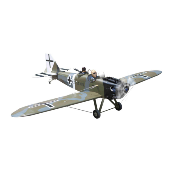
JUNKERS CL1 G-BUYU
Code: SEA275
" Graphics and specifications may change without notice " .
Specifications:
Wingspan---------------68.9 in (175 cm).
Wing area---------------776.6 sq.in ( 50.1 sq.dm).
Weight-------------------8.8 lbs (4.0 kg).
Length-------------------48.3 in (122.6 cm).
Engine-------------------10cc - 15cc.
Radio--------------------4 channels with 5 servos.
1
Advertisement
Table of Contents

Related Manuals for Seagull Models JUNKERS CL1 G-BUYU


Summary of Contents for Seagull Models JUNKERS CL1 G-BUYU
- Page 1 A S S E M B L Y M A N U A L JUNKERS CL1 G-BUYU Code: SEA275 “ Graphics and specifications may change without notice ” . Specifications: Wingspan---------------68.9 in (175 cm). Wing area---------------776.6 sq.in ( 50.1 sq.dm).
-
Page 2: Kit Contents
JUNKERS CL1 G-BUYU Instruction Manual. INTRODUCTION. Thank you for choosing the JUNKERS ARF by SG MODELS . The JUNKERS was de- signed with the intermediate/advanced sport flyer in mind. It is a semi scale airplane which is easy to fly and quick to assemble. The airframe is conventionally built using balsa, ply- wood to make it stronger than the average ARF, yet the design allows the aeroplane to be kept light. -
Page 3: Hinging The Aileron
KIT CONTENTS. HINGING THE AILERON. SEA275 JUNKERS CL1 G-BUYU Note : The control surfaces, including the ai- 1. Fuselage lerons, elevators, and rudder, are prehinged 2. Wing set with hinges installed, but the hinges are not 3. Tail set glued in place. It is imperative that you prop- 4. - Page 4 JUNKERS CL1 G-BUYU Instruction Manual. 4) Deflect the aileron and completely satu- 8) After both ailerons are securely hinged, rate each hinge with thin C/A glue. The ailer- firmly grasp the wing panel and aileron to ons front surface should lightly contact the make sure the hinges are securely glued and wing during this procedure.
-
Page 5: Installing The Aileron Servos
INSTALLING THE AILERON SERVOS. 3) Apply 2-3 drops of thin C/A to each of the mounting holes. Allow the C/A to cure without using accelerator. C/A glue 4) Use dental floss to secure the connec- Because the size of servos differ, you tion so they cannot become unplugged. - Page 6 JUNKERS CL1 G-BUYU Instruction Manual. C/A glue 7) Remove the string from the wing at the servo location and use the tape to attach it to the servo extension lead. Pull the lead through the wing and remove the string.
-
Page 7: Aileron Pushrod Installation
AILERON PUSHROD INSTALLATION. Please see below pictures. Nylon Snap keeper. Hex Nut. Fuel tubing. INSTALLING THE FUSELAGE SERVOS. Use a felt tip pen to mark the wire where Because the size of servos differ, you it crosses the hole. Use a pair of pliers to may need to adjust the size of the precut put a shrp 90-degree bend in the wire at opening in the mount. - Page 8 JUNKERS CL1 G-BUYU Instruction Manual. Loctite secure. Adjustable servo connector. Servo arm. Switch. Throttle servo arm. Rudder servo arm. INSTALLING THE ENGINE SWITCH. Elevator servo arm. Trim and cut. INSTALLING THE RECEIVER SWITCH. Install the switch into the precut hole in the side, in the fuselage.
- Page 9 1) The blind nuts for securing the land- ing gear are already mounted inside the fuselage. 2) Using the hardware provided, mount the main landing gear to the fuselage. 3) Place the fuselage inverted on the Collar. workbench in a suitable stand. Set the landing gear in place and use a screw- drive to secure the landing gear to the fu- selage using bolts M4x20mm and wash-...
-
Page 10: Installing Wheels
JUNKERS CL1 G-BUYU Instruction Manual. Collar. INSTALLING WHEELS. INSTALLING THE STOPPER ASSEMBLY. 1) Using a modeling knife, carefully cut off the rear portion of one of the 3 nylon tubes leaving 1/2” protruding from the rear of the stopper. This will be the fuel pick up tube. -
Page 11: Fuel Tank Installation
FUEL TANK INSTALLATION. You should mark which tube is the vent and which is the fuel pickup when you attach fuel tubing to the tubes in the stopper. Once the Plywood template tank is installed inside the fuselage, it may be - If you use Gasoline engine, you will glue it difficult to determine which is which. -
Page 12: Engine Mount Installation
JUNKERS CL1 G-BUYU Instruction Manual. Blow through one of the lines to ensure the fuel lines have not become kinked inside the fuel tank compartment. Air should flow through easily. ENGINE MOUNT INSTALLATION. 1) Locate the items necessary to install the engine mount included with your model. - Page 13 4) On the fire wall has the location for the throttle pushrod tube (pre-drill). 5) Slide the pushrod tube in the firewall and guide it through the fuel tank mount. Use medium C/A to glue the tube to the firewall and the fuel tank mount. 6) Connect the Z-bend in the 450mm throttle pushrod to the outer hole of the 143mm...
- Page 14 JUNKERS CL1 G-BUYU Instruction Manual. COWLING. Please see below pictures. 8) Reinstall the servo horn by sliding the connector over the pushrod wire. Cent- er the throttle stick and trim and install the servo horn perpendiular to the servo center line.
- Page 15 Because of the size of the cowl, it may be nec- 2) Install the muffler and muffler extension essary to use a needle valve extension for the onto the engine and make the cutout in the high speed needle valve. Make this out of suf- cowl for muffler clearance.
- Page 16 JUNKERS CL1 G-BUYU Instruction Manual. Blind nut. M3x15mm M4x20mm Epoxy 4) Attach the motor to the front of the electric motor box using four 4mm blind nut, four M3x15mm hex head bolts to se- cure the motor. Please see picture shown.
-
Page 17: Installing The Spinner
Speed control. INSTALLING THE SPINNER. Install the spinner backplate, propeller and spinner cone. Tie wraps. The propeller should not touch any part of the spinner cone. If it does, use a sharp modeling knife and carefully trim away the spinner cone where the propel- ler comes in contact with it. -
Page 18: Hinging The Elevators
JUNKERS CL1 G-BUYU Instruction Manual. HINGING THE ELEVATORS. INSTALL ELEVATOR CONTROL HORN. 1) Locate the item for this section of the manual. Fiberglass control horn 2) Carefully remove the elevator from one of the horizontal stabilizer panels. Note the position of the hinges. - Page 19 5) Remove the stabilizer. Using the lines you just drew as a guide, carefully remove the covering from between them using a Draw center line modeling knife. Trim and cut. 2) Using a modeling knife, carefully re- move the covering at mounting slot of When cutting through the covering horizontal stabilizer ( both side of fuse- lage).
-
Page 20: Hinging The Rudder
JUNKERS CL1 G-BUYU Instruction Manual. Epoxy. HINGING THE RUDDER. Glue the top two rudder hinges in place using the same techniques used to hinge the ailerons. The lower hinge will be glued when the fin/rudder assembly is attached to the fu- selage. - Page 21 Epoxy. Remove covering. 4) Slide the vertical stabilizer back in- place. Using a triangle, check to ensure that the vertical stabilizer is aligned 90º to the horizontal stabilizer. Vertical Stabilizer. Horizontal 90º Fill Epoxy Stabilizer. 3) Slide the vertical stabilizer into the slot in the top of the fuselage.
-
Page 22: Elevator Pushrod Installation
JUNKERS CL1 G-BUYU Instruction Manual. Hold the stabilizer in place with T-pins Pen. or masking tape and remove any excess epoxy using a paper towel and rubbing alcohol. Allow the epoxy to fully cure be- fore proceeding. M2 lock nut. -
Page 23: Top View
INSTALL BRACING WIRE AND METAL M2 lock nut. M2 clevis. BRACKET AT THE TAIL. TOP VIEW. Pen. 3x12mm 3x12mm... -
Page 24: Bottom View
JUNKERS CL1 G-BUYU Instruction Manual. BOTTOM VIEW 3x20mm... -
Page 25: Mounting The Tail Wheel
M3x10mm Springs MOUNTING THE TAIL WHEEL. Locate items necessary to install tail wheel. 3x10mm Aluminum tail landing gear. - Page 26 JUNKERS CL1 G-BUYU Instruction Manual. INSTALLATION PILOT AND INSTALL FIBERGLASS HORN. WINDSHIELD. 1) Locate items necessary to install pilot and windshield. 2) A scale pilot is included with this ARF. The Pilot included fits well in the cockpit. (or you can order others scale pilot fig- ures made by SG Models.
-
Page 27: Apply The Decals
4) Position the windshield onto the fuse- 2) If all the decals are not precut, please lage. Trace around the windshield onto use scissors or a sharp hobby knife to cut the fuselage using a felt-tipped pen. Cut the decals from the sheet. Please be cer- and remove the covering from between tain the model is clean and free from oily the lines drawn, and glue the windshield... - Page 28 JUNKERS CL1 G-BUYU Instruction Manual. 3x10mm Wing bolt. INSTALL BRACING WIRE AND METAL BRACKET AT THE WINGS. TOP VIEW. 3x10mm...
- Page 29 3x10mm Do the same way with another half wing. BOTTOM VIEW. 3x10mm...
- Page 30 JUNKERS CL1 G-BUYU Instruction Manual. Insert canopy hatch on fuselage as pic- tures below. Do the same way with another half wing. FINISH CANOPY HATCH WITH GUNS. Wing bolt.
-
Page 31: Control Throws
*If possible, first attempt to balance the BALANCING. model by changing the position of the re- ceiver battery and receiver. If you are un- 1) It is critical that your airplane be able to obtain good balance by doing so, balanced correctly. - Page 32 JUNKERS CL1 G-BUYU Instruction Manual.
-
Page 33: Flight Preparation
An out of balance propeller will cause If it does not, flip the servo reversing excessive vibration which could lead switch on your transmitter to change to engine and/or airframe failure. the direction. We wish you many safe and enjoyable flights with your JUNKERS CL1 G-BUYU. - Page 34 JUNKERS CL1 G-BUYU Instruction Manual. If you have any queries, or are interested in our products, please feel free to contact us Factory : 12/101A - Hamlet 4 - Le Van Khuong Street - Dong Thanh Ward - Hoc Mon District - Ho Chi Minh City - Viet Nam.
Need help?
Do you have a question about the JUNKERS CL1 G-BUYU and is the answer not in the manual?
Questions and answers