
Related Manuals for Finn HydroSeeder T60 II


Summary of Contents for Finn HydroSeeder T60 II
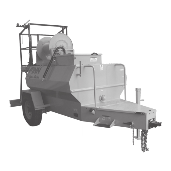
- Page 1 9281 LeSaint Drive • Fairfield, Ohio 45014 Phone (513) 874-2818 • Fax (513) 874-2914 Sales: 1-800-543-7166 T60 II HydroSeeder ® Parts and Operator’s Manual Model SOA Serial No. LBT60-SOA...
-
Page 3: Table Of Contents
The FINN HydroSeeder® and How It Works ........ - Page 4 PARTS SECTION ............31-55 Suction, Discharge, And Recirculation Piping .
-
Page 5: Safety First
SAFETY FIRST With any piece of equipment, new or used, the most important part of its operation is SAFETY! Finn Corporation encourages you and your employees to familiarize yourselves with your new equipment and to stress safe operation. The first six pages of this manual are a summary of all the main safety aspects associated with this unit. -
Page 6: Safety Summary Section
The FINN HydroSeeder® is designed to mix and apply water, seed, fertilizer, agricultural lime and hydraulic mulch to the prepared seedbed. The resultant slurry from mixing one or more of the above materials may react causing harmful or deadly gasses within the tank. - Page 7 or stops. Never operate on a slope or a hill that may 2. Never engage the clutch endanger the driver and/or the operator(s). All per- when both the recirculation sonnel should review and be familiar with stop/start and discharge valves are signals between the driver and operator(s) before closed.
- Page 8 Turn off engine and disconnect battery cables 9. It is recommended that only authorized genuine and perform lockout/tagout procedures. (29 CFR FINN replacement parts be used on the machine. 1910.147) 10. Do not use either cold start fluid if engine is...
- Page 9 CURRENT SET OF SAFETY DECALS ������� WA R NING ������� ������� ������� ������ ������� ��� ������� ��� ��������� ����� ������ ������� ������� ��� ����� ����� ��� �������� ������� ������ ��� ������ ������� ��������� ������ �� ��� ��� ��� �������� ������ ����� �� ������ ������� ���� ������ ����� ��� �������� B U R N H A Z A R D ! ������...
-
Page 10: Operation And Maintenance Section
FINN T60 SERIES II HYDROSEEDER ® This manual gives you step by step instructions for the operation and maintenance of the Finn HydroSeeder®. For best results and to insure longer life of the equipment, please follow the instructions carefully. For your safety read the entire manual before operation of this unit. -
Page 11: Attachments
Mounting the HydroSeeder® to the truck must allow for tire clearance as well as frame twist. Place hard wood spacers along the length of truck rails or use Finn spring mounting kit (#011562) or equivalent. C. Place chains over the HydroSeeder® and around truck bed and secure with binders. Secure the HydroSeeder®... -
Page 12: Pre Start Check
DANGER: The recirculation valve must be open when using a remote valve. If valve is not open, extreme heat will occur resulting in damage and/or bodily injury. 2. Operator’s Platform: A bolt-on package is available to convert the base unit to include an operator’s platform complete with: a discharge boom, guard rails, ladder, and all controls necessary to operate the unit (throttle, clutch control, signal horn, agitator control). - Page 13 Turn thumb nut clockwise until stem rises to maximum height. b) Remove cap and fill cap with sodium (water soluble) base grease. (FINN part number 000698). Do not use lithium base (chassis lube) grease. c) Replace cap.
-
Page 14: Valve Operation (Base Unit)
VALVE OPERATION: A: VALVE OPERATION (BASE UNIT): The base HydroSeeder® is equipped with three (3) independently operated ball valves to control slurry flow (see Figure 2). The first valve is the recirculation valve. An open recirculation valve allows flow back into the tank. -
Page 15: Valve Operation (Platform/Boom Option)
B: VALVE OPERATION (PLATFORM/BOOM OPTION): The platform option is equipped with two (2) independently operated ball valves to control slurry flow (see Figure 3). With the platform option, discharge of the slurry is accomplished two different ways; either through the discharge boom or through a discharge hose which is coupled to the end of the discharge boom. -
Page 16: Starting Procedure
The following tables show loading versus coverage rates for the Finn T60 II. Table A shows rates for “one step” applications. The coverage area is determined by the fiber mulch capacity of the HydroSeeder®, and the rate at which it is applied. - Page 17 TABLE A USING SEED, FERTILIZER AND MULCH Unit Amount of Material in Tank (pounds(kilograms)) Coverage Area Seed Fertilizer Mulch Sq. Ft. (Sq. m.) 46 (21) 53 (24) 200 (91) 5,790 (535) Above Table is based on 1500 pounds of mulch, 400 pounds of fertilizer and 345 pounds of seed (8 pounds/1000 square feet) per acre.
-
Page 18: Tank Capacity Chart
TANK CAPACITY CHART: 600 Gallons BOTTOM T-60 II Gallons in. (cm) From in. (cm) From (liters) Bottom (2271) (20.3) 40.5 (102.9) (2082) 11.25 (28.6) 37.25 (94.6) (1893) 14.25 (36.2) 34.25 (87.) (1703) 16.75 (42.5) 31.75 (80.6) (1514) 19.5 (49.5) (73.7) (1325) (55.9) 26.5... -
Page 19: Loading
LOADING: CAUTION: Take care not to lose pens, lighters, etc. from shirt pockets or drop pieces of paper or plastic bags into the tank, as these might plug the slurry system. 1. With clutch disengaged (off) and agitator control in the neutral position, start engine and allow it to warm up (See starting procedure page 12). -
Page 20: Prior To Application
C. Fertilizer - Cut the fertilizer bag and dump the contents into the slurry tank. D. All other additives - Consult with manufacturer for proper loading technique. 7. When all materials are loaded and in suspension, and the tank is full, move the agitator to neutral then full speed forward to insure all material is mixed. -
Page 21: Application Of Slurry
APPLICATION OF SLURRY: I. GENERAL APPLICATION TECHNIQUES DANGER: Do not spray toward power lines, transformers or other high voltage conductors. CAUTION: The driver of the carrying vehicle should remain alert for hazards to the operator, such as low power lines, hanging branches, etc. -
Page 22: Discharge Through The Boom (Platform Option)
3. With the engine at ¾ speed, open the remote valve at the end of the hose to discharge the load. 4. When finished spraying, close the remote valve, disengage (turn off) the clutch, and stop the engine. If using fiber mulch, retain as much water as possible in the hose by elevating the ends or by cou- pling the ends together. -
Page 23: Weekly Or After Every 40 Hours Of Operation
F. Disengage (turn off) the clutch, idle the engine, move discharge valve handle to discharge position, move agitator handle to neutral and turn off the engine. (Remember to replace the coupler gasket). G. Always remove the drain plug and allow the tank to drain. H. -
Page 24: Hydraulic System
The hydraulic oil filter must be replaced on schedule with a 25 micron absolute filter - Finn part #021618. The hydraulic system relief is factory set at 2250 psi. -
Page 25: Lubrication And Fluids Chart
LUBRICATION AND FLUIDS CHART Ref. No. Location Lubricant Frequency Number Check Grease Level in Pressure Lubricator Daily Grease Agitator Shaft Bearings Daily Grease Discharge Swivel Daily Check Engine Oil Level Daily Change Engine Oil and Filter See Engine Manual Grease Pump Bearings Weekly Check Hydraulic Fluid Level Weekly... -
Page 26: Pump Maintenance
Drive Hub Nut Suction Cover Bolt Clutch Retainer Suction Cover Washer 8 Retainer Bolt Radial Lip Seal Retainer Washer Casing Bearing Clutch Bearing Bolt Clutch Spacer Bearing Washer Pump Frame Frame Bearing NOTE: See Parts Manual for Finn Part Numbers... -
Page 27: A. Factory-Tolerances
A. FACTORY-TOLERANCES. 1. To check pump tolerances loosen the two clamps on the pump suction piping and remove the inlet elbow. Through the pump suction hole, insert a feeler gauge between the pump impeller (3) and the suction cover (1). This measurement on a new pump is between .030-.045 of an inch (.762 -1.15 mm). -
Page 28: Installing New Seal Assembly
D.INSTALLING NEW SEAL ASSEMBLY (#4) (DO NOT uwrap the new seal assembly until you are ready to install. All parts of the assembly are packed in sequence of installation.) 1. To replace the seal assembly (4), perform the above operations under cleaning and remove pump casing (5) by removing the four bolts (7B) holding the casing and the casing bearing (7) to the pump frame (15). - Page 29 Plugging can occur in any of four places; the valve and recirculation nozzle, the discharge nozzle, the pump area and the sump area. Plugging is caused by either foreign objects or dewatered fiber. A. Obstruction in discharge nozzle is determined by a change or stoppage of the spray pattern. a) Disengage (turn off) the clutch.
- Page 30 ® TROUBLE SHOOTING YOUR HYDROSEEDER Problem Probable Causes Suggested Solutions LEAKS: Tank bearing Lack of lubrication - Replace seal and follow lube leaks. seal worn. schedule. Bolts not tightened Tighten uniformly to 25 ft. lbs. properly. Pressure Clamps. Rubber seal cracked, Replace, always grease seal pinched or torn.
- Page 31 ® TROUBLE SHOOTING YOUR HYDROSEEDER Problem Probable Causes Suggested Solutions FOAMING OF SOLUTION AND LACK OF DISTANCE: Pump looses prime - Sucking air in suction Check all suction connections to lacks distance - leaves lines. see that rubber seals are in good excessive amount in tank shape.
- Page 32 ® TROUBLE SHOOTING YOUR HYDROSEEDER Problem Probable Causes Suggested Solutions Constant plugging Machine not being flushed See page 15. during loading and out prior to reloading. discharging. Machine not being run at Reinstruct your operator. (See correct RPM during loading. page 15).
-
Page 33: Notes
NOTES... - Page 34 NOTES...
- Page 35 T60 II Hydroseeder ® Parts Manual Model SOA...
- Page 36 PLATFORM OPTION WHEN ORDERING PARTS, BE SURE TO STATE SERIAL NUMBER OF MACHINE...
- Page 37 SUCTION, DISCHARGE AND RECIRCULATION PIPING Ref. No. Part Number Description No. Req'd Base Platform Base Platform 080520 080520 T60 II Clump Assembly 002383 002383 Pressure Lubricator F60-0022-01 F60-0022-01 Clump Guard 080366 080366 Pipe Clamp 002439 002439 Gasket For 3" Clamp 002868 002868 90°...
- Page 38 WHEN ORDERING PARTS, BE SURE TO STATE SERIAL NUMBER OF MACHINE...
-
Page 39: Clutch/Pump Assembly
CLUTCH/PUMP ASSEMBLY Ref. No Part Number Description No. Req'd 080489 Suction Cover X0720 Suction Cover Bolt Suction Cover Nut 080499 O-Ring 080488 Impeller 080487 Pump Casing 080485 Mechanical Seal X0720 Suction Cover Bolt Suction Cover Washer 080493 Radial Lip Seal 080498 Casing Bearing X0740... - Page 40 WHEN ORDERING PARTS, BE SURE TO STATE SERIAL NUMBER OF MACHINE...
-
Page 41: Hydraulic System
HYDRAULIC SYSTEM Ref. No. Part Number Description No. Req'd 004900 Filler Breather Cap/Dipstick 023616 Straight Adapter 004618 Suction Strainer 080683 Return Hose 080684 Suction Hose 012087 Straight Adapter 080642 Hydraulic Pump 055309 90° Adapter Elbow 080578 Pump Discharge Hose 055238 Straight Adapter 040362 FW71499... -
Page 42: Hydraulic Pump Drive Assembly
HYDRAULIC PUMP DRIVE ASSEMBLY Ref. No. Part Number Description No. Req'd 080642 Hydraulic Pump F60-0016-03 Hydraulic Pump Mounting Plate 080647 Coupling Half - Hydraulic Pump 080324 Coupling Sleeve 085023 Coupling Half - Engine Stub Shaft NOT SHOWN F60-0022-03 Hydraulic Pump Coupling Guard WHEN ORDERING PARTS, BE SURE TO STATE SERIAL NUMBER OF MACHINE... -
Page 43: Hydraulic Agitator Drive Assembly
HYDRAULIC AGITATOR DRIVE ASSEMBLY Ref. No. Part Number Description No. Req'd 080482 Hydraulic Motor F60-0016-01 Torque Arrestor Plate 080523 Rigid Coupling Assembly 007420 Bearing and Seal Assembly (See Pages 40-41) 2 005081-02 Agitator Drive Shaft NOT SHOWN F60-0022-02 Agitator Coupling Guard 080583 Rubber Torque Arrestor Pad 080582... - Page 44 DRIVE NOTE: To tighten, Turn nut not bolt. Torque to 25 Ft. Lbs. 1-1/2" Agitator DO NOT OVER TORQUE Shaft Through Back Side Outside Of Tank Wall Bearing Assy. #007420 (Includes It.'s 1 thur 10) WHEN ORDERING PARTS, BE SURE TO STATE SERIAL NUMBER OF MACHINE...
-
Page 45: Agitator And Bearing Assembly
AGITATOR AND BEARING ASSEMBLY Ref. No. Part Number Description No. Req'd 007420 Bearing and Seal Assembly (Includes It.’s 1 thru 10) 007417 Clamping Ring 1 per 007416 Shaft Seal 1 per 006975 Rubber Flangette Seal 1 per 007212 Flangette w/Groove 1 per 003022 Bearing... -
Page 46: Discharge Boom
DISCHARGE BOOM Ref. No. Part Number Description No. Req'd 080736 Discharge Boom Assembly Consisting of: 080377 Female Coupler 006515 Coupler Gasket 080708 Boom Weldment Z0632SCP Boom Handle Set Screw 080560-02 Adjusting Collar Z0612SCP Boom Collar Set Screw 080559-01 Boom Handle 003299 Discharge Balance Spring 003207... -
Page 47: Hatch Assembly
HATCH ASSEMBLY Ref. No. Part Number Description No. Req'd 080675 Hatch Liner 080674 Hatch Lid 080565-02 Hatch Lid Hinge 005433 Soft Latch 002909 Handle 005565 Hatch Lid Lanyard WHEN ORDERING PARTS, BE SURE TO STATE SERIAL NUMBER OF MACHINE... - Page 48 WHEN ORDERING PARTS, BE SURE TO STATE SERIAL NUMBER OF MACHINE...
- Page 49 COMMON LOOSE PARTS & ENGINE Ref. No. Part Number Description No. Req'd F60-0005 Platform 080678-01 Right Platform Support 080678-02 Left Platform Support 080731 Fill Port Assembly 005280 Fill Port Plug 080378 1-1/2" Male Adapter F60-0002 Tank Top 080589-02 Agitator Control Rod 022801 Clevis 080218...
- Page 50 WHEN ORDERING PARTS, BE SURE TO STATE SERIAL NUMBER OF MACHINE...
-
Page 51: Trailer Assembly Parts
TRAILER ASSEMBLY PARTS Ref. No. Part Number Description No. Req'd 085152 Rubber Mount 005134 Ball Coupler 005135 2-5/16" Ball 080043 Tow Ring 002909 Handle 080591-03 Safety Chain Rod Weldment 023485 Clevis Grab Hook 190033 Safety Chain (3 foot lengths) F60-0015 Fender 080662 6000# Axle Assembly... -
Page 52: Guard Rails
GUARD RAILS Ref. No. Part Number Description No. Req'd 080726 Right Guard Rail 080539-01 Gate 080521 Gate Spring Hinge 080537 Left Guard Rail 080536-18 Top Cross Rail 080536-13 Cross Rail F75-0008 Boom Support Plate 080688 Ladder WHEN ORDERING PARTS, BE SURE TO STATE SERIAL NUMBER OF MACHINE... -
Page 53: Control Panel Wiring
(Black) CLUTCH BUTTON (White) IGNITION (Red) SWITCH CLUTCH SWITCH (Red) (White) (White) HOURMETER CLUTCH (White) HORN HORN BUTTON (Black) ENGINE PLUG CONTROL PANEL WIRING Part Number Description No. Req'd 007274 Hour Meter 080654 Ignition Switch 080654-K Ignition Key 020886 Horn Button 006499 Horn 020886... -
Page 54: Trailer Wiring
(Brown) (Brown) (Red) (Brown) (Yellow) (Green) (Red) (White) STARTER TAIL LIGHTS (Red) (Brown) NOT USED (Brown) LEFT TURN RIGHT TURN (Yellow) (Green) GROUND ELECTRIC BRAKES (White) (Black) TRAILER PLUG CONNECTIONS TRAILER WIRING Ref. No. Part Number Description No. Req'd 075592 7-Blade Trailer Plug 023424 Breakaway Switch... -
Page 55: Tool Kit / Seal Repair Kits
TOOL KIT Part Number Description No. Req'd 000698 Automatic Pressure Lubricator Grease, 1 pound Tub 005220 Impeller Wrench 080273 Long Distance Nozzle Assembly 080131 Long Distance Nozzle 080260 Male Nyglass Adapter 160749 Reducer Bushing 080394 Wide Ribbon Nozzle Assembly 006604 Wide Ribbon Nozzle 080260 Male Nyglass Adapter... - Page 56 NOTE: ITEM #4 (T60T DECAL KIT) INCLUDES ITEMS #5 THRU #35. ������������ ������������ WHEN ORDERING PARTS, BE SURE TO STATE SERIAL NUMBER OF MACHINE...
-
Page 57: Decals
Decal "400 Gallons" 005184 Decal "250 Gallons" 005022 Decal "Use 2-5/16" Ball Only" 080707 Decal "T60T GVWR" 012260 Plate "IMPORTANT! Maintain all Safety Decals . . ." 011690 FINN Name Plate WHEN ORDERING PARTS, BE SURE TO STATE SERIAL NUMBER OF MACHINE... - Page 58 HOSE REEL WIRING MOTOR (Black) CIRCUIT BREAKER SOLENOID STARTER (Red) REEL (Blue) BUTTON WHEN ORDERING PARTS, BE SURE TO STATE SERIAL NUMBER OF MACHINE...
-
Page 59: Hose Reel
HOSE REEL Ref. No. Part Number Description No. Req'd 080316 Hose Reel With 1/2 HP (12V) Motor 008188 Electric Motor 008210 Swivel Joint 080613-01 Live Reel Flat Support 080613-02 Live Reel Angle Support NOT SHOWN 005593 Remote Holder Fab 005210 Lead-In Hose 005592 Soft Latch... -
Page 60: Warranty
Finn to verify said nonconformity and verify the continuing existence of the warranty period, Finn will provide a new part or a repaired part, whichever Finn elects, to replace the part found to be defective. Such parts will be provided without charge to the Purchaser during normal working hours at a place of business of a Finn dealer or other establishment authorized by Finn to effect said repairs or replacements, but Purchaser shall bear all costs of transporting the product to and from such place of business or establishment.
Need help?
Do you have a question about the HydroSeeder T60 II and is the answer not in the manual?
Questions and answers