Table of Contents
Advertisement
Quick Links
Advertisement
Table of Contents

Related Manuals for Xtool D7


Summary of Contents for Xtool D7
- Page 1 D7 Smart Diagnosis System User Manual...
- Page 2 Please read this user manual carefully before using the D7 Smart Diagnosis System. When reading the manual, please pay attention to the words “Note” or “Caution”, and read them carefully for appropriate operation. RADEMARKS is a registered trademark of Shenzhen Xtooltech Intelligent CO., LTD.
-
Page 3: Copyright
(electronic, mechanical, photocopying, recording or other forms). ECLARATION This manual is designed for the usage of D7 Smart Diagnosis System, and provides operating instructions and product descriptions for users of the D7 Smart Diagnostic system. - Page 4 All information, specifications and illustrations in this manual are based on the latest configurations and functions available at the time of printing. Xtool reserves the right to make changes at any time without notice. PERATION NSTRUCTIONS...
- Page 5 Make sure the (DLC) diagnostic link connector is functioning ⚫ properly before starting the test to avoid damage to the Diagnostic Computer. Do not switch off the power or unplug the connectors during ⚫ testing, otherwise you may damage the ECU and/or the Diagnostic Computer.
-
Page 6: Aftersales-Services
FTERSALES ERVICES E-Mail: aftersales-services@xtooltech.com Tel: +86 755 21670995 or +86 755 86267858 (China) Official Website: www.xtooltech.com... -
Page 7: Table Of Contents
ONTENT TRADEMARKS ................I COPYRIGHT ................... II DECLARATION ................II OPERATION INSTRUCTIONS ............III CAUTIONS! .................. IV AFTERSALES-SERVICES ............V CONTENT ..................I GENERAL INTRODUCTION ........... 1 Tablet ..................2 Front View of Tablet..................2 Back View of Tablet ..................3 Host Ports ...................... - Page 8 Main Interface ..............12 Operation system ..................12 Diagnosis system entrance ..............14 Function Buttons ..................15 Navigation Buttons..................16 Notification Bar .................... 17 UPDATE ................. 18 DIAGNOSIS ................19 Vehicle Connection ............. 19 Diagnosis ................20 Vehicle Selection ..................21 Basic functions .....................
- Page 9 Gear Learning ..............37 SRS Reset................37 DPF Regeneration .............. 38 BMS Match ................39 Air Suspension ..............40 Cylinder ................41 TPMS Reset ................ 41 Tyre Refit ................42 Headlight Adjustment ............42 Windows Initialization ............42 Seat Match ................43 Electronic Pump Activation ..........
- Page 10 REPORT ................. 50 REMOTE ASSISTANCE ............51 SHENZHEN XTOOLTECH INTELLIGENT CO., LTD ....53...
-
Page 11: General Introduction
ENERAL NTRODUCTION The XTOOL D7 smart diagnostic system is an advanced flatbed scanning tool based on the Android operating system. It supports multi-language switching and is suitable for different countries and regions. The advantage of this obd2 scanner is not only its... -
Page 12: Tablet
TABLET The main unit of the D7 is the tablet, which has a built-in VCI module, which can be directly connected to the tablet and the car with the main test line, without the need to connect to an external VCI box via Bluetooth. -
Page 13: Back View Of Tablet
BACK VIEW OF TABLET Fig 1-2 Tablet Back View The product model and S/N are laser-engraved on the back of the display tablet, and the small hole at the bottom is the Loudspeaker. ① Nameplate: Display basic information such as S/N and model etc. -
Page 14: Host Ports
HOST PORTS Fig 1-3 Tablet Host Ports ①Micro USB: Battery charge or data synchronization with PC or ②DB15 Port: This port is used to connect to the main test cable. ③Power Button: Long press to power on or off. In the power-on state, short press the button to make the device enter the sleep mode. - Page 15 Memory 32GB 7.0-inch touch screen with 1024 × 600 Display resolution ⚫ Connectivity ⚫ Wi-Fi Sensors Gravity sensor, light sensor Microphone, dual speakers, 4-band 3.5mm Auto Input/Output stereo/standard headset jack Power and Battery 4000mAh, 3.7V lithium-polymer battery Power Voltage Power Consumption Operating Temperature -20 to 60℃(-4 to 140℉) Storage Temperature...
-
Page 16: Package Kit
PACKAGE KIT MAIN UNIT ⚫ Tablet 1 pcs OTHER ACCESSORIES OBDⅡ-16 Connector (1 pcs) ⚫ * Used to access vehicle ECU data ⚫ Main Test Cable (1 pcs) *The main cable is used to connects the Tablet to connector. ⚫ USB Cable *Connect display table to the PC or DC power adapter Power Adapters... -
Page 17: Getting Started
ETTING TARTED GUIDE TO ACTIVATION After first time users press and hold the power button to turn on the system, the system will automatically enter the guide process and request the user to select the system operating language. Fig 2-1 After selecting the system language, click Next to enter the Wi- Fi connection page, as shown below:... - Page 18 Fig 2-2 Select a network to connect to on the Wi-Fi connection page. After successful network connection, the automatic system will jump to Factory mode to download the software: Fig 2-3...
- Page 19 Once the software has been downloaded, the tablet will automatically reboot and request the system language selection again. Fig 2-4 After setting the system language, you will enter the activation page, as shown in the figure below. You can also click the "Trial" button in the upper right corner to try it out before activation.
- Page 20 Fig 2-5 Click Start Activate to enter the activation page, as shown below: Fig 2-6...
- Page 21 A pop-up window showing Activation Success indicates that you have completed the first boot setup, click OK to enter the diagnostic system and start using the device. Fig 2-7...
-
Page 22: Main Interface
MAIN INTERFACE OPERATION SYSTEM As shown in the figure below, this interface is the main page of the operating system of the device. You can also return to this interface at any time by clicking 【⚪】on the bottom navigation bar. Fig 2-8 The icons on the right, from top to bottom, are browser, photo album, application square, file manager, system settings, as... - Page 23 File Explorer Settings for Android System Browser: Click on the browser icon to enter the browser to view the official website of Xtool or search for other information. Gallery: Click the Gallery icon to enter the album to quickly view the pictures or screenshots stored in the device. You...
-
Page 24: Diagnosis System Entrance
Fig 2-9 ES File Explorer: You can manage APP, music, files, pictures, etc. in the device in this function, and you can also use Local/Home/Cleaner to clean up files. DIAGNOSIS SYSTEM ENTRANCE Once activated, you will automatically enter the diagnostic system with the following main screen. -
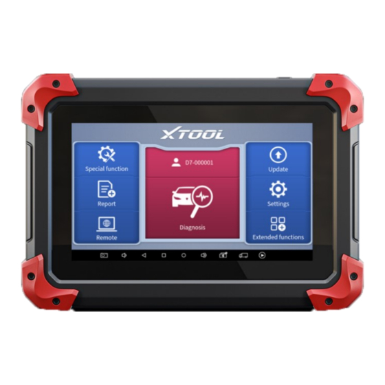
Page 25: Function Buttons
Fig 2-10 The main interface is mainly composed of Function Buttons and Navigation Buttons. The touch screen navigation is menu- driven, and you can quickly access functions by clicking on the option title and answering the dialog window. A detailed description of the menu structure can be found in the next section Function Buttons. -
Page 26: Navigation Buttons
Users can view extended functions such as Xtool Cloud here NAVIGATION BUTTONS Instructions for operating the navigation bar buttons at the bottom of the screen, as described in the table below: Table 2-3... -
Page 27: Notification Bar
Press for screenshot Decrease volume Click this button to return to the diagnostic vehicle interface Increase volume Click here to return to diagnostic vehicle models interface NOTIFICATION BAR Slide down to open the notification bar. User can adjust the brightness of the screen when you need, and you can also connect Wi-Fi and so on. -
Page 28: Update
PDATE After activating the device, please update the software in "Update" first. The device will pull all currently supported software packages, and you can download them as needed. ALL software updates directly via the Internet. To access the update application, open the diagnosis application and click UPDATE, shown as below: Fig 3-1 *Note: After activating the device for the first time, if you do not... -
Page 29: Diagnosis
(ABS), airbag system (SRS), and perform kinds of actuation tests. VEHICLE CONNECTION The diagnosis operation needs to connect the D7 smart diagnosis system to vehicle first, so that the tablet can establish correct vehicle communication. Please perform the following steps: Turn on the tablet;... -
Page 30: Diagnosis
connector should be inserted into the DLC usually located under the vehicle dashboard. The connection method is shown in the figure below: Fig 4-1 ① Tablet ② Main Test Cable ③ OBDII-16 Connector ④ Vehicle *Caution: Please make sure all the cables are connected tightly; The vehicle’s DLC is not always located under the dash;... -
Page 31: Vehicle Selection
VEHICLE SELECTION D7 Smart Diagnosis System support 2 ways to access vehicle diagnosis system. You can select "Automatic Detection" or "Manual Selection" to enter the diagnosis system. Automatic detection will automatically identify the vehicle's VIN code, and then read the information of your target diagnostic object. - Page 32 "manual selection", then you can start the diagnosis by selecting the vehicle brand, year, and model of the vehicle. Enter "manual selection", you can also diagnose the car according to the system according to your needs after selecting the model. Fig 4-3...
-
Page 33: Basic Functions
BASIC FUNCTIONS The diagnosis system supports 5 basic diagnosis functions, as follows: Read ECU ⚫ Read /Clear DTCs ⚫ Read Live Data ⚫ Actuation Test ⚫ Frozen Frame ⚫ Fig 4-4 Read ECU Information: This function is to read ECU version information, which is the equivalent of "System Identification"... - Page 34 It is convenient for us to make record in the maintenance process, and it also makes data feedback and management easier. Fig 4-5 Read Trouble Code: Read trouble codes stored in ECU. Fig 4-6...
- Page 35 *Tip: In the process of diagnosis, if the device shows “System is OK” or “No Trouble Code”, it means there is no related trouble code stored in ECU or some troubles are not under the control of ECU, most of these troubles are mechanical system troubles or executive circuit troubles, it is also possible that signal of the sensor may bias within limits, which can be judged in Live Data.
- Page 36 need record the trouble details after reading code, which is provided as reference for maintenance. After dealing with troubles, there will be no trouble code when we re-read. Read Live Data: that is to read the parameters of running engine, such as oil pressure, temperature, engine speed, fuel oil temperature, coolant temperature, intake air temperature, etc.
- Page 37 stored in ECU or some troubles are not under the control of ECU, most of these troubles are mechanical system troubles or executive circuit troubles, it is also possible that signal of the sensor may bias within limits, which can be judged in Live Data. Actuation Test: mainly to judge whether these actuating components of engine are working properly.
- Page 38 Some vehicles may not have the option of frozen frame, because the model does not support this function.
-
Page 39: Special Functions
PECIAL UNCTIONS The D7 Smart Diagnosis System supports 23 commonly used special reset functions, allowing you to quickly access your vehicle system for various scheduled services, maintenance and reset performance, eliminating the need to reset after resolving common problems. This user manual lists some of the commonly used special reset services for your reference. -
Page 40: Oil Light Reset
D7 are subject to the actual special functions displayed on the device. OIL LIGHT RESET Reset the Engine Oil Life System, which calculates the optimum oil life change interval based on the vehicle's driving conditions and climate. The oil life reminder must be reset each time the oil is changed so that the system can calculate when the next oil change is required. -
Page 41: Abs Bleeding
ABS BLEEDING Anti-lock Braking System (ABS) Bleeding allows you to perform various bi-directional tests to check the operating conditions of ABS. 1. When the ABS contains air, the ABS bleeding function must be performed to bleed the brake system to restore ABS brake sensitivity. -
Page 42: Sas Reset
SAS RESET Steering Angle Sensors (SAS) System Calibration permanently stores the current steering wheel position as the straight-ahead position in the SAS EEPROM. Therefore, the front wheels and the steering wheel must be set exactly to the straight-ahead position before calibration. In addition, the VIN is also read from the instrument cluster and stored permanently in the SAS EEPROM. - Page 43 other device is present. Most new vehicles have an immobilizer as standard equipment. An important advantage of this system is that it doesn’t require the car owner to activate it since it operates automatically. An immobilizer is considered as providing much more effective anti-theft protection than an audible alarm alone.
-
Page 44: Epb Reset
When the ignition switch key, ignition switch, combined instrument panel, ECU, BCM, or remote-control battery is replaced, anti-theft key matching must be performed. The IMMO service can disable a lost vehicle key and program the replacement key fob. One or more replacement key fobs can be programmed. -
Page 45: Tps Match
1. If the brake pad wears the brake pad sense line, the brake pad sense line sends a signal sense line to the on-board computer to replace the brake pad. After replacing the brake pad, you must reset the brake pad. Otherwise, the car alarms. -
Page 46: Gearbox Match
injector code of the corresponding cylinder so as to more accurately control or correct cylinder injection quantity. After the ECU or injector is replaced, injector code of each cylinder must be confirmed or re-coded so that the cylinder can better identify injectors to accurately control fuel injection. *Note 1. -
Page 47: Gear Learning
GEAR LEARNING The crankshaft position sensor learns crankshaft tooth machining tolerance and saves to the computer to more accurately diagnose engine misfires. If tooth learning is not performed for a car equipped with Delphi engine, the MIL turns on after the engine is started. The diagnostic device detects the DTC P1336 'tooth not learned'. -
Page 48: Dpf Regeneration
DPF REGENERATION The Diesel Particle Filter (DPF) function manages DPF regeneration, DPF component replacement teach-in and DPF teach-in after replacing the engine control unit. The ECM monitors driving style and selects a suitable time to employ regeneration. Cars driven a lot at idling speed and low load will attempt to regenerate earlier than cars driven more with higher load and speed. -
Page 49: Bms Match
The PM trap is removed or replaced. ⚫ The fuel additive nozzle is removed or replaced. ⚫ The catalytic oxidizer is removed or replaced. ⚫ The DPF regeneration MIL is on and maintenance is ⚫ performed. The DPF regeneration control module is replaced. ⚫... -
Page 50: Air Suspension
Battery monitoring sensor. Battery matching is performed to ⚫ re-match the control module and motoring sensor to detect battery power usage more accurately, which can avoid an error message displaying on the instrument panel. AIR SUSPENSION This function can adjust the height of the vehicle body. When replacing the body height sensor in the air suspension system, or control module or when the vehicle level is incorrect, you need to perform this function to adjust the body height sensor for level... -
Page 51: Cylinder
CYLINDER This function is suitable for power balance after replacing and repairing the cylinder. TPMS RESET Tire Pressure Monitor System (TPMS) Reset allows you to quickly look up the tire sensor IDs from the vehicle ECU, as well as to perform TPMS replacement and reset procedures after tire sensors are replaced. -
Page 52: Tyre Refit
sensor is damaged, and tire is replaced for the car with tire pressure monitoring function. TYRE REFIT This function is used to set the size parameters of refitting or replacing tires. HEADLIGHT ADJUSTMENT Refers to the adaptive front lighting system (when using bi-xenon headlights at night), it can be rotated to both sides, pressing the button means that they stay in direct light, and will not turn when you turn the steering wheel. -
Page 53: Seat Match
SEAT MATCH This function is suitable for the matching of replacement and maintenance seats with memory function. After the seat fails or is replaced or repaired, it is generally necessary to use this function to match the seat. *Cautions: Needed for cars with seats with memory function, general gasoline cars don’t need. -
Page 54: Eeprom Adapter
The EEPROM adapter is not included in this product. Please purchase it separately if you need to use it. ETTINGS Click the Settings button to adjust the default settings and view information about the D7 Smart Diagnosis System. There are seven options available in the system settings:... -
Page 55: Language
Language ⚫ Units ⚫ My Workshop Info ⚫ VCI Info ⚫ About ⚫ LANGUAGE Select the language. Please choose the right language from the multi-language options on the right. Fig 6-1 *Note: The types and quantities of languages supported are subject to the actual language types displayed on the device... -
Page 56: Units
UNITS You can switch the unit used by the system. D7 Smart Diagnosis System provides you with metric and imperial units. You can directly click on the unit you need, after the switch is successful, a blue check mark will be displayed behind the unit’s name. -
Page 57: Vci Information
including your company name, address, website, telephone, and mailbox. Fig 6-3 VCI INFORMATION You can view the VCI information here, including the VCI firmware name, the latest firmware version, the currently used firmware version, and the VCI firmware type. If the current firmware version is lower than the latest firmware version, you can choose to update your firmware version and click "Update VCI Firmware"... -
Page 58: About
Fig 6-4 ABOUT Tap on ABOUT, you can check the serial number and APP version on here. - Page 59 Fig 6-5...
- Page 60 EPORT Diagnostic Report is used for viewing and printing the saved files, such as Live Data, Trouble codes or pictures generated in the process of diagnosis, users also can view a record of which cars have been previously tested. It includes 3 parts: Report ⚫...
- Page 61 If you encounter problems and are not able to solve them, you could open this application and ask for remote assistance. To obtain remote support from your partners or Xtool After- service Center: 1. Turn on the power of the tablet.
- Page 62 4. Provide your ID to the partner or Xtool technician, and then wait for him/her to send you a remote-control request.
- Page 63 ., L HENZHEN TOOLTECH NTELLIGENT Company address: 17&18/F, Building A2, Creativity City, Liuxian Avenue, Nanshan District, Shenzhen, China Factory address: 2/F, Building 12, Tangtou Third Industrial Zone, Shiyan Street, Baoan District, Shenzhen, China Service Hotline: 0086-755-21670995/86267858 Email: marketing@xtooltech.com Fax: 0755-83461644 Website: www.xtooltech.com...
Need help?
Do you have a question about the D7 and is the answer not in the manual?
Questions and answers