
Related Manuals for Dell Vostro 15


Summary of Contents for Dell Vostro 15
- Page 1 Dell Vostro 15–3568 Owner's Manual Regulatory Model: P63F Regulatory Type: P63F002 September 2021 Rev. A04...
- Page 2 Un mensaje de AVISO indica el riesgo de daños materiales, lesiones corporales o incluso la muerte. © 2018-2021 Dell Inc. o sus subsidiarias. Todos los derechos reservados. Dell, EMC y otras marcas comerciales son marcas comerciales de Dell Inc. o sus filiales. Otras marcas comerciales pueden ser marcas comerciales de sus respectivos propietarios.
-
Page 3: Table Of Contents
Contents Chapter 1: Trabajo en el equipo......................7 Safety instructions................................7 Before working inside your computer..........................7 Apagado del equipo................................8 Turning off your — Windows............................. 8 Apagado del equipo (Windows 7)..........................8 Después de manipular el interior del equipo........................8 Chapter 2: Disassembly and reassembly..................10 Herramientas recomendadas............................10 Screw size list.................................. - Page 4 Placa del botón de encendido............................27 Removing the power button board......................... 27 Installing the power button board........................... 27 Heat sink .................................... 28 Removing the heat sink ............................28 Installing the heat sink .............................. 28 System fan..................................29 Removing the system fan............................29 Installing the system fan............................30 Altavoz....................................
- Page 5 Conjunto de chips................................52 Descarga del controlador del conjunto de chips....................53 Identificación del conjunto de chips en el Administrador de dispositivos en Windows 10......53 Identificación de conjuntos de chips en el Administrador de dispositivos en Windows 8......53 Identificación de conjuntos de chips en el Administrador de dispositivos en Windows 7......54 Controladores del conjunto de chips Intel......................
- Page 6 Chapter 6: Technical specifications..................... 77 Chapter 7: Contacting Dell......................81 Contents...
-
Page 7: Chapter 1: Trabajo En El Equipo
Damage due to servicing that is not authorized by Dell is not covered by your warranty. Read and follow the safety instructions that came with the product. -
Page 8: Apagado Del Equipo
CAUTION: To disconnect a network cable, first unplug the cable from your computer and then unplug the cable from the network device. 5. Disconnect all network cables from the computer. 6. Disconnect your computer and all attached devices from their electrical outlets. 7. - Page 9 Para evitar daños en la computadora, utilice únicamente la batería diseñada específicamente para esta computadora Dell. No utilice baterías diseñadas para otros equipos Dell. 1. Conecte los dispositivos externos, como un replicador de puerto o la base para medios y vuelva a colocar las tarjetas, como una tarjeta ExpressCard.
-
Page 10: Chapter 2: Disassembly And Reassembly
Los procedimientos de este documento requieren el uso de las siguientes herramientas: ● Destornillador Phillips núm. 0 ● Destornillador Phillips núm. 1 ● Un objeto puntiagudo de plástico Screw size list Table 1. Vostro 15–3562 screw size list M2L2(Bi M2L2(Bi M2.5L2. Component M2L3 M2.5L8... -
Page 11: Vista Del Chasis
Table 1. Vostro 15–3562 screw size list (continued) M2L2(Bi M2L2(Bi M2.5L2. Component M2L3 M2.5L8 M2L5 5 (Big M3L3 M2L3 M2L2 head07) head05) head) Hard drive bracket WLAN card System fan System board I/O board Power connector Display assembly Display panel... -
Page 12: Left View
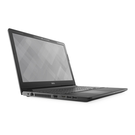
1. Cámara 2. Indicador luminoso de estado de la cámara 3. Micrófono 4. Panel LCD 5. Indicador luminoso de estado de la batería y de alimentación/Indicador luminoso de actividad del disco duro Left view 1. Power connector 2. Network connector (No LED indicator) 3. -
Page 13: Vista Del Reposamanos
Vista del reposamanos 1. Botón de encendido 2. Teclado 3. Reposamanos 4. Superficie táctil Right view 1. SD card reader 2. Universal audio port Disassembly and reassembly... -
Page 14: Battery
3. USB 2.0 connector 4. Optical drive 5. Security cable slot Battery Extracción de la batería 1. Siga los procedimientos que se describen en Antes de manipular el interior del equipo. 2. Para extraer la batería: a. Deslice los pestillos de liberación para desbloquear la batería [1]. b. -
Page 15: Unidad Óptica
Unidad óptica Removing the optical drive 1. Follow the procedure in Before working inside your computer. 2. Remove the battery. 3. To remove the optical drive: a. Remove the two M2L3 screws that secure the optical drive to the computer [1]. b. -
Page 16: Installing The Optical Drive Bracket
Installing the optical drive bracket 1. Install the optical drive bracket. 2. Tighten the single M2L2(Big head05) screw to secure the optical drive bracket. 3. Install the: optical drive battery 4. Follow the procedure in After working inside your computer. Installing the optical drive 1. - Page 17 4. To remove the keyboard cable: a. Disconnect the keyboard cable from the system board. b. Remove the keyboard from the computer. Disassembly and reassembly...
-
Page 18: Installing The Keyboard
Installing the keyboard 1. Connect the keyboard cable to the connector on the system board. 2. Slide the keyboard to align it with the tabs. 3. Press along the top edges to lock the keyboard in place. 4. Install the battery. 5. - Page 19 4. Flip the computer and remove the screws (3 screws - M2L2; 2 screws- M2L2; 8 screws - M2.5L8) that secure the base cover to the computer. Disassembly and reassembly...
- Page 20 5. To remove the base cover: a. Use a scribe to pry the edges of the base cover [1]. b. Lift the base cover and remove it from the computer [2]. Disassembly and reassembly...
-
Page 21: Installing The Base Cover
Installing the base cover 1. Align the base cover with the screw holders on the computer. 2. Press the edges of the cover until it clicks into place. 3. Tighten the ( 8 screws - M2.5L8; 3 screws - M2L2; 2 screws- M2L2) screws to secure the base cover to the computer. 4. -
Page 22: Removing The Hard Drive From The Hard Drive Bracket
base cover 3. To remove the hard drive assembly: a. Disconnect the hard drive cable from the connector on the system board [1]. b. Remove the four M2L3 screws that secure the hard drive assembly to the computer [2]. c. Lift the hard drive assembly away from the computer [3]. Removing the hard drive from the hard drive bracket 1. -
Page 23: Installing The Hard Drive Into The Hard Drive Bracket
Installing the hard drive into the hard drive bracket 1. Align the screw holders and insert the hard drive into the hard drive bracket. 2. Tighten the four M3L3 screws to secure the hard drive to the hard drive bracket. 3. -
Page 24: Installing The Wlan Card
3. To remove the WLAN card: a. Remove the single M2L3 screw that secures the tab to the WLAN card [1]. b. Lift the tab that secures the WLAN card [2]. c. Disconnect the WLAN cables from the connectors on the WLAN card [3]. d. -
Page 25: Instalación Del Módulo De Memoria
2. Remove the: battery optical drive keyboard base cover 3. To remove memory module: a. Pull the clips securing the memory module until the memory module pops up [1]. b. Remove the memory module from the system board [2]. Instalación del módulo de memoria 1. -
Page 26: Coin-Cell Battery
Coin-cell battery Removing the coin cell battery 1. Follow the procedure in Before working inside your computer. 2. Remove the: battery optical drive keyboard base cover 3. Use a plastic scribe to lift the battery out of the slot [1,2]. Instalación de la batería de tipo botón 1. -
Page 27: Placa Del Botón De Encendido
Placa del botón de encendido Removing the power button board 1. Follow the procedure in Before working inside your computer. 2. Remove the: battery optical drive keyboard base cover 3. To remove the power button board: a. Disconnect the system board cable from the computer [1]. b. -
Page 28: Heat Sink
6. Tighten the two (M2.5L8) screws to secure the display hinge to the power button board. 7. Install the: base cover keyboard optical drive battery 8. Follow the procedures in After working inside your computer. Heat sink Removing the heat sink 1. -
Page 29: System Fan
2. Tighten the four captive screws to secure it to the system board. NOTE: Secure the screws in the order of the callout numbers [1, 2, 3, 4]. 3. Install the: base cover keyboard optical drive battery 4. Follow the procedures in After working inside your computer. -
Page 30: Installing The System Fan
Installing the system fan 1. Align the system fan on the chassis. 2. Secure the system fan to the computer by tightening the two M2L5 screws. 3. Connect the system fan connector cable to the system board connector. 4. Install the: base cover keyboard optical drive... -
Page 31: Installing The Speakers
Installing the speakers 1. Place the speakers into the slots on the computer. 2. Connect the speaker cable to the system board. 3. Install the: base cover keyboard optical drive battery 4. Follow the procedure in After working inside your computer Placa base Removing the system board 1. - Page 32 memory module heat sink system fan 3. Remove the screw and lift the display hinge from the computer [1, 2]. 4. Lift the locking tab to disconnect the following cables a. hard drive connector [1] b. power connector [2] c. remove the adhesive tape [3] d.
- Page 33 5. Remove the two M2L3 screws that secure the system board to the computer [1] and lift the system board [2]. Disassembly and reassembly...
- Page 34 6. Flip the system board. 7. To remove the system board: a. Peel the adhesive tape [1]. b. Unlock the tab and disconnect the power cable [2]. c. Remove the system board from the computer. Disassembly and reassembly...
-
Page 35: Installing The System Board
Installing the system board 1. Connect the power cable cable. 2. Affix the adhesive tape. 3. Flip the system board. 4. Align the system board with the screw holders on the computer. 5. Tighten the two M2L3 screws to secure the system board to the computer. 6. -
Page 36: Input-Output Board
Input-Output board Removing the Input-Output board 1. Follow the procedure in Before working inside your computer. 2. Remove the: battery optical drive keyboard base cover hard drive assembly 3. To remove the Input/Output board (I/O board): a. Disconnect the I/O board cable [1]. b. -
Page 37: Puerto Del Conector De Alimentación
optical drive battery 4. Follow the procedure in After working inside your computer. Puerto del conector de alimentación Removing the power connector 1. Follow the procedure in Before working inside your computer. 2. Remove the: battery optical drive keyboard base cover hard drive assembly WLAN card memory module... -
Page 38: Installing The Power Connector
Installing the power connector 1. Insert the power connector into the slot on the computer. 2. Secure the power connector to the computer by using the single [ M2x2 (Big head 07)] screw. 3. Route the power connector cable. 4. Install the: system board system fan WLAN Card... - Page 39 4. Flip the computer. 5. To remove the display assembly: NOTE: Place the chassis on the edge of a table with the display facing down. a. Remove the three M2.5L8 screws that secure the display hinge to the computer [1]. Disassembly and reassembly...
-
Page 40: Installing The Display Assembly
CAUTION: Practice caution when handling the LCD HUD by supporting it with one hand, while working on the hinges. b. Lift and remove the display assembly [2]. Installing the display assembly 1. Align the display assembly with the chassis. 2. Connect the eDP cable to the connector on the system board and lock the locking tab. 3. -
Page 41: Embellecedor De La Pantalla
Embellecedor de la pantalla Removing the display bezel 1. Follow the procedure in Before working inside your computer. 2. Remove the: battery optical drive keyboard base cover WLAN card display assembly 3. To disconnect the display bezel: a. Use a plastic scribe to release the tabs on the edges to release the display bezel from the display assembly. b. -
Page 42: Camera
Camera Removing the camera 1. Follow the procedure in Before working inside your computer. 2. Remove the: battery optical drive keyboard base cover WLAN card display assembly display bezel 3. To remove the camera: a. Disconnect the camera cable from the camera [1]. b. -
Page 43: Panel De La Pantalla
battery 4. Follow the procedure in After working inside your computer. Panel de la pantalla Removing the display panel 1. Follow the procedure in Before working inside your computer. 2. Remove the: battery optical drive keyboard base cover WLAN card display assembly display bezel 3. -
Page 44: Installing The Display Panel
Installing the display panel 1. Connect the eDP cable to the display panel. 2. Affix the tape to secure the display cable. 3. Place the display panel on the display assembly. 4. Tighten the M2.5L8 screws to secure the display panel to the display assembly. 5. -
Page 45: Installing The Display Hinges
display assembly display bezel display panel 3. To remove the hinges: a. Remove the six M2.5L2.5 screws that secure the display hinges to the display assembly [1]. b. Remove the display hinges [2]. Installing the display hinges 1. Tighten the six M2.5L2.5 screws to secure the display hinges to the display assembly. 2. - Page 46 optical drive keyboard base cover hard drive assembly WLAN card memory module speaker heat sink system fan system board 3. To remove the screw support bracket: a. Remove the M2L3 screw that secures the screw support bracket to the computer [1]. b.
- Page 47 5. To remove the touchpad board: a. Remove the four M2L2 screws that secure the touchpad board to the computer [1]. b. Lift and remove the touchpad board [2]. Disassembly and reassembly...
-
Page 48: Installing The Touchpad
Installing the touchpad 1. Place the touchpad board into the slot. 2. Replace the four M2L2 screws to secure the touchpad board to the computer. 3. Replace the two M2L3 screws to secure the touchpad support bracket to the touchpad board. 4. -
Page 49: Installing The Palmrest
Installing the palmrest 1. Place the palmrest. 2. Install the: display assembly system board power connector port I/O board speaker system fan heat sink power button board memory module WLAN Card hard drive assembly base cover keyboard optical drive battery 3. -
Page 50: Chapter 3: Tecnología Y Componentes
Tecnología y componentes Temas: • Processors • Conjunto de chips • Intel HD Graphics • Opciones de pantalla • Opciones de disco duro • USB features • HDMI 1.4 • Características de la cámara • Memory features • Audio drivers Processors This laptop is shipped with Intel 6th generation processor: ●... -
Page 51: Identificación De Los Procesadores En Windows 7
Se muestra la información básica del procesador. Identificación de los procesadores en Windows 7 1. Haga clic en Inicio > Panel de control > Administrador de dispositivos. 2. Seleccione Procesador. Se muestra la información básica del procesador. Verificación del uso del procesador en Administrador de tareas 1. -
Page 52: Verificación Del Uso Del Procesador En El Monitor De Recursos
Se muestra la ventana del Administrador de tareas de Windows. 3. Haga clic en la pestaña Rendimiento en la ventana del Administrador de tareas de Windows. Se muestra la información sobre el rendimiento del procesador. Verificación del uso del procesador en el Monitor de recursos 1. -
Page 53: Descarga Del Controlador Del Conjunto De Chips
Descarga del controlador del conjunto de chips 1. Encienda el portátil. 2. Vaya a Dell.com/support. 3. Haga clic en Soporte de producto, introduzca la etiqueta de servicio de su portátil y haga clic en Enviar. NOTA: Si no tiene la etiqueta de servicio, utilice la función de detección automática o busque de forma manual el modelo de su portátil. -
Page 54: Identificación De Conjuntos De Chips En El Administrador De Dispositivos En Windows 7
Identificación de conjuntos de chips en el Administrador de dispositivos en Windows 7 1. Haga clic en Inicio →Panel de control →Administrador de dispositivos. 2. Amplíe Dispositivos del sistema y busque el conjunto de chips. Controladores del conjunto de chips Intel Compruebe si los controladores del conjunto de chips de Intel ya están instalados en el portátil. -
Page 55: Intel Hd Graphics
Intel HD Graphics This laptop is shipped with the Intel HD Graphics graphics chipset. Controladores Intel HD Graphics Compruebe si los controladores Intel HD Graphics ya están instalados en el portátil. Tabla 3. Controladores Intel HD Graphics Antes de la instalación Después de la instalación Opciones de pantalla Este portátil cuenta con una pantalla HD de 15 pulgadas con una resolución (máxima) de 1366 x 768 píxeles. -
Page 56: Descarga De Controladores
● tecla de flecha hacia la izquierda (Rotar 270 grados) Descarga de controladores 1. Encienda el portátil. 2. Vaya a Dell.com/support. 3. Haga clic en Soporte de producto, introduzca la etiqueta de servicio de su portátil y haga clic en Enviar. NOTA: Si no tiene la etiqueta de servicio, utilice la función de detección automática o busque de forma manual el modelo... -
Page 57: Ajuste Del Brillo En Windows 8
3. Utilice el control deslizante Ajustar el brillo de la pantalla automáticamente para activar o desactivar el ajuste automático del brillo. NOTA: También puede utilizar el control deslizante Nivel de brillo para ajustar el brillo de forma manual. Ajuste del brillo en Windows 8 Para activar o desactivar el ajuste automático del brillo de la pantalla: 1. -
Page 58: Opciones De Disco Duro
Acceso a la configuración del BIOS 1. Encienda o reinicie el portátil. 2. Cuando aparezca el logotipo de Dell, realice una de las siguientes acciones para acceder al programa de configuración del BIOS: ● Con el teclado: toque la tecla F2 hasta que aparezca el mensaje de acceso a la configuración del BIOS. Para entrar en el menú... -
Page 59: Usb Features
La unidad de disco duro aparece en Información del sistema bajo el grupo General. USB features Universal Serial Bus, or USB, was introduced in 1996. It dramatically simplified the connection between host computers and peripheral devices like mice, keyboards, external drivers, and printers. Table 4. - Page 60 ● USB 2.0 previously had four wires (power, ground, and a pair for differential data); USB 3.0/USB 3.1 Gen 1 adds four more for two pairs of differential signals (receive and transmit) for a combined total of eight connections in the connectors and cabling.
-
Page 61: Hdmi 1.4
HDMI 1.4 This topic explains the HDMI 1.4 and its features along with the advantages. HDMI (High-Definition Multimedia Interface) is an industry-supported, uncompressed, all-digital audio/video interface. HDMI provides an interface between any compatible digital audio/video source, such as a DVD player, or A/V receiver and a compatible digital audio and/or video monitor, such as a digital TV (DTV). -
Page 62: Identificación De La Cámara En El Administrador De Dispositivos En Windows 8
Inicio de la cámara Para iniciar la cámara, abra una aplicación que utilice la cámara. Por ejemplo, si toca el software Dell Webcam Central o el software Skype que se envía con el portátil, la cámara se encenderá. De forma similar, si está conversando en Internet y la aplicación solicita acceder a la cámara web, la cámara web también se encenderá. -
Page 63: Memory Features
2. Seleccione Cámara en la lista aplicaciones. 3. Si la aplicación de la cámara no está disponible en la lista aplicaciones, búsquela. Memory features This Laptop supports 4 GB to 16 GB, 2133 MHz DDR4 SoDIMM (2 slot). Tecnología y componentes... -
Page 64: Verifying System Memory
● With keyboard — Press F2. ● Without keyboard — Press and hold the Volume Up button when the Dell logo is displayed on the screen. When the F12 boot selection menu is displayed, select Diagnostics from the boot menu, and press Enter. -
Page 65: Chapter 4: System Setup
Boot sequence enables you to bypass the System Setup–defined boot device order and boot directly to a specific device (for example: optical drive or hard drive). During the Power-on Self-Test (POST), when the Dell logo appears, you can: ● Access System Setup by pressing F2 key ●... -
Page 66: Keyboards Hot Key Definitions
Keys Navigation Moves to the previous page until you view the main screen. Pressing Esc in the main screen displays a message that prompts you to save any unsaved changes and restarts the system. Keyboards Hot Key Definitions Table 6. Keyboards Hot Key Definitions Keys Description Fn + ESC... - Page 67 Tabla 7. Pestaña general Opción Descripción System Information En esta sección se enumeran las principales características de hardware del equipo. ● System Information (Información del sistema): muestra la versión del BIOS, la etiqueta de servicio, la etiqueta de inventario, la etiqueta de propiedad, la fecha de propiedad, la fecha de fabricación y el código de servicio rápido.
- Page 68 Tabla 8. Configuración del sistema (continuación) Opción Descripción USB Configuration Este campo configura la controladora USB integrada. Si la opción Boot Support (Compatibilidad de inicio) está activada, el sistema puede iniciarse desde cualquier tipo de dispositivo de almacenamiento masivo USB (unidad de disco duro interna, memoria USB, disquete).
- Page 69 Tabla 10. Seguridad (continuación) Opción Descripción Strong Password Permite establecer como obligatoria la opción de establecer siempre contraseñas seguras. Configuración predeterminada: la opción Enable Strong Password (Activar contraseña segura) no está seleccionada. NOTA: Si se ha activado la opción Strong Password (Contraseña segura), las contraseñas de administrador y del sistema deben contener como mínimo un carácter en mayúscula y un carácter en minúscula, y deben tener una longitud mínima de 8 caracteres.
- Page 70 Tabla 10. Seguridad (continuación) Opción Descripción Admin Setup Lockout Permite impedir que los usuarios entren en el programa de configuración cuando hay establecida una contraseña de administrador. Configuración predeterminada: la opción Enable Admin Setup Lockout (Activar bloqueo de configuración de administrador) no está seleccionada. Tabla 11.
- Page 71 Tabla 13. Performance Opción Descripción Multi Core Support Este campo especifica si el proceso tendrá uno o todos los núcleos activados. El rendimiento de algunas aplicaciones mejorará con los núcleos adicionales. Esta opción está activada de forma predeterminada. Permite habilitar o deshabilitar la compatibilidad de varios núcleos con el procesador.
- Page 72 Tabla 14. Power Management (continuación) Opción Descripción Advanced Battery Charge Esta opción permite maximizar el estado de la batería. Si se habilita esta opción, el Configuration sistema utiliza el algoritmo estándar de carga y otras técnicas durante las horas de no trabajo para maximizar el estado de la batería.
-
Page 73: Updating The Bios In Windows
If the recovery key is not known this can result in data loss or an unnecessary operating system re-install. For more information on this subject, see Knowledge Base Article: https://www.dell.com/support/kbdoc/000134415/. 1. Restart the computer. -
Page 74: System And Setup Password
2. Go to Dell.com/support. ● Enter the Service Tag or Express Service Code and click Submit. ● Click Detect Product and follow the instructions on screen. 3. If you are unable to detect or find the Service Tag, click Choose from all products. -
Page 75: Deleting Or Changing An Existing System Setup Password
Deleting or changing an existing system setup password Ensure that the Password Status is Unlocked (in the System Setup) before attempting to delete or change the existing System and Setup password. You cannot delete or change an existing System or Setup password, if the Password Status is Locked. -
Page 76: Chapter 5: Enhanced Pre-Boot System Assessment - Epsa Diagnostics
Invoke diagnostics boot by either of the methods that are suggested below: 1. Power on the computer. 2. As the computer boots, press the F12 key when the Dell logo is displayed. 3. In the boot menu screen, use Up/Down arrow key to select the Diagnostics option and then press Enter. - Page 77 Technical specifications NOTE: Offerings may vary by region. For more information regarding the configuration of your system in: ● Windows 10, click or tap Start > Settings > System > About. Table 22. System specifications Feature Specification Chipset Intel Kaby Lake DRAM bus width 64 bits Flash EPROM...
- Page 78 Table 26. Audio specifications (continued) Feature Specification Interface Intel HDA bus Speakers 2 x 2 W Volume controls Program menu and keyboard media-control keys Table 27. Video specifications Feature Specification Video type Video Controller: Intel HD Graphics (shared memory) Discrete AMD Radeon R5 M315 (up to 2 GB DDR3) Data bus: 64 bits...
- Page 79 Table 31. Display specifications (continued) Feature Specification Width 224.3 mm (8.83 inches) Maximum resolution 1366 x 768 pixels Active area (X/Y) 344.20 mm x 193.50 mm (13.55 inches x 7.62 inches) Maximum brightness 200 nits Operating angle 0° (closed) to 135° Refresh rate 60 Hz Minimum viewing angles:...
- Page 80 Table 35. AC Adapter specifications (continued) Feature Specification Input voltage 100 V AC–240 V AC Input frequency 50 Hz–60 Hz Input current (maximum) 65 W 1.70 A Output current 65 W 3.34 A (continuous) Rated output voltage 19.5 V DC Temperature range: Operating -40°C to 21.1°C (-40°F to 70°F)
- Page 81 Dell provides several online and telephone-based support and service options. Availability varies by country and product, and some services may not be available in your area. To contact Dell for sales, technical support, or customer service issues: 1. Go to Dell.com/support.