
Related Manuals for Select Engineered Systems TEC Series


Summary of Contents for Select Engineered Systems TEC Series
- Page 1 TEC Series v 3.2X TEC Series Telephone Access TEC 2 TEC 4 600TECMANUAL TEC 10 Mar. 2015 Select Engineered Systems, Inc. Page First...
- Page 2 TEC Series v 3.2X INTRODUCTION TEC SERIES STANDARD FEATURES CUSTOMIZING FEATURES OPTIONS ENVIRONMENT CONSIDERATIONS ELECTRICAL REQUIREMENTS TECHNICAL DATA INSTALLATION GENERAL WIRE SPECIFICATIONS TERMINAL WIRING HOOKUP CONNECTIONS TERMINAL BARRIER STRIP CONNECTION DESCRIPTION DIP SWITCH SETTINGS SPEAKER SETTINGS MICROPHONE SETTINGS POWER SWITCH...
- Page 3 TEC Series v 3.2X PROGRAMMING 25 - 68 QUICK KEYPAD EXAMPLE TOUCH TONE INITIALIZATION 27 - 49 MANAGER PASSCODE 50 - 68 PROGRAMMING CHOICES KEYPAD CODES / NAMES ADD / FIND NAME DELETING A CODE DELETING A CODE FIELD CODES USED...
- Page 4 TEC Series v 3.2X PROGRAMMING continued CLOCK SETUP SETTING TIME/DATE SETTING TIME ZONES SETTING HOLIDAYS ACCESS LEVELS SELECTING AN ACCESS GROUP SELECTING AN ACCESS LEVEL PROGRAMMING AN ACCESS LEVEL - TABLE AUTOMATIC UNLOCK AND RELOCK BY TIME ZONE EXAMPLE OF AN AUTOMATIC UNLOCK APPLICATION...
- Page 5 TEC Series v 3.2X TERMINAL PROGRAMMING continued ENTRANCE X UNLOCK TIME ENTRANCE X UNLOCK TONE ENTRANCE X AUTO GROUP ENTRANCE X LATCH TONE ENTRANCE X SPECIAL RELAY ENABLE SYSTEM PARAMETERS TALK TIME ALARM TIME CODE LENGTH PIN LENGTH BACK BEEP TONE DIAL UNIT ID.
- Page 6 TEC Series v 3.2X TERMINAL PROGRAMMING continued SET PARAMETERS CLEAR TIME ZONES CLEAR HOLIDAYS CLEAR ACCESS LEVELS CLEAR ACCESS GROUPS CLEAR CORRUPT DATA DISPLAY DATA PRINT INFO PRINT HOLIDAYS PRINT ACCESS LEVELS PRINT ACCESS GROUPS DISPLAY TIME ZONE DISPLAY HOLIDAYS...
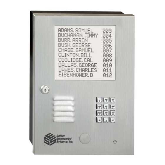
- Page 7 The TEC units operate and program identically. In this manual, the term "TEC" will be used interchangeably to refer to any type of unit. The TEC series line includes a 2 line display LCD display called the TEC2, a 4 line LCD display called the TEC4, and a 10 name LCD display called the TEC10.
- Page 8 TEC Series v 3.2X INTRODUCTION STANDARD FEATURES: • Memory Capacities: 50/125/250/500/1000/2000 for residents telephone numbers and names in directory. • Dials out either Touch-Tone™ or rotary - field programmable. • Dials up to 14 digit phone numbers. • Unit will mute tones in speaker during dialing.
- Page 9 TEC Series v 3.2X STANDARD CUSTOMIZING FEATURES continued • Hide Name Feature. Allows people to dial a code without displaying name on directory. • Two minute modem lockout time. • Dynamic scrolling, based on number of phone numbers programmed (See table below).
- Page 10 INTRODUCTION TEC Series v 3.2X ENVIRONMENTAL CONSIDERATIONS Indoor or Outdoor: The standard TEC housing is suitable for indoor or outdoor installations. For semi-flush installations, contact SES about the optional flush ring (OPTFLR). For surface mount installations, contact SES for the optional trim ring (OPTSL-2). Optional pedestal mounts for curb (PST236), or street (PST242).
- Page 11 TEC Series v 3.2X INSTALLATION INSTRUCTIONS INSTALLATION INSTRUCTIONS NOTE THE FOLLOWING BEFORE ATTEMPTING ANY INSTALLATION: 1. Never install telephone wiring during a lightning storm. 2. Never install telephone jacks in wet locations unless the jack is specifically designed for wet locations.
- Page 12 TEC Series v 3.2X INSTALLATION INSTRUCTIONS WIRING HOOKUP CONNECTIONS TBS = TERMINAL BARRIER STRIP TBS-2 PHONE LINE MODULAR PLUG TO RJ-11 JACK TBS-3 TBS-5 POWER 16 GA. TWIST TRANS- FORMER 50 FEET MAX DIST. 16.5VAC TBS-6 20VA Entrance 1 Entrance 2...
- Page 13 TEC Series v 3.2X INSTALLATION INSTRUCTIONS TERMINAL BARRIER STRIP CONNECTIONS USE 16 GA. OR LARGER TEC UNIT MUST BE GROUNDED FOR ALL SHIELDS TELEPHONE LINE CONNECTS HERE TELEPHONE LINE CONNECTS HERE Not Used SES SUPPLIED TRANSFORMER 16 GA. TO 50 FT.
- Page 14 TEC Series v 3.2X INSTALLATION. J202 1&2 J201 1&2 Relay Jumper Selections Shown N/C Move both jumpers for each relay (J201-1&2 for Entrance 1) to make N/C (J202-1&2 for Entrance 2) Entrance 2 Entrance 1 Shown N/O Move both jumpers for each to...
- Page 15 TEC Series v 3.2X POWER SWITCH LOCATION POWER PHONE LINE CONNECTOR POLYSWITCHES POWER SWITCH TURN OFF BEFORE INSTALLING OR REMOVING ACCESSORIES. POW ER LED Page 9...
- Page 16 TEC Series v 3.2X ACCESSORIES OVERVIEW Although some options are not shown, available options are: • External Card reader(s) input (2 or 4 Readers) • Wiegand, Proximity, RF Transmitter, Barcode (Wiegand output). • Several reader technologies using Wiegand format signals are available, including Wiegand, Proximity, RF Transmitter, and Long Range Proximity Readers.
- Page 17 TEC Series v 3.2X ACCESSORY INSTALLATION (OPTIONAL) WIEGAND INPUT MODULES The TEC OPTIONALLY can be equipped with two or four internal card reader inputs. The card reader modules work with 26 or 30 bit Wiegand format bit streams. There are no LED drive indicator signals on the 4 door reader.
- Page 18 TEC Series v 3.2X ACCESSORY INSTALLATION GROUNDING CARD READER WIRING NOTE: DO NOT WIRE ANY PORTION OF THE CARD READER "HOT." REMOVE ALL POWER BEFORE WIRING ANYTHING TO THE CARD READER. READER 2 BLACK COM UNUSED W IEGA ND CARD...
- Page 19 TEC Series v 3.2X ACCESSORY INSTALLATION CONNECTING CARD READER WIRING As the above drawing shows, grounding the card reader correctly is very important. Since the ground lug for the TEC is near the top of the unit, take care to avoid shorting the card reader cable shield to components on the mother board.
- Page 20 TEC Series v 3.2X • TCP/IP network compatible ONLY. NIC2 CARD • Compatible with all CAT products. The NIC (Network Interface Card) provides a • Compatible with TEC products plug-in TCP/IP interface for all CAT and TEC products. running Selcom 7 or newer * •...
- Page 21 TEC Series v 3.2X ACCESSORY INSTALLATION. ENTRANCE 3 & 4 CONTROL Use the K2 control relay module included to control the 3 and 4 entrances. K2 CONTROL RELAY ENTRANCE 4 LED TURNS ON LEDS TURN ON WHEN OUTPUT RELAY WHEN RELAY 4...
- Page 22 TEC Series v 3.2X ACCESSORY INSTALLATION. ENTRANCE 4 LED TURNS ON ENTRANCE 3 & 4 CONTROL continued.. LEDS TURN ON WHEN OUTPUT RELAY WHEN RELAY 4 INPUT IS CLOSED ENERGIZED REX 3 The REX3 (REquest to eXit) and REX 4 REX4 signal inputs are "dry"...
- Page 23 TEC Series v 3.2X ACCESSORY INSTALLATION SERIAL PORT ADAPTER The optional RS-232 serial port adapter (OPTKPRT) may be used to send information PRINTER from the TEC to a serial printer. Information may be transmitted to the printer at rates from 300 baud to 19200 baud. Baud rate may be selected from the communications setup menu.
- Page 24 TEC Series v 3.2X ACCESSORY INSTALLATION PRINTER REPORTS AND MESSAGES continued Some examples of typical logging report messages are shown below. PROGRAMMING MODE ENTERED ON KEYPAD 00:00/00/00 EXIT PROGRAMMING MODE 00:00 00/00/00 ENT 1 LATCHED OPEN BY CLOCK 00:00 00/00/00...
- Page 25 The XMT LED will stay on for the duration of the report. TERMINAL Connecting a terminal to a TEC series unit is similar to connecting a personal computer. The diagram on the next page shows the connections necessary to operate most CRT terminals with a TEC.
- Page 26 TEC Series v 3.2X 14. 0 Serial Port Adapter continued TERMINAL WIRING CONNECTIONS DB-9 DB-25 TERMINAL CONNECTORS CURRENT LOOP For communications that must occur a longer distance than 100 feet, (but less than 1000 feet) the current loop may be used instead of the RS 232 SERIAL signals.
- Page 27 TEC Series v 3.2X CURRENT LOOP continued A recommended cable is Belden # 8770. The shield connects to the ground lug on the terminal barrier strip inside the TEC housing (see Pg.7). Whenever a signal is transmitted from the TEC to the printer the lower TX (transmit) LED will blink briefly.
- Page 28 For computers equipped with Windows, the optional Selcom 7 or newer may be used to control the TEC series unit. This program has many features, including automatic upload (sending information to the TEC unit) and automatic download (getting information from the TEC unit).
- Page 29 TEC Series v 3.2X The Multiple Unit Interface (OPTKMUI) is an optional device that allows up to 8 TEC's to share a phone line. While it is preferred that each TEC have its' own phone line, it is sometimes necessary to share an existing line for cost effectiveness.
- Page 30 TEC Series v 3.2X This page left intentionally blank. Page 24...
- Page 31 TEC Series v 3.2X SETUP AND PROGRAMMING Setup refers to configuration of a TEC, usually during installation. This may include how long the door entry time is, or what number energizes the door control relay. Any options such as card readers or automatic unlock and re-lock, are configured at this time.
- Page 32 TEC Series v 3.2X SETUP AND PROGRAMMING REMOTE TOUCH TONE CONTROL OF TEC The following functions can be remotely controlled by using a Touch-Tone™Telephone. A. Activating the Entrance Relays. B. Latching open the Entrance relays. C. Un-latching the Entrance relays.
- Page 33 TEC Series v 3.2X SETUP AND PROGRAMMING USING THE KEYPAD After the TEC first powers on, the message "PRESS # TO VIEW DIRECTORY" will appear in the LCD display. The contrast control on the LCD board may have to be adjusted for best contrast, depending on lighting conditions.
- Page 34 TEC Series v 3.2X SETUP AND PROGRAMMING SETUP AND PROGRAMMING USING THE KEYPAD.. MANAGER PASSCODE The first 3 digits of the 6 digit pass code are for programming main menu choice 1 (CODES/ NAMES) only. This is useful for on site maintenance of names and codes. This prevents the system parameters and configuration from being inadvertently modified after installation.
- Page 35 TEC Series v 3.2X PROGRAMMING CHOICES continued 4 = COMM. SETUP FACTORY DEFAULT 1 = TERMINAL TYPE 0 - 1, (1 = VT100A) 2 = RS-232 BAUD 0 - 6, (0=300, 6=19200) 3 = PROGRAM. PSWD 1 - 6 DIGITS...
- Page 36 TEC Series v 3.2X SETUP AND PROGRAMMING CODES / NAMES CODES/NAMES Pressing "1" (after entering the password) will show the choice at left. SELECT 1 - 7 A CODE refers to a record in the Tec’s memory. A record consists of:...
- Page 37 TEC Series v 3.2X 4th Time The first time you press a key, the first character corresponding to that key will appear in the display. 3rd Time To get to the second character, press the same key a second time. To get the third character, press the 2nd Time same key a third time.
- Page 38 TEC Series v 3.2X SETUP AND PROGRAMMING 4.2.1.2 FIND NAME To select the find name function, press "2" from the Codes/Names 1-6 CHAR. <CR> menu. You will be prompted for 1 - 6 characters. Select characters in the same manner that you programmed names into memory (See the diagram on Pg.
- Page 39 TEC Series v 3.2X ENTRANCE X UNLOCK TONE ENT X UNLOCK The Entrance X tone refers to the Touch-Tone™ number from TONE = 6 a telephone that must be pressed to energize the door control relay. This relay will be energized for whatever length of time was selected (door open time).
- Page 40 TEC Series v 3.2X The System Parameters menu comes with factory defaults SYSTEM PARAMETERS that should be sufficient for most installations. These default SYS PARAM. values are shown on Pg. 28 and 29 Some functions work with SELECT 1 - 9 options that may not be present on your TEC.
- Page 41 TEC Series v 3.2X TONE DIAL = 1 TONE DIAL Tone dial selects whether the TEC dials out with Touch-Tones™, or uses pulses, like rotary dial phones. In areas of the country where Touch-Tone™ is not available, tone dial may be disabled. To disable the Tone Dial from the factory default of 1, press "6" from the System Parameters menu to get this sub-menu.
- Page 42 TEC Series v 3.2X TITLE PAGE continued Continue the second line as required. If you require any LINE 2 modifications of line 2, then line 1 must be re-entered first. After completion, press "*". This will return you to the System Parameters menu.
- Page 43 TEC Series v 3.2X The RS-232 Baud refers to RS-232 BAUD = 5 RS-232 BAUD the rate of speed for serial communications, such as a printer or terminal would need. This function requires the optional printer interface (OPTKPRT). The different rates are:...
- Page 44 TEC Series v 3.2X DIRECTORY ON / OFF This selection allows all directory names to be suppressed from DIRECTORY ON=1 the display. The codes keyed in will still display. All names will still print to the optional printer (OPTKPRT). To disable Directory from the factory default of 1, press "6"...
- Page 45 TEC Series v 3.2X SETUP AND PROGRAMMING SETTING TIME / DATE continued Enter a 1 or 2 digit number to set the day of the month. If a 00:00 00/00/00 mistake is made, press "0" and "#" simultaneously to backspace DATE: one character.
- Page 46 TEC Series v 3.2X SETUP AND PROGRAMMING SETTING TIME / DATE continued Enter the ending minute. This is a 1 or 2 digit number between 00 and END MIN 59 59. If you make a mistake, press "0" and "#" simultaneously to backspace one character.
- Page 47 TEC Series v 3.2X SETUP AND PROGRAMMING Holidays can be used to keep time zones valid (or not) on Holidays, or by SETTING HOLIDAYS setting a different time zone to be valid for a different period of time on a Holiday. There are 9 Holidays numbered 0 - 8 available for use on a TEC.
- Page 48 TEC Series v 3.2X SETUP AND PROGRAMMING ACCESS CONTROL Access Control from a TEC is based on four general sets of conditions: 1) When a resident (who has been called from a TEC) keys in a valid door tone. 2) When a valid PIN code is presented at a door that is valid: a) based on the time of day.
- Page 49 TEC Series v 3.2X SETUP AND PROGRAMMING ACCESS CONTROL From the main menu select "6" for Access Control. SELECTING AN ACCESS GROUP Select "6" from the main menu. Press the “*” key from the GROUP 1 - 7 front door key pad, or the Enter key from a terminal. Select "1"...
- Page 50 TEC Series v 3.2X SETUP AND PROGRAMMING SYSTEM PARAMETERS ACCESS LEVELS continued Use the table below to help keep track of which Access Levels are required for this installation. Writing them down in the table provided will help reduce programming entry errors.
- Page 51 TEC Series v 3.2X SETUP AND PROGRAMMING EXAMPLE OF AN AUTOMATIC UNLOCK APPLICATION Time Zone Setting Start Time Stop Time the Wee Time Hour Min. Hour Min. ENTRANCE Access Level Setting ACCES TIME AL1 (USES TIME ZONE 1 MORNING HOURS M - F)
- Page 52 TEC Series v 3.2X SETUP AND PROGRAMMING TRANSACTION BUFFER INFORMATION continued This allows the log to be viewed from a terminal connected to the VIEW LOG optional serial port. The log also may be viewed from a personal computer communicating through the optional modem. Pressing "1"...
- Page 53 TEC Series v 3.2X SETUP AND PROGRAMMING CLEAR ACCESS LEVELS Pressing "4" causes this selection to clear all access levels of any previously programmed data. Press “1” to Clear, “0” to Abort. Press “*” to return to the Main menu.
- Page 54 TEC Series v 3.2X SETUP AND PROGRAMMING PRINT Pressing "3" will send holidays to a CRT or printer. MONTH DATE PRINT ACCESS LEVELS Pressing "4" will send all Access Levels to a CRT or printer. LEVEL ENTRANCE STIME ETIME SMTWTFSH...
- Page 55 TEC Series v 3.2X DISPLAY TIME ZONE Pressing "6" displays the time zone information on the LCD display located on the front panel of the TEC. When first selected, the display defaults to the data in Time Zone 0. Press any key from 0 through 7 to see the data for Time Zones 0 through 7.
- Page 56 TEC Series v 3.2X USING A TERMINAL TO PROGRAM It is occasionally necessary to directly program TEC units’ memory. The following example uses SES’s Program SELCOM 7 or newer as an example. To use other terminal programs, consult their manual for setup and use. Using Selcom 7 or newer , proceed with the following.
- Page 57 TEC Series v 3.2X MANAGER PASSCODE The first 3 digits of the 6 digit pass code are for programming main menu choice 1 (CODES/ NAMES) only. This is useful for on site maintenance of names and codes. This prevents the system parameters and configuration from being inadvertently modified after installation.
- Page 58 TEC Series v 3.2X PROGRAMMING CHOICES continued 4 = COMM. SETUP FACTORY DEFAULT 1 = TERMINAL TYPE 0 - 1, (1 = VT100A) 2 = RS-232 BAUD 0 - 6, (0=300, 6=19200) 3 = PROGRAM. PSWD 1 - 6 DIGITS...
- Page 59 TEC Series v 3.2X CODES / NAMES (CAT Shown. TEC is similar.) Pressing "1" (after entering the password) will show the choice at left. ADD / FIND NAME This shows after Pressing "1" on the Codes/ Names menu. You will be prompted for the code as shown at left: (CAT Shown.
- Page 60 TEC Series v 3.2X FIND CARD FIND CARD: Another selection in this sub-menu is find card reader number. The TEC system allows one card number per code entry. These are five digit numbers used with the card reader interface. If Facility Site code = 000, this selection may not display.
- Page 61 TEC Series v 3.2X ENABLE ACCESS GROUPS (CAT Shown. TEC is similar.) ENA ACC GRP = 0 Access Groups allow more control of a TEC by adding time zone control and increased card reader control. To enable Access Groups from the factory default of 0, press "8"...
- Page 62 TEC Series v 3.2X ENTRANCE X LATCH TONE The Entrance X latch tone refers to the touch tone numbers that allow the entrance to automatically latch open when called in remote control mode. To change the number from the default setting of 0 to another number, press "4" from the ENT 1 Control menu. Select the new number (from 0 - 9) and press the “Enter”...
- Page 63 TEC Series v 3.2X 4.2.3 SYSTEM PARAMETERS The System Parameters menu comes with factory defaults that should be sufficient for most installations. These default values are shown on Pg. 51 and 52. Some functions work with options that may not be present on your TEC.
- Page 64 TEC Series v 3.2X Unit ID or Ring Count Unit ID or Ring Count is the number of rings the TEC listens to before it answers. This is useful for the software (Selcom 7 or newer) to identify that it is connected to the correct unit and operating the door control relay without being called, or for Remote Programming.
- Page 65 TEC Series v 3.2X COMMUNICATIONS SETUP The Communications Setup menu comes with factory defaults that should be sufficient for most installations. These default values are shown on Pg. 51 and 52. Some functions are used with options that may not be present on your TEC. For...
- Page 66 TEC Series v 3.2X The Site Code (sometimes called a Facility Code) is used with the Card Readers. SITE CODE Site Code is used to identify the group of cards being used with a particular TEC. This keeps cards on one facility from being used in another facility.
- Page 67 TEC Series v 3.2X SETTING TIME / DATE continued DATE: Enter a 1 or 2 digit number to set the day of the month. If a mistake is made, <BkSpc> to backspace one character. After the day is entered, press the "Enter" key.
- Page 68 TEC Series v 3.2X END HOUR 00: You will be prompted to key in the end hour. This is a 1 or 2 digit number. The hour is expressed in 24 hour format (e.g., 2:25 P.M. is keyed in as 14:25), from 00:00 to 23:59.
- Page 69 TEC Series v 3.2X ACCESS CONTROL Access Control from a TEC is based on four general sets of conditions: 1) When a resident (who has been called from a TEC) keys in a valid door tone. 2) When a valid PIN code is presented at a door that is valid and has optional clock: a) based on the time of day.
- Page 70 TEC Series v 3.2X SETUP AND PROGRAMMING SELECTING AN ACCESS GROUP Select "6" from the main menu. Press the “Enter” key from a terminal. Select "1" from this sub-menu. You will be prompted to select a group from 1 - 9 as shown below. Press the“Enter” key.
- Page 71 TEC Series v 3.2X SETUP AND PROGRAMMING ACCESS LEVELS continued ACCESS TIME AUTOMATIC UNLOCK AND RELOCK BY TIME ZONE The following example shows how a business might keep two entrances open during peak employee traffic, and secure those two entrances at all other times. Time Zone 1 is valid for one half hour in the morning, Monday through Friday.
- Page 72 TEC Series v 3.2X SETUP AND PROGRAMMING EXAMPLE OF AN AUTOMATIC UNLOCK APPLICATION...Continued... Access Levels AG1 (USES ACCESS LEVELS 1 AND 2 ) ACCESS THEN USE AG1 TO AUTO UNLOCK ENTR. 1 AND ENTR. 2 Always Active Always Active These are shorter versions of the other tables in this manual. Start by defining which entrance is to be unlocked, for how long, on which days.
- Page 73 TEC Series v 3.2X SETUP AND PROGRAMMING TRANSACTION BUFFER FREE Pressing "3" will only show the approximate amount of space remaining in the buffer. A message similar to left will appear. CLR (Erase) BUFFER CLR BUFFER: Press "4" to get to the selection at left. Pressing a "1" then “Enter”...
- Page 74 TEC Series v 3.2X SETUP AND PROGRAMMING DISPLAY DATA Pressing the menu election “9” is used with a terminal for sub-menu choices 1 through 5. Data is sent to the screen. It is used to print various parameters, such as Time Zones, Holidays, Access Levels, Access Groups and general Information.
- Page 75 TEC Series v 3.2X FCC REQUIREMENTS The Federal Communications Commission (FCC) has established Rules which permits this device to be directly connected to the telephone network. Standardized jacks are used for these connections. This equipment should not be used on party lines or coin lines.
- Page 76 TEC Series v 3.2X NOTICE: The Canadian Department of Communications label identifies certified equipment. This certification means that the equipment meets certain telecommunications network protective, operational and safety requirements. The Department does not guarantee the equipment will operate to the user’s satisfaction.
- Page 77 TEC Series v 3.2X SERVICE REQUIREMENTS In the event of equipment malfunction, all repairs should be performed by our Company or an authorized agent. It is the responsibility of users requiring service to report the need for service to our Company or to one of our authorized agents. Service can be obtained at:...
- Page 78 TEC Series v 3.2X “BETTER TECHNOLOGY MAKES BETTER SYSTEMS” 03/15 Select Engineered Systems, Inc. 7991 West 26th Ave. Hialeah, FL 33016 Toll Free: 1-800-342-5737 In FL: 305-823-5410 Fax: 305-823-5215 website www.selectses.com e-mail sales@selectses.com Page 72...
Need help?
Do you have a question about the TEC Series and is the answer not in the manual?
Questions and answers
How to change a listed resident's phone number
To change a listed resident's phone number in the Select Engineered Systems TEC Series, you need the Manager's Password. The first three digits of the Program Password serve as the Manager's Password. Once you have access, follow these steps:
1. Enter the Communications Setup menu.
2. Use the Manager's Password to access the settings that allow phone number changes.
3. Locate the option to edit resident details, including phone numbers.
4. Input the new phone number.
5. Confirm the change by pressing the "Enter" key.
This updates the resident's phone number in the system.
This answer is automatically generated