Table of Contents
Advertisement
Advertisement
Table of Contents

Related Manuals for Howe Rapid Freeze 4000-RL


Summary of Contents for Howe Rapid Freeze 4000-RL
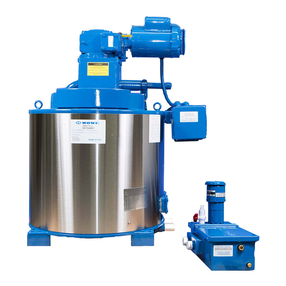
- Page 1 Ice Flaker Rapid Freeze ® Installation & Service Manual For Use with Remote Single Condensing Unit 4000-RL 6000-RL Phone: 1-773-235-0200 Howe Corporation Fax: 1-773-235-0269 1650 North Elston Avenue Website: www.howecorp.com Chicago, IL 60642-1585 Email: howeinfo@howecorp.com...
-
Page 3: Table Of Contents
ENGINEERING GUIDELINES .........................3 Location Requirements ................................3 Water Supply Requirements ..............................3 Drain Water Piping Requirements ............................4 Electrical Requirements ................................4 Refrigeration Requirements ..............................6 Piping Table..................................... 8 Refrigerant Pipework ................................8 Refrigerant Pipework Insulation Requirements ........................8 FIELD INSTALLATION ..........................9 Safety Information and Guidelines ............................ -
Page 4: Engineering Guidelines
Straight Reverse Osmosis (RO) treated water should never be supplied to the Ice Flaker. If installing the Ice Flaker with a Howe Ice Bin, ensure that the bin is adequately secured to RO system treated water is aggressive toward the floor so as to prevent the assembly from metals and plated surfaces. -
Page 5: Drain Water Piping Requirements
Generally, filtration of cold supply water is pipe drops should drain water through an recommended. Howe offers a complete line of indirect water connection with an “Air Gap”. replaceable core cartridge filter treatment Code authorities having jurisdiction may dictate systems designed to improve ice quality and other indirect water connection requirements. -
Page 7: Refrigeration Requirements
Refrigeration requirements and/or capacity will vary with temperatures outside these conditions. Howe Furnished Condensing Units Howe furnished condensing units are properly Field Furnished Condensing Units Howe is not responsible for the performance of sized for outdoor design ambient temperature field furnished condensing units. Howe and supply water temperature conditions. - Page 8 Figure 1...
-
Page 9: Piping Table
R-744 installations or thermal insulation intended for cold secondary refrigerant applications. applications. Howe recommends the use of hard drawn ACR Liquid lines should be covered with 1/2” thick type L tubing with refrigeration grade wrought and suction lines with 3/4” thick material. -
Page 10: Field Installation
Field Installation Ground Mounting Safety Information and Guidelines Concrete slab raised six inches above ground Only qualified service technicians should level provides a suitable base. Raising the base attempt to install, service, or maintain the Ice above ground level provides some protection Flaker. -
Page 11: Piping
Piping Leak Testing The Ice Flaker has been thoroughly cleaned and After all refrigerant connections are made, the dehydrated at the factory. However, foreign entire system must be leak tested. matter may enter the system by way of the The complete system should be pressurized to piping to the condensing unit. -
Page 12: Field Wiring
Field Wiring 4. Remove the wire jumper between the All field wiring must be in compliance with local terminals marked “A” and “B” in the and national codes. Use only copper Control Panel. conductors of the appropriate size. An electrical Control Panel is shipped loose with 5. -
Page 13: Evacuation
Evacuation Refrigerant Charging Instructions Do not use the refrigeration compressor to All Ice Flakers are shipped with a small holding evacuate the system. Do not start the charge of dry nitrogen. Ice flakers must be compressor while it is in a vacuum. evacuated before charging. -
Page 14: Installation Checklist
Installation Checklist 1. Has the ambient temperature been verified between 50°F – 100°F? (see Location Requirements p.3) 2. Has the incoming water temperature been verified between 45°F – 90°F? (see Water Supply Requirements p.3) 3. Has the water supply pressure been verified between 20 PSIG and 60 PSIG? (see Water Supply Requirements p.3) 4. -
Page 15: Start Up And Operation
Start Up and Operation Water Operation 1. Water Inlet Connection 5. Water Distribution Pan & Side Spouts 2. Float Valve 6. Sump Connections 3. Water Pump 7. Stop Valve 4. Water Regulating Valve 8. Drain Outlet... - Page 16 Adjust the water level by rotating the float end Water Inlet of the Float Valve. Rotate clockwise to raise the The supply water feed for the Ice Flaker must water level and counterclockwise to lower the be connected here. A shut-off valve should be water level.
- Page 17 Water Distribution Pan Water Regulating Valve The Water Distribution Pan circulates the water Adjust the water level in the Water Distribution fed from the Water Pump down the walls of the Pan by opening or closing the Water Regulating Evaporator. Valve located directly above the Water Sump.
-
Page 18: Refrigeration Operation
Refrigeration Operation *Piping insulation not shown 1. Evaporator Pressure Regulator (EPR) 5. TXV Sensing Bulb 2. Solenoid Valve 6. Evaporator 3. Sight Glass 7. Pressure Tap 4. Thermostatic Expansion Valve (TXV) - Page 19 Evaporator Pressure Setting Model Temperature R-404A R-507 4000-RL -5°F 28 PSI 30 PSI 6000-RL -5°F 28 PSI 30 PSI To increase the pressure setting, rotate Evaporator Pressure Regulator (EPR) clockwise. The EPR will hold the suction temperature at the proper level, allowing for minor To decrease the pressure setting, rotate adjustments to be made using the Thermostatic counter-clockwise.
- Page 20 Thermostatic Expansion Valve (TXV) Adjusting Refrigeration to the Ice Flaker Always adjust the EPR prior to adjusting the 1. Visually inspect the frost pattern on the TXV. freezing surface of the Evaporator. If the TXV is underfeeding, the top of the frost pattern will be a milky white color and the bottom will be clear, soft, and not harvest properly.
- Page 21 Solenoid Valve Low Pressure Control The Solenoid Valve controls the flow of liquid All Howe Condensing Units are supplied with a refrigerant to the Evaporator. separate Low Pressure Control for continuous pump down. The Solenoid Valve should energize immediately upon starting the Ice Flaker.
- Page 22 Field Capacity Check 8. Compare the number with the rated The Ice Flaker is a continuous production capacity of the Ice Flaker. Keep in mind machine and makes ice at a steady rate once temperatures outside the rated stabilized. conditions will have an effect on the A Capacity Check confirms the Ice Flaker and capacity.
-
Page 23: Electrical Operation
Electrical Operation 1. Motor Contactor (M1) 4. Fuses (FU1 & FU2) 2. Control Module (CM) 5. Water Pump Relay (R1) 3. Transformer (T1) 6. Level Control Relay (LC1) 1. Term 1: 24V Input Power 7. Term 7: Solenoid Valve Contact 2. - Page 24 Level Control Relay (LC1) This relay processes the signal from the Photo Control Module (CM) The control Module features eight wire Eyes. It shuts the Ice Flaker off when the Ice Bin terminals, two adjustable dials, and one is full to prevent damage caused by ice backing indicating light.
- Page 25 Off-Delay Setting Motor Overload Setting Under Normal Operation the Off-Delay Setting The proper adjustment of Motor Overload should be adjusted to run approximately 2 Setting will protect the Ice Flaker and help avoid minutes after the Solenoid Valve shuts off the nuisance service calls.
- Page 26 Photo Eyes (Level Control) Photo Eye Wiring...
- Page 27 Bin the Photo Eyes will be shipped loose and making ice. need to be properly mounted by the installing contractor. Please contact Howe for further When the infrared beam is blocked, both green information. LEDs will remain lit. However, the amber LED on the Receiver will go out.
-
Page 28: Mechanical Operation
Mechanical Operation 1. Ice Deflector 4. Speed Reducer 2. Ice Blade 5. Drive Motor 3. Squeegee... - Page 29 Ice Blade Ice Deflector The Ice Blade shatters the ice formed on the The Ice Deflector prevents ice from dropping Evaporator freezing surface as the Main Shaft into the water return trough. rotates. A properly installed Ice Deflector should have Ice harvesting problems are often caused by the top outer edge positioned outside of the ice improper refrigeration settings.
- Page 30 Squeegee Drive Motor and Speed Reducer The Squeegee wipes excess water from the The Drive Motor is attached to the Speed freezing surface so that the ice is dry upon Reducer by (4) mounting screws. There are no production. other screws or pins holding the Drive Motor in place.
- Page 31 Please contact Howe to receive the Sleeve Bearing Replacement Instructions for your model Ice Flaker. Howe is proud to offer our Factory Rebuild Program as an alternative to replacing parts such as the Sleeve Bearings in the field.
-
Page 32: Start-Up Checklist
Start-Up Checklist 1. Is the operating water level in the Water Sump correct? (see Float Valve p.15) 2. Is the operating water level in the Water Distribution Pan correct? (see Water Distribution Pan p.15) 3. Is the Stop Valve on Sump Drain connection closed? (see Stop Valve p.15) 4. -
Page 33: Maintenance
Maintenance Preventative Maintenance Schedule Page Every 3 Every 6 Every 12 Number Months Months Months Lubricate Sleeve Bearings • Ensure Float Valve is unclogged and • flowing freely Verify correct Sequence of Operation of • Photo Eye sensors Clean and Sanitize Ice Flaker •... -
Page 34: Cleaning Procedure
Cleaning Procedure To keep the evaporator in peak performance, the Ice Flaker should be cleaned every 6 months or more often if water conditions dictate. Only use cleaning solutions that are labeled as “Nickel-Safe”. 4. Close water supply at shut-off valve. 1. -
Page 35: Sanitizing Procedure
Sanitizing Procedure 1. Mix 16 oz. of household bleach with 2 gallons of warm water (90°F – 115°F). 2. Pour solution into the Water Sump to the normal operating level, then re- circulated the sanitizing solution for approximately 20 minutes by turning on Drive Motor and Water Pump. -
Page 36: Lubrication
Lubrication Speed Reducer Lubrication All speed reducers are to be filled with Mobil Glygoyle 460 Lubricant only. When adding or changing oil for any reason, it should be remembered that oils of various types are not compatible with Mobil Glygoyle 460. -
Page 37: Water Filtration
Water Filtration cause added wear on parts and can clog valves and impede flow. The purpose of water filtration is to keep the Ice Flaker clean and operating efficiently. The value to the user is reduced operating cost due to less maintenance, improved performance and a greater return on investment as result of extended asset life. - Page 38 Howe Water Filters Howe offers a complete line of water treatment systems designed to extend the life and performance of the Ice Flaker. Howe Water Filters inhibit the formation of scale and provides additional corrosion protection. They remove 95% of all dirt, rust, and sediment larger than 5 microns.
-
Page 39: Troubleshooting
Troubleshooting (Note: All wire colors are subject to change) Problem Possible Cause Possible Solution 1. Unplugged or defective Photo Eye(s). 1. Ensure Photo Eyes are properly and securely connected. Place a wire jumper between terminals labeled “Blue” and “Black” it the Control Panel. If Ice Flaker starts, Photo Eyes may be defective and need to be replaced. - Page 40 1. Ambient Temperature is too low. 1. If ambient temperature is below 50°F, relocate Ice Flaker to a warmer area. Ice accumulates on the ribs of Contact Howe about Low Ambient Kit. Bottom Casting 1. Motor Overload setting is too high.
- Page 41 4. Check that all drains are flowing freely and pitched away from Ice Bin. 5. Ice turnover is low and Ice Bin inventory 5. Use or discard ice within a reasonable time of producing it. Contact Howe about has become stale and clumped by lengthy Energy Saver Ice Production Management System.
-
Page 42: Appendix
Appendix Cut View... - Page 43 Wiring Diagram – 230/1/60 Power Ice Flaker with Howe Supplied Condensing Unit For other voltages or flakers not supplied with condensing units from Howe Corporation - please have a serial number and contact factory for the correct wiring diagram...
- Page 44 Wiring Diagram – Bohn 230/3/60 Air-Cooled Condensing Unit supplied by Howe For other voltages please have a serial number and contact Howe Corporation for the correct wiring diagram. If condensing unit was not supplied by Howe Corporation – contact condensing unit...
- Page 45 Wiring Diagram – Keep Rite 230/3/60 Air-Cooled Condensing Unit supplied by Howe For other voltages please have a serial number and contact Howe Corporation for the correct wiring diagram. If condensing unit was not supplied by Howe Corporation – contact condensing unit...
- Page 46 Installation & Service Manual For Use with Remote Single Condensing Unit (4000-RL & 6000-RL) Rev. Date: Feb-16...
- Page 47 Flake Ice Machine Cross-Section...
- Page 48 4000-RL, RLA, 6000-RL, Replacement parts for models RLR, 20E, RLA, RLR, TABLE 2 listed to right 21ES, EFS, 30E, 31ES, EFS, ESS Part Numbers Item No. Part Description E20J4 Insulated Lug Spacers (8) Main Shaft E20D2 E30D4 E20E2 Ice Blade 8 ½” L, 12 ½“ L, 20 ½“ L E30E3 Nuts, bolts &...
- Page 49 Water distribution bottom spout / 37 & 38 E20H38 fitting Water Distribution pan assembly (includes dist. Tubes/fittings) (Plastic E20H44 Pan / Tubes) Water Distribution pan assembly (includes dist. Tubes/fittings) E30H9 (Aluminum Pan / Copper Tubes) E30H9 Seawater Distribution Pan E10H15 Seawater Distribution Pan Cover Water distribution side spout &...
- Page 50 Replacement Water pump Assembly w/mounting plate, ball valve, tubing, with E10Q5-P Molex Plug 230/1/50-60 (April 2006 and OLDER) Metal cover E10H61 Water sump assembly for RL Models E30H7 Water sump assembly for RLE Models Drain Lines for Sump Water pump - seawater 115-230/1/50- E20Q5 Drive motor 115-230/1/60, 1/3 HP, W/ Molex plug.
- Page 51 To help determinate which water float valve & water pump to use with which flake ice machine Use the following tables: pumps with -P / 2000 & 3000 "RL" Models use E10Q5 pump Water Pumps: Replacement Water Pumps for Freshwater Flake Ice Flaker Manufacture Date Machines Start Date End Date...
- Page 52 Control Panel Parts - F5U4 & E10U45 - Installed on RLE Models Control board, 24VAC. E20T48 Overload reset button (N.O.) E20T23 Snap-in On-off rocker switch E20T24 24 Volt control transformer E20T31 3-Pole relay for motor contactor, (24 volt coil) F5T2 3-Pole relay mounting base 5V013 Control Panel Parts - E20T40-RL &...
- Page 53 Neon Indicating Lights Green 230VAC (compressor run light - SCA control LGX-2 panel) Amber 230VAC (low suction pressure pump down LAN-2 light - SCA control panel) Red 230VAC (low oil pressure& high discharge LRN-2 pressure light - SCA control panel) Green 24VAC (flaker run light - RL &...
- Page 54 Miscellaneous USDA bearing lubricant E20K6 Ice machine nickel safe cleaner - 16oz bottle E10V1 Ice machine sanitizer - 16oz bottle E10V31 Clock timer retrofit kit E20T35-KT Knob for clock timer E20T107 Clock timer E20T35-1 Wind up timer E20T35-2 Low water float switch for 4000-RL flakers E10H36-KT Replacement float switch E10H36...
Need help?
Do you have a question about the Rapid Freeze 4000-RL and is the answer not in the manual?
Questions and answers