Acer Aspire 4315 Service Manual
Hide thumbs
Also See for Aspire 4315:
- User manual (106 pages) ,
- Manuel d'utilisation (114 pages) ,
- Guía del usuario (111 pages)

Subscribe to Our Youtube Channel
Related Manuals for Acer Aspire 4315


Summary of Contents for Acer Aspire 4315
- Page 1 Acer Aspire 4715Z/4315 Service Guide Service guide files and updates are available on the ACER/CSD web; for more information, please refer to http://csd.acer.com.tw PRINTED IN TAIWAN...
-
Page 2: Revision History
Revision History Please refer to the table below for the updates made on Travelmate 4715Z/4315 service guide. Date Chapter Updates... - Page 3 Copyright Copyright © 2007 by Acer Incorporated. All rights reserved. No part of this publication may be reproduced, transmitted, transcribed, stored in a retrieval system, or translated into any language or computer language, in any form or by any means, electronic, mechanical, magnetic, optical, chemical, manual or otherwise, without...
- Page 4 Any Acer Incorporated software described in this manual is sold or licensed "as is". Should the programs prove defective following their purchase, the buyer (and not Acer Incorporated, its distributor, or its dealer) assumes the entire cost of all necessary servicing, repair, and any incidental or consequential damages resulting from any defect in the software.
- Page 5 Conventions The following conventions are used in this manual: SCREEN MESSAGES NOTE WARNING CAUTION IMPORTANT Denotes actual messages that appear on screen. Gives bits and pieces of additional information related to the current topic. Alerts you to any damage that might result from doing or not doing specific actions.
- Page 6 DIFFERENT part number code to those given in the FRU list of this printed Service Guide. You MUST use the list provided by your regional Acer office to order FRU parts for repair and service of customer machines.
-
Page 7: Table Of Contents
Using the System Utilities Acer Empowering Technology Empowering Technology Password Acer eNet Management Acer ePower Management Acer ePresentation Management Acer eDataSecurity Management (for selected models) Acer eLock Management Acer eRecovery Management Acer eSettings Management Windows Mobility Center Acer GridVista (dual-display compatible) - Page 8 External Module Disassembly Process External Modules Disassembly Flowchart Removing the Battery Pack Removing the Express Dummy Card Removing the Lower Cover Removing the DIMM Removing the WLAN Board Module Removing the Hard Disk Drive Module Removing the Optical Drive Module Main Unit Disassembly Process Main Unit Disassembly Flowchart Removing the CPU Heatsink Module...
- Page 9 FRU (Field Replaceable Unit) List 109 Aspire 4715Z/4315 Exploded Diagram Aspire 4715Z FRU List (No: LX.AL40C.013) Aspire 4715Z FRU List (No: LX.AL10Y.001/003/015) Aspire 4315 FRU List (No: LX.AKZ0C.007) Model Definition and Configuration Aspire 4715Z/4315 Test Compatible Components Microsoft® Windows® Vista™ Compatibility Test...
-
Page 11: System Specification
Display and Graphics 14.1" WXGA high brightness (200-nits) Acer CrystalBrite response time, supporting simultaneous multi-window viewing via Acer GridVista Mobile Intel GL960 Express Chipset with integrated 3D graphics, featuring Intel Graphics Media Accelerator (GMA) X3100 with up to 358 MB of Intel Dynamic Video Memory Technology 4.0 (8 MB of... -
Page 12: Dimensions And Weight
Communication Integrated Acer Crystal Eye webcam supporting Acer PrimaLite ™ WLAN: Acer InviLink technology LAN: Fast Ethernet; Wake-on-LAN ready Modem: 56K ITU V.92 with PTT approval; Wake-on-Ring ready I/O Interface ™ ExpressCard /54 slot Three USB 2.0 ports External display (VGA) port... -
Page 13: Your Acer Notebook Tour
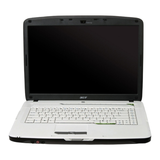
Your Acer Notebook Tour After knowing the computer features, let us show you around the new Aspire computer. Front View Item Microphone Display screen Power button Status indicators Empowering key Easy-launch buttons Palmrest Status indicators Click buttons (left and right) -
Page 14: Closed Front View
Closed Front View Icon Item Latch Microphone jack Headphones/speaker/ line-out jack Left View Icon Item Kensington lock slot External display (VGA) port Modem (RJ-11) port Ethernet (RJ-45) port S-video/TV-out (NTSC/PAL) port USB 2.0 port ExpressCard/54 slot Description Locks and releases the lid. Accepts inputs from external microphones. -
Page 15: Right View
Right View Icon Item Optical drive Optical disk access indicator Optical drive eject button Emergency eject hole USB 2.0 ports DC-in jack Rear Panel Item Ventilation slots Chapter 1 Description Internal optical drive; accepts CDs or DVDs. Lights up when the optical drive is active. Ejects the optical disk from the drive. -
Page 16: Bottom Panel
Bottom Panel Icon Item Battery bay Battery release latch Battery lock Memory compartment Hard disk bay Ventilation slots and cooling fan Description Houses the computer's battery pack. Releases the battery for removal. Locks the battery in position. Houses the computer's main memory. Houses the computer’s hard disk (secured with screws) Enable the computer to stay cool, even after prolonged use. -
Page 17: Indicators
Indicators The computer has four easy-to-read status indicators: The front panel indicators are visible even when the computer cover is closed up. Icon Function Num lock Caps lock Power Battery NOTE: Battery LED status during charging: • Amber: Charging. • Green: Charging complete. Chapter 1 Description Indicates when the hard disk drive is active. -
Page 18: Easy-Launch Buttons
> and one user-programmable button. Press < > to run the Acer Empowering Technology. The mail and Web browser buttons are pre-set to email and Internet programs, but can be reset by users. To set the Web browser, mail and programmable buttons, run the Acer Launch Manager. -
Page 19: Touchpad
Touchpad The built-in seamless touchpad is a pointing device that senses movement on its surface. This means the cursor responds as you move your finger across the surface of the touchpad. The central location on the palmrest provides optimum comfort and support. Touchpad Basics The following teaches you how to use the touchpad: Move your finger across the touchpad (2) to move the cursor. - Page 20 Function Left Button (1) Execute Click twice quickly. Select Click once. Drag Click and hold, then use finger to drag the cursor on the touchpad Access context menu Scroll NOTE: When using the touchpad, keep it - and your fingers - dry and clean. The touchpad is sensitive to finger movement;...
-
Page 21: Using The Keyboard
Using the Keyboard The keyboard has full-sized keys and an embedded keypad, separate cursor keys, two Windows keys and twelve function keys, and two special keys. Lock Keys and Embedded Numeric Keypad The keyboard has three lock keys which you can toggle on and off. Lock Key Description Caps Lock... -
Page 22: Windows Keys
Windows Keys The keyboard has two keys that perform Windows-specific functions. Icon Windows key Application key Description Pressed alone, this key has the same effect as clicking on the Windows Start button; it launches the Start menu. It can also be used with other keys to provide a variety of functions: <... -
Page 23: Hotkeys
> Chapter 1 Function Description Hot key help Displays help on hot keys. Acer eSettings Launches the Acer eSettings in Acer eManager. Acer ePower Launches the Acer ePowerManagement in Acer Management eManager. Sleep Puts the computer in Sleep mode. Display toggle Switches display output between the display screen, external monitor (if connected) and both. -
Page 24: Special Keys
Special Keys You can locate the Euro symbol and the US dollar sign at the upper-center and/or bottom-right of your keyboard. The Euro symbol Open a text editor or word processor. Either press < > at the bottom-right of the keyboard, or hold <Alt Gr> and then press the <5> key at the upper-center of the keyboard. -
Page 25: Using The System Utilities
NOTE: Models shipped with Windows Vista Starter Edition only support Acer eRecovery Management. The Empowering Technology toolbar makes it easy for you to access frequently used functions and manage your new Acer system. Displayed by default in the upper half of your screen, it provides access to the following utilities: Acer eNet Management hooks up to location-based networks intelligently. -
Page 26: Acer Enet Management
To access this utility, select "Acer eNet Management" from the Empowering Technology toolbar or run the program from the Acer Empowering Technology program group in Start menu. You can also set Acer eNet Management to start automatically when you boot up your PC. - Page 27 Acer eNet Management can save network settings for a location to a profile, and automatically switch to the appropriate profile when you move from one location to another. Settings stored include network connection settings (IP and DNS settings, wireless AP details, etc.), as well as default printer settings. Security and safety concerns mean that Acer eNet Management does not store username and password information.
-
Page 28: Acer Epower Management
To access this utility, select "Acer ePower Management" from the Empowering Technology toolbar, run the program from the Acer Empowering Technology program group in Start menu, or right-click the Windows power icon in the system tray and select "Acer ePower Management". -
Page 29: Battery Status
Battery status For real-time battery life estimates based on current usage, refer to the panel in the upper half of the window. Click the to view estimated battery life in sleep and hibernate modes. Chapter 1... -
Page 30: Acer Epresentation Management
Acer ePresentation Management Acer ePresentation Management lets you project your computer's display to an external display device or projector using the hotkey: <Fn> + <F5>. If auto-detection hardware is implemented in the system and the external display supports it, your system display will be automatically switched out when an external display is connected to the system. -
Page 31: Acer Edatasecurity Management (For Selected Models)
Acer eDataSecurity Management Acer eDataSecurity Management is an encryption utility that protects your files from being accessed by unauthorized persons. It is conveniently integrated with Windows Explorer as a shell extension for quick data encryption/decryption and also supports on-the-fly file encryption for Lotus Notes and Microsoft Outlook. -
Page 32: Acer Elock Management
Acer eLock Management Acer eLock Management is simple yet effective utility that allows you to lock removable storage, optical and floppy drive devices to ensure that data can't be stolen while your system is unattended. Removable Storage Devices — includes USB disk drives, USB pen drives, USB flash drives, USB MP3 drives, USB memory card readers, IEEE 1394 disk drives, and any other removable storage devices that can be mounted as a file system when plugged into the system. -
Page 33: Acer Erecovery Management
From previously-created CD/DVD Reinstall applications/drivers NOTE: If your computer did not come with a Recovery CD or System CD, please use Acer eRecovery Management's "System backup to optical disc" feature to burn a backup image to CD or DVD. To... -
Page 34: Acer Esettings Management
Acer eSettings Management Acer eSettings Management allows you to inspect hardware specifications, set BIOS passwords and modify boot options. Acer eSettings Management also: Provides a simple graphical user interface for navigation. Prints and saves hardware specifications. Lets you set an asset tag for your system. -
Page 35: Windows Mobility Center
The Windows Mobility Center collects key mobile-related system settings in one easy-to-find place, so you can quickly configure your Acer system to fit the situation as you change locations, networks or activities. Settings include display brightness, power plan, volume, wireless networking on/off, external display settings, display orientation and synchronization status. -
Page 36: Acer Gridvista (Dual-Display Compatible)
Acer GridVista is a handy utility that offers four pre-defined display settings so you can view multiple windows on the same screen. To access this function, please go to Start, All Programs and click on Acer GridVista. You may choose any one of the four display settings indicated below: Double (vertical), Triple (primary at left), Triple (primary at right), or Quad Acer Gridvista is dual-display compatible, allowing two displays to be partitioned independently. -
Page 37: Launch Manager
Launch Manager Launch Manager allows you to set the four easy-launch buttons located above the keyboard. You can access the Launch Manager by clicking on Start, All Programs, and then Launch Manager to start the application. Norton Internet Security Norton Internet Security is an anti-virus utility that can protect against viruses, keeping your data safe and secure. -
Page 38: Hardware Specifications And Configurations
Hardware Specifications and Configurations Processor Item Specification CPU type Intel Pentium Dual-Core T2310 Mobile Processor Clock 1.46 GHz Speeds L2 Cache 1 MB Front Side 533 MHz System Board Major Chips Item Specification System core logic Intel GL960 Express chipset + Intel ICH8-M chipset HDD controller Intel ICH8-M chipset Memory controller... - Page 39 Hard Disk Drive Interface Item Specification Buffer size (MB) 8.192 Media transfer rate (Mbytes/s, max) Interface transfer rate (Mbytes/s, max) Voltage 5V(DC) +/- 5% tolerance BIOS Item BIOS vendor BIOS Version Supported protocols System Memory Item Specification Memory controller Intel GL960 Express chipset DIMM socket number 2 sockets Supports maximum...
- Page 40 Microsoft DirectX 9 and PCI Express 1280 x 800 128 MB Specification Realtek ALC268 Codec chipset Two built-in Acer 3D Sonic stereo speakers, Supports high definition audio, Built-in microphone, MS-sound compatible Specification Intel ICH8-M chipset Type-II Specification...
- Page 41 Keyboard and Input Devices Item Keyboard controller Vendor Model name Features Combo Drive Interface Item Vendor Model name Drive type Data transfer rate Buffer Memory Interface Applicable disc format Power supply Chapter 1 Specification Winbond WPC8763L chipset Darfon NSK-H3V1D, NSK-H3V0U 5-degree curve, 88-/89-/93- key, inverted “T”...
- Page 42 DVD Drive Interface Item Vendor Model name Drive type Data transfer rate Buffer Memory Interface Applicable disc format Power supply Specification Sony Pioneer AD-7560A DVR-K17RS Internal Slim DVD/CD writer Write: Write: • CD-R: 24X • CD-R: 24X • CD-RW: 24X •...
- Page 43 Battery Item Vendor Battery Type Pack capacity Item Vendor Model name Screen diagonal (mm) Display resolution (pixels) Aspect ratio Active area (mm) Pixel pitch (mm) Mode Number of colors Color saturation (NTSC%) Brightness (nits) Contrast ratio Response time (optical rise time + fall time) (msec) Power consumption (watt) Supply voltage (v)
- Page 44 AC Adapter Item Specification Vendor Delta Model Name SADP-65KB DFA Output rating 19 V/3.42 A, 65 W Input (Vac) 90 ~ 270 System Power Management ACPI mode Lite-On Lishin PA-1650-02 AC SLS0335A19A54 19 V/3.42 A, 65 W 19 V/3.42 A, 65 W 100 ~ 240 90 ~ 265 Power Management...
-
Page 45: System Utilities
System Utilities BIOS Setup Utility The BIOS Setup Utility is a hardware configuration program built into your system’s BIOS (Basic Input/Output System). Since most systems are already properly configured and optimized, there is no need to run this utility. The BIOS setup utility stores basic settings for your system. You will need to run this utility if you encounter configuration problems. -
Page 46: Information Menu
Information Menu Parameter Description CPU Type Type of processor currently installed in the system. CPU Speed Speed of the processor currently installed in the system. IDE0 Model Name Model name of HDD installed on the primary IDE channel. IDE0 Serial Number Serial number of HDD installed on the primary IDE channel. -
Page 47: Main Menu
Main Menu Parameter Description System Time Set the system time following the hour-minute-second format. System Date Set the date following the weekday-month-day-year format. System Memory Total size of system memory detected during POST. Extended Memory Total size of extended memory during POST. Video Memory Total size of VGA memory. -
Page 48: Security Menu
Security Menu Parameter Supervisor Password Is User Password Is HDD Password Is Set Supervisor Password Set User Password Set HDD Password Password on Boot NOTE: Refer to the “Removing a System Password” on page 39 for more information on how to remove a password. -
Page 49: Clearing The Supervisor Or User Password
Setting a System Password Use the up/down keys to select a password parameter, then press Enter. A Password box appears. Type a password then press Enter. The password may consist of up to six alphanumeric characters (A-Z, a-z, 0-9). Retype the password to verify the first entry then press Enter again. You will be prompted to save the new password. -
Page 50: Operation Description
Locate the hardware gap. The gap is highlighted in the illustration below. Hardware gap Default setting Open (Normal) Using an electrical conductivity tool, short the two contacts on the hardware gap together. While resting the tool on the two contacts, plug one end of the AC adapter into the DC-in jack and plug one end to an electrical outlet. -
Page 51: Boot Menu
Boot Menu This menu allows you to set the drive priority during system boot-up. The system will attempt to boot from the first device on the list. If the first device is not available, it will continue down the list until it reaches an available device. -
Page 52: Exit Menu
Exit Menu Parameter Description Exit Saving Changes Save changes made and close the BIOS setup. Exit Discarding Changes Discards changes made and close the BIOS setup. Load Setup Defaults Loads the default settings for all BIOS setup parameters. Setup Defaults are quite demanding in terms of resources consumption. -
Page 53: Bios Recovery
BIOS Recovery If BIOS flash procedure fails in your system, perform a BIOS recovery procedure by using the crisis recovery diskette. During this procedure, the system will force BIOS to load and execute a special BIOS block (also called boot block) to restore the BIOS code from the crisis recovery diskette. Note the following when restoring the BIOS settings: Use the <Fn>... - Page 54 Chapter 2...
-
Page 55: Machine Disassembly And Replacement
Machine Disassembly and Replacement This chapter contains step-by-step procedures on how to disassemble the notebook computer for maintenance and troubleshooting. Disassembly Requirements To disassemble the computer, you need the following tools: Wrist grounding strap and conductive mat for preventing electrostatic discharge Flat-blade screwdriver Philips screwdriver Hex screwdriver... -
Page 56: General Information
General Information Pre-disassembly Instructions Before proceeding with the disassembly procedure, make sure that you do the following: Turn off the power to the system and all peripherals. Unplug the AC adapter and all power and signal cables from the system. Place the system on a flat, stable surface. -
Page 57: Disassembly Process
Disassembly Process The disassembly process is divided into the following stages: External module disassembly Main unit disassembly LCD module disassembly The flowcharts provided in the succeeding disassembly sections illustrate the entire disassembly sequence. Observe the order of the sequence to avoid damage to any of the hardware components. For example, if you want to remove the mainboard, you must first remove the keyboard, then disassemble the inside assembly frame in that order. -
Page 58: External Module Disassembly Process
External Module Disassembly Process External Modules Disassembly Flowchart The flowchart below gives you a graphic representation on the entire disassembly sequence and instructs you on the components that need to be removed during servicing. For example, if you want to remove the mainboard, you must first remove the keyboard, then disassemble the inside assembly frame in that order. -
Page 59: Removing The Battery Pack
Removing the Battery Pack Turn base unit over. Slide the battery lock/unlock latch to the unlock position. Slide and hold the battery release latch to the release position, then remove the battery from the main unit. Removing the Express Dummy Card See “Removing the Battery Pack”... -
Page 60: Removing The Lower Cover
Remove the card from the slot. Removing the Lower Cover See “Removing the Battery Pack” on page 49. Turn the base unit over, then loosen the eight screws on the lower cover. Use a plastic flat-blade screwdriver to pry open the lower cover. Chapter 3... -
Page 61: Removing The Dimm
Remove the lower cover from the lower case. Removing the DIMM See “Removing the Battery Pack” on page 49. See “Removing the Lower Cover” on page 50. Push out the latches on both sides of the DIMM socket to release the DIMM. Remove the DIMM module. -
Page 62: Removing The Wlan Board Module
Removing the WLAN Board Module See “Removing the Battery Pack” on page 49. See “Removing the Lower Cover” on page 50. Disconnect the antenna cable from the WLAN board, then move the antenna away from the board. Remove the two screws (A) on the WLAN board to release the WLAN board. Step Detach the WLAN board from the WLAN socket. -
Page 63: Removing The Hard Disk Drive Module
Removing the Hard Disk Drive Module See “Removing the Battery Pack” on page 49. See “Removing the Lower Cover” on page 50. Remove the screw (A) securing the HDD assembly to the unit. Step Pull the HDD module out by pulling on the mylar attached to it (1), gently slide-out the HDD module from its bay (2). -
Page 64: Removing The Optical Drive Module
Remove the hard disk drive. Removing the Optical Drive Module See “Removing the Battery Pack” on page 49. See “Removing the Lower Cover” on page 50. Remove the screw (C) on the bottom side of the unit, as shown. Step Using the flat-blade screwdriver, press the end of the module forward, then slide out the optical drive module from the main unit. - Page 65 Remove the two screws (E) securing the optical bracket and remove the locker bracket from the optical disk drive module. Step Size (Quantity) Color Torque M2 x L2.5 (2) Silver 1.6 kgf-cm Chapter 3...
-
Page 66: Main Unit Disassembly Process
Main Unit Disassembly Process Main Unit Disassembly Flowchart Chapter 3... -
Page 67: Removing The Cpu Heatsink Module
Screw List Removing the CPU Heatsink Module See “Removing the Battery Pack” on page 49. See “Removing the Lower Cover” on page 50. Detach the heatsink cable from the mainboard. Loosen the four spring-loaded screws on the heatsink in the order shown. Chapter 3 Screw Size M2 x L4... -
Page 68: Removing The Cpu
Remove the heatsink module. Removing the CPU See “Removing the Battery Pack” on page 49. See “Removing the Lower Cover” on page 50. See “Removing the CPU Heatsink Module” on page 57. Using a flat-blade screwdriver, turn the CPU socket latch to the unlock position by aligning the latch to the unlock symbol, then remove the CPU. -
Page 69: Removing The Keyboard
Removing the Keyboard See “Removing the Battery Pack” on page 49. Press the plastic flat-blade screwdriver to the notches, shown below, to disengage the keyboard from the main unit. Carefully pry up and out the keyboard and turn it over. Disconnect the keyboard cable from the mainboard to remove the keyboard. -
Page 70: Removing The Middle Cover
Removing the Middle Cover See “Removing the Battery Pack” on page 49. See “Removing the Keyboard” on page 59. Open the LCD screen all the way to facilitate the easy removal of the middle cover. Carefully insert the flat-blade screwdriver between the middle cover and lower case and gently pry up the middle cover. -
Page 71: Removing The Lcd Module
Removing the LCD Module See “Removing the Battery Pack” on page 49. See “Removing the Lower Cover” on page 50. See “Removing the WLAN Board Module” on page 52. See “Removing the Keyboard” on page 59. See “Removing the Middle Cover” on page 60. Disconnect the microphone cable from the mainboard. - Page 72 Turn the system over and remove the two screws (F) from the base of the unit. Step 10. Remove the two screws (F) from the left and right hinge of the LCD module. Step 11. Carefully remove the LCD module from the base unit. NOTE: Make sure the cables are routed well before connecting the cables back to the unit.
-
Page 73: Separating The Upper Case From The Lower Case
Separating the Upper Case from the Lower Case See “Removing the Battery Pack” on page 49. See “Removing the Express Dummy Card” on page 49. See “Removing the Lower Cover” on page 50. See “Removing the DIMM” on page 51. See “Removing the WLAN Board Module”... - Page 74 15. Detach the touchpad cable from the mainboard. 16. Turn the system over and remove the eleven screws (C, D) on the lower case. Step 1~10 17. Gently detach the upper case from the lower case. Size (Quantity) M2 x L6 (10) M2 x L8 (1) Color Torque...
-
Page 75: Removing The Speaker Modules
Removing the Speaker Modules See “Removing the Battery Pack” on page 49. See “Removing the Express Dummy Card” on page 49. See “Removing the Lower Cover” on page 50. See “Removing the DIMM” on page 51. See “Removing the WLAN Board Module” on page 52. See “Removing the Hard Disk Drive Module”... -
Page 76: Removing The Launch Board Bracket
Removing the Launch Board Bracket See “Removing the Battery Pack” on page 49. See “Removing the Express Dummy Card” on page 49. See “Removing the Lower Cover” on page 50. See “Removing the DIMM” on page 51. See “Removing the WLAN Board Module” on page 52. See “Removing the Hard Disk Drive Module”... -
Page 77: Removing The Touchpad Board Module
Removing the Touchpad Board Module See “Removing the Battery Pack” on page 49. See “Removing the Express Dummy Card” on page 49. See “Removing the Lower Cover” on page 50. See “Removing the DIMM” on page 51. See “Removing the WLAN Board Module” on page 52. See “Removing the Hard Disk Drive Module”... -
Page 78: Removing The Audio Board
16. Carefully insert the flat-bladescrewdriver under the side of the touchpad board and gently pry up the board. 17. Continue prying the board until it releases from the upper case, then remove the board. Removing the Audio Board See “Removing the Battery Pack” on page 49. See “Removing the Express Dummy Card”... - Page 79 14. Disconnect the audio board cable from the mainboard. 15. Remove the two screws (A) on the audio board. Step Size (Quantity) Color Torque M2 x L4 (2) Black 1.6 kgf-cm 16. Remove the audio board. Chapter 3...
-
Page 80: Removing The Usb Board
Removing the USB Board See “Removing the Battery Pack” on page 49. See “Removing the Express Dummy Card” on page 49. See “Removing the Lower Cover” on page 50. See “Removing the DIMM” on page 51. See “Removing the WLAN Board Module” on page 52. See “Removing the Hard Disk Drive Module”... -
Page 81: Removing The Mainboard
16. Remove the screw (A) on the USB board. Step 17. Remove the USB board. Removing the Mainboard See “Removing the Battery Pack” on page 49. See “Removing the Express Dummy Card” on page 49. See “Removing the Lower Cover” on page 50. See “Removing the DIMM”... -
Page 82: Removing The Modem Board
16. Remove the screw (A) holding the mainboard to the lower case. Step 17. Carefully detach the mainboard from the lower case. Removing the Modem Board See “Removing the Battery Pack” on page 49. See “Removing the Express Dummy Card” on page 49. See “Removing the Lower Cover”... - Page 83 17. Disconnect the modem cable from the mainboard. 18. Detach the masking tape from the mainboard. 19. Remove the two screws (I) on the modem board. Step Size (Quantity) Color Torque Black 1.6 kgf-cm Chapter 3...
-
Page 84: Removing The Rtc Battery
20. Detach the modem board from the mainboard. Removing the RTC Battery See “Removing the Battery Pack” on page 49. See “Removing the Express Dummy Card” on page 49. See “Removing the Lower Cover” on page 50. See “Removing the DIMM” on page 51. See “Removing the WLAN Board Module”... - Page 85 18. Carefully detach the RTC battery from the SD card slot. Chapter 3...
-
Page 86: Lcd Module Disassembly Process
LCD Module Disassembly Process LCD Module Disassembly Flowchart Main Screw List Item Screw Size Part No. M2.5 x L6 86.00E33.736 M2 x L3 86.00C07.220 Chapter 3... -
Page 87: Removing The Lcd Bezel
Removing the LCD Bezel See “Removing the Battery Pack” on page 49. See “Removing the Lower Cover” on page 50. See “Removing the DIMM” on page 51. See “Removing the WLAN Board Module” on page 52. See “Removing the Hard Disk Drive Module” on page 53. See “Removing the Optical Drive Module”... -
Page 88: Removing The Camera Board
14. Carefully pry open the LCD bezel and remove the bezel from the LCD module. Removing the Camera Board See “Removing the Battery Pack” on page 49. See “Removing the Lower Cover” on page 50. See “Removing the DIMM” on page 51. See “Removing the WLAN Board Module”... -
Page 89: Removing The Inverter Board
14. Remove the camera board. Removing the Inverter Board See “Removing the Battery Pack” on page 49. See “Removing the Lower Cover” on page 50. See “Removing the DIMM” on page 51. See “Removing the WLAN Board Module” on page 52. See “Removing the Hard Disk Drive Module”... -
Page 90: Removing The Lcd With Brackets
15. Turn the inverter board over. 16. Disconnect the 2P cable from the inverter board, then disconnect the inverter board cable from its connector. 17. Remove the inverter board. Removing the LCD with Brackets See “Removing the Battery Pack” on page 49. See “Removing the Lower Cover”... - Page 91 15. Remove the two screws (G) securing the left and right LCD brackets to the LCD back cover. Step Size (Quantity) Color Torque M2.5 x L6 (2) Silver 2.5 kgf-cm 16. Detach the LCD with the brackets from the back cover, then turn it over. 17.
- Page 92 18. Detach the acetic tapes holding the FPC cable to the edge of the LCD panel. 19. Detach the acetic tape holding the camera cable to the LCD panel. 20. Detach the acetic tape securing the FPC connector, then .disconnect the FPC cable from the LCD panel. Chapter 3...
-
Page 93: Removing The Lcd Brackets
Removing the LCD Brackets See “Removing the Battery Pack” on page 49. See “Removing the Lower Cover” on page 50. See “Removing the DIMM” on page 51. See “Removing the WLAN Board Module” on page 52. See “Removing the Hard Disk Drive Module” on page 53. See “Removing the Optical Drive Module”... -
Page 94: Removing The Antenna
14. See “Removing the Inverter Board” on page 79. 15. See “Removing the LCD with Brackets” on page 80. 16. See “Removing the LCD Brackets” on page 83. 17. Remove the two screws (G) securing the left and right LCD module hinges. Step 18. -
Page 95: Removing The Microphone
16. Detach the gasket tape holding the antenna in place, remove the antenna bracket, then carefully remove the antenna. Removing the Microphone See “Removing the Battery Pack” on page 49. See “Removing the Lower Cover” on page 50. See “Removing the DIMM” on page 51. See “Removing the WLAN Board Module”... - Page 96 13. Carefully detach the masking tape and remove the microphone cable from underneath the adhesive aluminum foil. 14. Remove the microphone. Chapter 3...
-
Page 97: Troubleshooting
Troubleshooting Use the following procedure as a guide for computer problems. NOTE: The diagnostic tests are intended to test only Acer products. Non-Acer products, prototype cards, or modified options can give false errors and invalid system responses. Obtain the failing symptoms in as much detail as possible. -
Page 98: System Check Procedures
System Check Procedures External CD/DVD-ROM Drive Check Perform the following procedures to isolate the possible problem a controller, drive, or CD-ROM. NOTE: Make sure that the CD-ROM does not have any label attached to it. The label may damage the drive or cause drive failure. -
Page 99: Power System Check
Power System Check Do the following: Remove the battery pack. Connect the power adapter and check the power supply. Disconnect the power adapter and install the battery pack; then check that power supply. If you suspect a power problem, see the appropriate power supply check in the following list: “Check the Power Adapter”... -
Page 100: Touchpad Check
Touchpad Check If the touchpad doesn’t work, do the following procedures in sequence to correct the problem. Do not replace a non-defective FRU: After rebooting, run Tracking Pad PS2 Mode Driver. For example Syn touch driver. Run utility with the PS/2 mouse function and check if the mouse is working. If the PS/2 mouse does not work, then click if the main board to switch board FPC is connected properly. -
Page 101: Power-On Self-Test (Post) Error Message
Power-On Self-Test (POST) Error Message The POST error message index lists the error message and their possible causes. NOTE: Perform the FRU replacement or actions in the sequence shown in FRU/Action column, if the FRU replacement does not solve the problem, put the original part back in the computer. Do not replace a non-defective FRU. -
Page 102: Index Of Error Messages
Index of Error Messages Error Message List Error Messages Stuck Key System CMOS checksum bad - Default configuration used Real time clock error Previous boot incomplete - Default configuration used Invalid System Configuration Data Operating system not found Power-on indicator turns off and LCD is blank. - Page 103 Error Message List Error Messages No beep, power-on indicator turns off and LCD is blank. No beep, power-on indicator turns on and LCD is blank. No beep, power-on indicator turns on and LCD is blank. But you can see POST on an external CRT.
-
Page 104: Phoenix Bios Beep Codes
Phoenix BIOS Beep Codes Code Beeps 1-2-2-3 1-3-1-1 1-3-1-3 1-3-4-1 1-3-4-3 1-4-1-1 POST Routine Description Verify Real Mode Disable Non-Maskable Interrupt (NMI) Get CPU type Initialize system hardware Initialize chipset with initial POST values Set IN POST flag Initialize CPU registers Enable CPU cache Initialize caches to initial POST values Initialize I/O component... - Page 105 Code Beeps 2-1-2-3 2-2-3-1 Chapter 4 POST Routine Description Check ROM copyright notice Check video configuration against CMOS Initialize PCI bus and devices Initialize all video adapters in system QuietBoot start (optional) Shadow video BIOS ROM Display BIOS copyright notice Display CPU type and speed Initialize EISA board Test keyboard...
- Page 106 Code Beeps POST Routine Description Initialize Extended BIOS Data Area Test and initialize PS/2 mouse Initialize floppy controller Determine number of ATA drives (optional) Initialize hard-disk controllers Initialize local-bus hard-disk controllers Jump to UserPatch2 Build MPTABLE for multi-processor boards Install CD-ROM for boot Clear huge ES segment register Fixup Multiprocessor table Search for option ROMs.
-
Page 107: Bios Beep Codes For Boot Block In Flash Rom
Code Beeps * If the BIOS detects error 2C, 2E, or 3O (base 512K RAM error), it displays an additional word-bitmap (xxxx) indicating the address line or bits that failed. For example, "2C 0002" means address line 1 (bit one set) has failed. "2E 1020" means data bits 12 and 5 (bits 12 and 5 set) have failed in the lower 16 bits. -
Page 108: Index Of Symptom-To-Fru Error Message
Index of Symptom-to-FRU Error Message LCD-Related Symptoms Symptom / Error LCD backlight doesn't work LCD is too dark LCD brightness cannot be adjusted LCD contrast cannot be adjusted Unreadable LCD screen Missing pels in characters Abnormal screen Wrong color displayed LCD has extra horizontal or vertical lines displayed. - Page 109 Power-Related Symptoms Symptom / Error The system doesn’t power-off. Battery can’t be charged PCMCIA-Related Symptoms Symptom / Error System cannot detect the PC Card (PCMCIA) PCMCIA slot pin is damaged. Memory-Related Symptoms Symptom / Error Memory count (size) appears different from actual size.
- Page 110 Power Management-Related Symptoms Symptom / Error The system doesn't resume from hibernation mode. The system doesn't resume from standby mode after opening the LCD. Battery fuel gauge in Windows doesn’t go higher than 90%. System hangs intermittently. Peripheral-Related Symptoms Symptom / Error System configuration does not match the installed devices.
- Page 111 Modem-Related Symptoms Symptom / Error Internal modem does not work correctly. NOTE: If you cannot find a symptom or an error in this list and the problem remains, see “Undetermined Problems” on page 103. Chapter 4 Check or do the following in sequence Modem phone port Modem combo board Mainboard...
-
Page 112: Intermittent Problems
Intermittent Problems Intermittent system hang problems can be caused by a variety of reasons that have nothing to do with a hardware defect, such as: cosmic radiation, electrostatic discharge, or software errors. FRU replacement should be considered only when a recurring problem exists. When analyzing an intermittent problem, do the following: Run the advanced diagnostic test for the mainboard in loop mode at least 10 times. -
Page 113: Undetermined Problems
Follow procedures below to isolate the failing FRU. Do not isolate non-defective FRU. Power off the computer. Visually check them for damage. If any problems are found, replace the FRU. Remove or disconnect all of the following devices: Non-Acer devices Printer, mouse, and other external devices Battery pack Hard disk drive... - Page 114 Chapter 4...
-
Page 115: System Block Diagram And Connector Locations
Chapter 5 System Block Diagram and Connector Locations System Block Diagram Chapter 5... -
Page 116: Board Layout
Board Layout Top View Item LCD connector Internal microphone cable connector Speaker cable connector ICH8-M chipset (south bridge) Item ExpressCard/54 slot USB board cable connector Touchpad cable connector Keyboard cable connector Chapter 5... -
Page 117: Bottom View
Bottom View Item Intel GL960 Express chipset (north bridge) Battery cable connector AC-in jack CPU socket DIMM socket ODD connector HDD connector Chapter 5 Item RTC battery cable connector Modem board connector USB port S-video port RJ11+RJ45 port CRT port... -
Page 118: Hardware Gap Setting
Hardware Gap Setting The system has a hardware gap for clearing system passwords. Refer to “Removing a System Password” on page 39 for instructions on how to clear passwords. Short G67 gap to clear password. Chapter 5... -
Page 119: Fru (Field Replaceable Unit) List
Acer office to order FRU parts for service. NOTE: To scrap or to return the defective parts, follow the local government ordinance or regulations on how to dispose it properly, or follow the rules set by your regional Acer office on how to return it. Chapter 6... -
Page 120: Aspire 4715Z/4315 Exploded Diagram
Aspire 4715Z/4315 Exploded Diagram Chapter 6... -
Page 121: Aspire 4715Z Fru List (No: Lx.al40C.013)
Modem MDC003 A8B B85244300G Modem MDC1.5 T60M955.00 3.3V WLAN 802.11BG Atheros Rev06 WLAN 802.11BG XB63 Minicard WLAN 802.11BG BCM4311 WW SKU Volvi2 07551-1 Audio BD 6L Description Acer Part No. AP.06501.013 AP.06503.016 AP.06506.003 AP.0650A.010 BT.00603.036 BT.00604.022 BT.00605.018 BT.00607.013 MB.AKZ01.001 FX.22500.011 FX.22500.009 NI.23600.007... - Page 122 Code Swiss Power 10A 250V Code 10A 250V 3P Swiss Bk Cord 16A 250V 3P EUR BK Cord EUR 220V 3P BK Cord Italy 10A 250V 3P BK Cord 10A 250V 3P Italy BK Description Acer Part No. 55.AL401.002 56.AGV01.001 56.AHP01.001 50.AL401.001 50.AL401.001 50.AL401.002 50.AL401.002...
- Page 123 ASSY big door Tahoe ASSY L-Case Volvi960 ASSY U-Case Volvi960 Conn Card Bus 4P 10057913- SODIMM 1G HYMP512S64CP8-Y5 AB SODIMM 1G NT1GT64U8HB0BN-3C SODIMM 1G M470T2953EZ3- SODIMM 1G M470T2864DZ3- Description Acer Part No. 27.01518.631 27.01518.721 27.01518.641 27.T30V1.001 27.01518.591 27.01518.701 27.01518.761 27.01518.781 27.03218.021 33.AL401.001 33.AL401.002...
- Page 124 ODD SM8X Super-multi drive BRKT ODD Tahoe ASSY ODD bezel S-Multi Tahoe S-Mult 8X PIO/DVR-K17RS Morar3 S-Mult PAN/UJ-850UAA1-A Dellen 8X S-Multi PDBS/DS-8A1P Myallm 8X S-Mult Sony/AD-7560A Tahoe Description Acer Part No. KN.1GB0G.012 KN.1GB02.036 KN.2GB0G.004 KN.51203.032 KN.5120G.019 KN.5120B.023 6M.AL401.001 33.AHP01.004 42.AGV01.004 KO.02409.029 KO.0240E.005 KO.02401.004 6M.AL401.002...
- Page 125 Volvi960 HDD 160GB HGST HTS541616J9SA00 HDD 160GB SGT ST9160821AS HDD 160GB Toshiba MK1637GSX HDD 160GB WD WD1600BEVS-22RST0 ASSY Thermal UMA Foxconn ASSY Thermal UMA Forcecon Description Acer Part No. 33.AHP01.005 KH.08007.021 KH.08007.025 KH.08001.030 KH.08004.010 KH.08008.033 G2.HDAHQ.002 KH.12007.010 KH.12001.031 KH.12004.006 KH.12008.019 KH.16007.011...
- Page 126 KB Darfon NSK-H3V0N NW Norwe89 KB Darfon NSK-H3V0Q HG Huga89 KB Darfon NSK-H3V0S SP Spani89 KB Darfon NSK-H3V0T TR Turki89 KB Darfon NSK-H3V0U UK UK89 Description Acer Part No. KC.23101.DTP KC.23301.DTP KB.INT00.036 KB.INT00.065 KB.INT00.040 KB.INT00.069 KB.INT00.037 KB.INT00.052 KB.INT00.058 KB.INT00.047 KB.INT00.048 KB.INT00.064...
- Page 127 LP141EWX3-TLB1 LCD 14.1” WXGA LG LP141WX3-TLB1 LCD 14.1"WXGA CMO N141I3-L02 G LCD 14.1" CMO N141I1-L03 LCD 14.1” WXGA Samsung LTN141W3-L01-J G Microphone cable FORG Volvi960 Description Acer Part No. KB.INT00.042 KB.INT00.068 KB.INT00.067 KB.INT00.044 KB.INT00.053 6M.AL401.003 19.TK501.001 19.TK501.002 19.TCBV1.001 50.AHP01.008 57.TK901.001 57.TK501.001...
- Page 128 Screw M2.5xL8 non-nylok Screw M2x2.5 nylok Screw M2x4 nylok H0.3 Screw 2x6 nylok Screw wafer nylok Ni M2xL3 Screw Ni M2x6L Screw Mach Wafer M3xL4 Ni M2.5*L5 black ZN+nylok Description Acer Part No. 23.AL401.002 23.AL401.001 23.AL401.001 23.TCZV1.004 21.H0153.001 47.AHQ01.001 40.4X111.001 86.00C07.220 86.00E33.736...
-
Page 129: Aspire 4715Z Fru List (No: Lx.al10Y.001/003/015)
Modem MDC003 A8B B85244300G Modem MDC1.5 T60M955.00 3.3V WLAN 802.11BG Atheros Rev06 WLAN 802.11BG XB63 Minicard WLAN 802.11BG BCM4311 WW SKU Volvi2 07551-1 Audio BD 6L Description Acer Part No. AP.06501.013 AP.06503.016 AP.06506.003 AP.0650A.010 BT.00603.036 BT.00604.022 BT.00605.018 BT.00607.013 MB.AKZ01.001 FX.22500.011 FX.22500.009 NI.23600.007... - Page 130 Code Swiss Power 10A 250V Code 10A 250V 3P Swiss Bk Cord 16A 250V 3P EUR BK Cord EUR 220V 3P BK Cord Italy 10A 250V 3P BK Cord 10A 250V 3P Italy BK Description Acer Part No. 55.AL401.002 56.AGV01.001 56.AHP01.001 50.AL401.001 50.AL401.001 50.AL401.002 50.AL401.002...
- Page 131 ASSY big door Tahoe ASSY L-Case Volvi960 ASSY U-Case Volvi960 Conn Card Bus 4P 10057913- SODIMM 1G HYMP512S64CP8-Y5 AB SODIMM 1G NT1GT64U8HB0BN-3C SODIMM 1G M470T2953EZ3- SODIMM 1G M470T2864DZ3- Description Acer Part No. 27.01518.631 27.01518.721 27.01518.641 27.T30V1.001 27.01518.591 27.01518.701 27.01518.761 27.01518.781 27.03218.021 33.AL401.001 33.AL401.002...
- Page 132 ODD SM8X Super-multi drive BRKT ODD Tahoe ASSY ODD bezel S-Multi Tahoe S-Mult 8X PIO/DVR-K17RS Morar3 S-Mult PAN/UJ-850UAA1-A Dellen 8X S-Multi PDBS/DS-8A1P Myallm 8X S-Mult Sony/AD-7560A Tahoe Description Acer Part No. KN.1GB0G.012 KN.1GB02.036 KN.2GB0G.004 KN.51203.032 KN.5120G.019 KN.5120B.023 6M.AL401.001 33.AHP01.004 42.AGV01.004 KO.02409.029 KO.0240E.005 KO.02401.004 6M.AL401.002...
- Page 133 Volvi960 HDD 160GB HGST HTS541616J9SA00 HDD 160GB SGT ST9160821AS HDD 160GB Toshiba MK1637GSX HDD 160GB WD WD1600BEVS-22RST0 ASSY Thermal UMA Foxconn ASSY Thermal UMA Forcecon Description Acer Part No. 33.AHP01.005 KH.08007.021 KH.08007.025 KH.08001.030 KH.08004.010 KH.08008.033 G2.HDAHQ.002 KH.12007.010 KH.12001.031 KH.12004.006 KH.12008.019 KH.16007.011...
- Page 134 KB Darfon NSK-H3V0N NW Norwe89 KB Darfon NSK-H3V0Q HG Huga89 KB Darfon NSK-H3V0S SP Spani89 KB Darfon NSK-H3V0T TR Turki89 KB Darfon NSK-H3V0U UK UK89 Description Acer Part No. KC.23101.DTP KC.23301.DTP KB.INT00.036 KB.INT00.065 KB.INT00.040 KB.INT00.069 KB.INT00.037 KB.INT00.052 KB.INT00.058 KB.INT00.047 KB.INT00.048 KB.INT00.064...
- Page 135 LCD 14.1"WXGA CMO N141I3-L02 G LCD 14.1" CMO N141I1-L03 LCD 14.1” WXGA Samsung LTN141W3-L01-J G Microphone cable FORG Volvi960 Microphone cable SHAN Volvi960 Speaker Volvi960 Speaker Volvi960#2 Description Acer Part No. KB.INT00.042 KB.INT00.068 KB.INT00.067 KB.INT00.044 KB.INT00.053 6M.AL401.001 19.TK501.001 19.TK501.002 19.TCBV1.001 50.AHW01.001 33.AHP01.006 33.AHP01.007...
- Page 136 Screw M2.5xL8 non-nylok Screw M2x2.5 nylok Screw M2x4 nylok H0.3 Screw 2x6 nylok Screw wafer nylok Ni M2xL3 Screw Ni M2x6L Screw Mach Wafer M3xL4 Ni M2.5*L5 black ZN+nylok Description Acer Part No. 23.TCZV1.004 21.H0153.001 47.AHQ01.001 40.4X111.001 86.00C07.220 86.00E33.736 86.00E34.738 86.00D75.220 86.00F22.722...
-
Page 137: Aspire 4315 Fru List (No: Lx.akz0C.007)
Aspire 4315 FRU List (No: LX.AKZ0C.007) Category Adapter Adapter 65W Delta ADP-65KB DFA LF Adapter 65W Liteon PA-1650- 02AC LF Adapter 65W LISHIN SLS0335A 19A54LF Adapter 65W 3P HP- OK065B13LF Battery Battery Pack Li+6 cell 2.0mAh Sanyo Battery Pack Li-ion 6 cell 2.0mAh Sony... - Page 138 Code Swiss Power 10A 250V Code 10A 250V 3P Swiss Bk Cord 16A 250V 3P EUR BK Cord EUR 220V 3P BK Cord Italy 10A 250V 3P BK Cord 10A 250V 3P Italy BK Description Acer Part No. 55.AL401.002 56.AGV01.001 56.AHP01.001 50.AL401.001 50.AL401.001 50.AL401.002 50.AL401.002...
- Page 139 ASSY big door Tahoe ASSY L-Case Volvi960 ASSY U-Case Volvi960 Conn Card Bus 4P 10057913- SODIMM 1G HYMP512S64CP8-Y5 AB SODIMM 1G NT1GT64U8HB0BN-3C SODIMM 1G M470T2953EZ3- SODIMM 1G M470T2864DZ3- Description Acer Part No. 27.01518.631 27.01518.721 27.01518.641 27.T30V1.001 27.01518.591 27.01518.701 27.01518.761 27.01518.781 27.03218.021 33.AL401.001 33.AL401.002...
- Page 140 ODD SM8X Super-multi drive BRKT ODD Tahoe ASSY ODD bezel S-Multi Tahoe S-Mult 8X PIO/DVR-K17RS Morar3 S-Mult PAN/UJ-850UAA1-A Dellen 8X S-Multi PDBS/DS-8A1P Myallm 8X S-Mult Sony/AD-7560A Tahoe Description Acer Part No. KN.1GB0G.012 KN.1GB02.036 KN.2GB0G.004 KN.51203.032 KN.5120G.019 KN.5120B.023 6M.AL401.001 33.AHP01.004 42.AGV01.004 KO.02409.029 KO.0240E.005 KO.02401.004 6M.AL401.002...
- Page 141 Volvi960 HDD 160GB HGST HTS541616J9SA00 HDD 160GB SGT ST9160821AS HDD 160GB Toshiba MK1637GSX HDD 160GB WD WD1600BEVS-22RST0 ASSY Thermal UMA Foxconn ASSY Thermal UMA Forcecon Description Acer Part No. 33.AHP01.005 KH.08007.021 KH.08007.025 KH.08001.030 KH.08004.010 KH.08008.033 G2.HDAHQ.002 KH.12007.010 KH.12001.031 KH.12004.006 KH.12008.019 KH.16007.011...
- Page 142 KB Darfon NSK-H3V0M CF FR.CA89 KB Darfon NSK-H3V0N NW Norwe89 KB Darfon NSK-H3V0Q HG Huga89 KB Darfon NSK-H3V0S SP Spani89 KB Darfon NSK-H3V0T TR Turki89 Description Acer Part No. KC.NSR01.530 KC.N0001.540 KC.N0001.550 KB.INT00.036 KB.INT00.065 KB.INT00.040 KB.INT00.069 KB.INT00.037 KB.INT00.052 KB.INT00.058 KB.INT00.047 KB.INT00.048...
- Page 143 B141EW04-V4 G LCD 14.1” WXGA LG LP141EWX3-TLB1 LCD 14.1” WXGA LG LP141WX3-TLB1 LCD 14.1"WXGA CMO N141I3-L02 G LCD 14.1" CMO N141I1-L03 LCD 14.1” WXGA Samsung LTN141W3-L01-J G Description Acer Part No. KB.INT00.038 KB.INT00.042 KB.INT00.068 KB.INT00.067 KB.INT00.044 KB.INT00.053 6M.AL101.001 19.TK501.001 19.TK501.002 19.TCBV1.001 50.AHW01.001...
- Page 144 Screw M2.5xL8 non-nylok Screw M2x2.5 nylok Screw M2x4 nylok H0.3 Screw 2x6 nylok Screw wafer nylok Ni M2xL3 Screw Ni M2x6L Screw Mach Wafer M3xL4 Ni M2.5*L5 black ZN+nylok Description Acer Part No. 23.AL401.002 23.AL401.002 23.AL401.001 23.AL401.001 23.TCZV1.004 21.H0153.001 47.AHQ01.001 40.AKZ01.001 86.00C07.220...
- Page 145 Chapter 6...
-
Page 146: Model Definition And Configuration
Appendix A Model Definition and Configuration Aspire 4715Z/4315 NOTE: This document will be updated as more information becomes available. Appendix A... -
Page 147: Test Compatible Components
Appendix B Test Compatible Components This computer’s compatibility is tested and verified by Acer’s internal testing department. All of its system ® ™ functions are tested under Windows Vista Business, Vista Home Premium, and Vista Home Basic environment. Refer to the following lists for components, adapter cards, and peripherals which have passed these tests. -
Page 148: Microsoft® Windows® Vista™ Compatibility Test
Microsoft Windows ® I/O Peripheral Compatibility Test Vendor External CRT Acer ViewSonic Sony External LCD Acer ViewSonic Westinghouse Projector DELL USB keyboard or mouse Microsoft Logicool Logitech DELL Belkin USB printer/scanner Canon USB speaker/joystick Aiwa Logitech Peripheral Panasonic USB camera... - Page 149 I/O Peripheral Compatibility Test Vendor USB storage device Iomega Fujitsu Transcend Plextor Galileo Sony USB flash drive Sony Apacer USB hub and others A TEN IOGEAR Corega USB ODD Logitech Sony USB HDD Transcend 1394 storage drive Sony Transcend 1394 camera Sony 1394 hub Aten...
- Page 150 I/O Peripheral Compatibility Test Vendor SIIG 1 If system support s DVI, a D-sub interface supplemental test is required. 2 PQI 6-in-1 flash card reader/writer is not compatible with USB 2.0 systems. Game Test Vendor Blizzard Atari ID Software Activision Microsoft Sierra Crytek...
- Page 151 SW Utility and Application Test Launch Manager Wireless AP Bluetooth AP Acrobat Reader Office Appendix B Item Description Result...
- Page 152 Appendix B...
-
Page 153: Online Support Information
This section describes online technical support services available to help you repair your Acer Systems. If you are a distributor, dealer, ASP or TPM, please refer your technical queries to your local Acer branch office. Acer Branch Offices and Regional Business Units may access our website. However some information sources will require a user i.d. - Page 154 Appendix C...
Need help?
Do you have a question about the Aspire 4315 and is the answer not in the manual?
Questions and answers