Table of Contents
Advertisement
Quick Links
U.S. Patent Nos. D730,614; D733,389; D733,390; D734,589; 9,440,830 B2 and 10,214,402
NOTE:This vehicle is for indoor and level surface use only.
NOTE:For the most current parts information and service updates,
please refer to the Big Joe Support site at
Big Lift LLC
www.bigjoeforklifts.com
J1-192
TASK SUPPORT
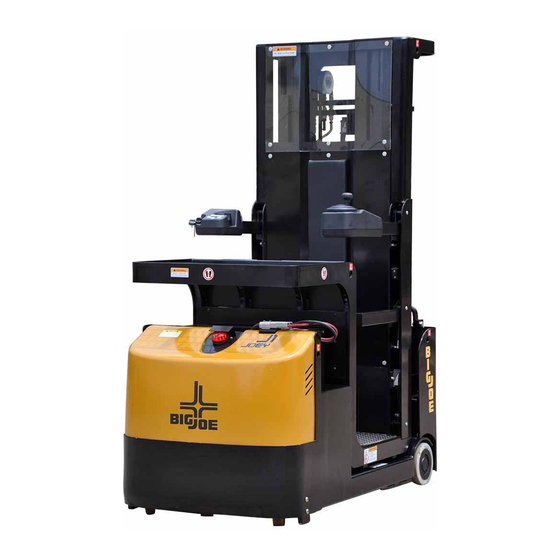
VEHICLE
Repair Parts Manual
www.bigjoesupport.com
MANUAL NO. BL-J1-192-0315 - 11-19-2019
PART NO. 901632
Advertisement
Table of Contents
Troubleshooting

Summary of Contents for Big Joe J1-192
- Page 1 Repair Parts Manual NOTE:This vehicle is for indoor and level surface use only. NOTE:For the most current parts information and service updates, please refer to the Big Joe Support site at www.bigjoesupport.com Big Lift LLC MANUAL NO. BL-J1-192-0315 - 11-19-2019 www.bigjoeforklifts.com...
- Page 2 WARNING Do not operate this vehicle unless you have been Before elevating platform be sure guardrail access authorized and trained to do so, and have read all gates are in place and lowered. Keep feet on platform warnings and instructions in Operator’s Manual and on floor at all times while using vehicle, never climb onto this vehicle.
- Page 3 BRAKE ASSY. REPLACEMENT ..5-1 THREE STAGE MAST 4 OPTIONAL EQUIPMENT 1 6 TRANSMISSION, DRIVE WHEEL, LOAD WHEEL AND CASTERS......6-1 INDUS TRIAL BATTERY 1 6-1 TRANSMISSION AND DRIVE MOTOR..6-1 6-2 LOAD WHEEL..........6-2 ILLUSTRATED PARTS BREAKDOWN 1 BL-J1-192-0315 - 11-19-2019...
- Page 4 BL-J1-192-0315 - 11-19-2019...
- Page 5 COMPONENT Battery retainer Control arms Battery Pick tray “Deadman” footswitch Warning light Operator platform Cover Load wheels Control panel Side gates Casters Rear tray for additional capacity and Frame storage Drive wheel Mast Hydraulic pump and reservoir BL-J1-192-0315 - 11-19-2019...
- Page 6 Warning decals are located to the left of the Instrument (See “page 1-3” for a copy of the form, also available panel. The data plate is mounted on the right side of at www.bigjoesupport.com) the Instrument panel. R6978 Figure 1-2 J1 Data Plate BL-J1-192-0315 - 11-19-2019...
- Page 7 1-3 BL-J1-192-0315 - 11-19-2019...
- Page 8 NOTES BL-J1-192-0315 - 11-19-2019...
- Page 9 Check "deadman” footswitch for proper operation. Monthly Check lift chain tension, lubrication & operation (see paragraph 2-9.) Quarterly Check lift cylinder for leakage. Quarterly Test electric steering. Quarterly Check steering gear for wear and lubricate. Semi-annually Inspect for chain wear (See SECTION BL-J1-192-0315 - 11-19-2019...
- Page 10 Gas formed during charging amount of gases be released from the battery. Also, is highly explosive and can cause seri- being a valve regulated battery, it never requires ous injury. watering. BL-J1-192-0315 - 11-19-2019...
- Page 11 OFF. Dispose in accordance with national environmental protection regulations or disposal laws. The manufac- Apply the emergency parking brake. turer’s disposal instructions must be followed * Please refer to the Big Joe Support site at www.bigjoesupport.com BL-J1-192-0315 - 11-19-2019...
- Page 12 Ensure chain is aligned and tracking properly and all links are pivoting freely. With lift carriage fully lowered, spray on a film of Moly Chain Lube. For more information see SECTION 7 BL-J1-192-0315 - 11-19-2019...
- Page 13 TYPE APPLICATION INDEX APPLICATION (Table 2-3) LUBRICANT Mast Spray No. 1 Full length of channel where rollers operate. Hydraulic Reservoir No. 2 With platform fully lowered, fill res- ervoir with hydraulic oil to level on dip stick. BL-J1-192-0315 - 11-19-2019...
- Page 14 Platform guard rails are undamaged and gates open / close freely. All nuts, bolts, pins, shafts, covers, bearings and wear pads are checked for proper installation, and do not have excessive wear, cracks or distortion. Continued on page 2 VERSION G PAGE 1 OF 2 BL-J1-192-0315 - 11-19-2019...
- Page 15 Owner / User, and that all discrepancies have been corrected prior to any further use of this machine. OWNER / USER OWNER / USER SIGNATURE: PRINTED NAME: DATE: DEALER DEALER SIGNATURE: PRINTED NAME: DATE: VERSION G PAGE 2 OF 2 BL-J1-192-0315 - 11-19-2019...
- Page 16 NOTES BL-J1-192-0315 - 11-19-2019...
- Page 17 Defective travel switch in con- Check and replace switch if defec- reverse at lower speeds; will not trol head. tive. travel at high speed. b. Operator platform raised above Lower operator platform below 47 47 inches. inches. BL-J1-192-0315 - 11-19-2019...
- Page 18 Platform does not lift to top. Pump a. Oil level too low. Add oil to reservoir. motor runs. b. Load larger than capacity. Refer to nameplate on side of mast for maximum load capacity. c. Batteries need charging. Charge batteries. BL-J1-192-0315 - 11-19-2019...
- Page 19 Defective potentiometer. Check and replace potentiometer if defective. d. Defective controller. Check for proper operation and replace if necessary. e. Defective steer motor. Replace if necessary. BL-J1-192-0315 - 11-19-2019...
- Page 20 Press the OUT button (6) to exit the tests. The display will show TESTER. Press the OUT button (6) again to return to Open- ing Zapi Menu. BL-J1-192-0315 - 11-19-2019...
- Page 21 107 Hz CUTBACK SPEED CUTBACK SPEED 2 CUTBACK SPEED 3 CURVE CUTBACK DEADMAN BRAKING HS (hard-soft) CUTBACK 100% FREQUENCY CREEP 1.20 Hz MAXIMUM CURRENT R6624 INCHING SPEED 0 Hz Figure 3-2 Zapi Handset INCHING TIME AUXILIARY TIME BL-J1-192-0315 - 11-19-2019...
- Page 22 If the alarm occurs perma- controller is active. nently, replace the controller. LOGIC FAILURE #2 This alarm occurs when the circuit, to Replace the Controller. compensate for the dead times of the sine waves, is failed. BL-J1-192-0315 - 11-19-2019...
- Page 23 The main contactor coil has been driven There are two possibilities: by the logic board, but the contactor The wires to the coil are interrupted does not close. or not well connected. The contact of the contactor is defective. BL-J1-192-0315 - 11-19-2019...
- Page 24 Then the outputs of the Current amplifi- ers must be in a narrow window close to 2.5 Vdc (from 2.26 V to 2.74 V). Otherwise this STBY I HIGH alarm occurs. BL-J1-192-0315 - 11-19-2019...
- Page 25 THERMIC SENS KO When the output of the thermal sensor It is necessary to replace the controller. on the base plate is higher than 4.95V or lower than 0.1V, the sensor is assumed defective and this alarm occurs. BL-J1-192-0315 - 11-19-2019...
- Page 26 The tiller switch active at key on The H&S input active at key on The Quick inversion active at key A failure in the logic is possible too. When all of the above conditions checked OK, replace the controller. 3-10 BL-J1-192-0315 - 11-19-2019...
- Page 27 This Multiplexer exists the lifting and the not lifting level on two distinct addresses. When the lifting and the not lifting outputs have the same logic level, the PLD device has failed and this alarm occurs. BL-J1-192-0315 - 11-19-2019 3-11...
- Page 28 CHECK UP NEEDED This is just a warning to perform pro- It is just enough to turn the CHECK UP grammed maintenance. DONE option to level ON after the maintenance is executed. 3-12 BL-J1-192-0315 - 11-19-2019...
- Page 29 2.2 to 2.8 Vdc. After the initial diagnosis this alarm occurs when the output of the cur- rent amplifiers at rest have a drift larger than ±0.15 V. BL-J1-192-0315 - 11-19-2019 3-13...
- Page 30 STEER HAZARD This is just a warning to inform that the steering controller is limiting the angle in the steering direction. No speed reduction occurs on the traction 3-14 BL-J1-192-0315 - 11-19-2019...
- Page 31 (Closed loop application only) if the slave uC detects the stator voltage phasor rotates in the opposite direction respect to the commanded position. BL-J1-192-0315 - 11-19-2019 3-15...
- Page 32 CAN Bus. From the request until the parameters are cor- rectly relieved, this warning occurs. The steer is not activated yet, and the safety relays remain open when this warning is present. 3-16 BL-J1-192-0315 - 11-19-2019...
- Page 33 CNA#9 and the minus the voltage on every stepper motor line battery (with the stepper motor at rest) is a sine wave with null mean voltage. is expected to be very low (close to 30 ohms) BL-J1-192-0315 - 11-19-2019 3-17...
- Page 34 Check the connections of the feedback back potentiometer (CPOT on potentiometer. This alarm occurs when CNB#6). It occurs if CPOT exits the one connection of the feedback poten- range of 0.3 Vdc to 4.7 Vdc. tiometer is broken. 3-18 BL-J1-192-0315 - 11-19-2019...
- Page 35 Vdc when switching on the key. In fact, when the safety contacts are open to a minus battery voltage (not 12 V). Search for a harness problem or replace the controller. BL-J1-192-0315 - 11-19-2019 3-19...
- Page 36 NOTES 3-20 BL-J1-192-0315 - 11-19-2019...
- Page 37 4-1. CONTROL ARM Remove the six screws from the lower cover. Sep- arate lower cover and upper cover. 4-1.1. Steering Control Removal. Engage the emergency power disconnect switch and turn off key switch. R8163 Figure 4-1 Control Arm (Left) BL-J1-192-0315 - 11-19-2019...
- Page 38 Engage the emergency power disconnect switch 12. Disengage the emergency power disconnect and turn off key switch. switch and turn on key switch. Remove the compartment cover as described in 4-2. COMPARTMENT COVER paragraph 4-2.1. 4-2.1. Cover Removal. BL-J1-192-0315 - 11-19-2019...
- Page 39 Remove the steering motor from the top of the Install the compartment cover as described in vehicle. paragraph 4-2.2. Disengage the emergency power disconnect 4-3.2. Motor Installation. switch and turn on key switch. Position the steering motor in the top of the motor compartment. BL-J1-192-0315 - 11-19-2019...
- Page 40 NOTES BL-J1-192-0315 - 11-19-2019...
- Page 41 Remove load wheel blocks and check operation. Engage the emergency power disconnect switch and turn off key switch. Disengage the emergency power disconnect switch and turn on key switch. Block load wheels. Remove the compartment cover as described in paragraph 4-2.1. BL-J1-192-0315 - 11-19-2019...
- Page 42 R8161 Figure 5-1 Transmission, Motor & Brake Assembly BL-J1-192-0315 - 11-19-2019...
- Page 43 Raise the vehicle off the ground to provide clear- 10. Install new drive assembly by reversing the steps ance for drive assembly (1, Figure 6-1) out the above. bottom. Securely block the vehicle to prevent movement. R8161 Figure 6-1 Drive System BL-J1-192-0315 - 11-19-2019...
- Page 44 Fig- Install seal from load wheel. 11-4. Position load wheel in the axle and install washer and nut. Tighten nut until there is a slight drag on load wheel. Secure nut with tab on washer. BL-J1-192-0315 - 11-19-2019...
- Page 45 DT_0001 Figure 6-2 Frame BL-J1-192-0315 - 11-19-2019...
- Page 46 R8161 Figure 6-3 Transmission, Motor & Brake Assembly BL-J1-192-0315 - 11-19-2019...
- Page 47 Tighten jam nuts securely while maintaining align- ment of clevis pin. Disengage the emergency power disconnect switch and turn on key switch. Test chain by operating Platform. If slack is still apparent, repeat above procedure. R8171 Figure 7-1 Chain Assembly BL-J1-192-0315 - 11-19-2019...
- Page 48 Remove cotter pin, flat washer, clevis pin and anchor connecting chain to inner mast. 10. Adjust the chains according to paragraph 7-2. 11. Disengage the emergency power disconnect switch and turn on key switch. BL-J1-192-0315 - 11-19-2019...
- Page 49 R8172 Figure 7-2 Elevation System - Part 1 BL-J1-192-0315 - 11-19-2019...
- Page 50 R8173 Figure 7-3 Elevation System - Part 2 BL-J1-192-0315 - 11-19-2019...
- Page 51 R8174 Figure 7-4 Platform Installation BL-J1-192-0315 - 11-19-2019...
- Page 52 7-5. LIFT CYLINDERS. NOTE: Removal and repair of lift cylinders are cov- ered in SECTION BL-J1-192-0315 - 11-19-2019...
- Page 53 Remove the hydraulic pump/motor assembly as hydraulic oil to bring to proper level. Use hydraulic described in paragraph 8-2.1. oil listed in Table 2-2. Refer to Figure 11-8 for disassembly and reas- Install the compartment cover as described in sembly. paragraph 4-2. BL-J1-192-0315 - 11-19-2019...
- Page 54 R8165 Figure 8-1 Hydraulic System BL-J1-192-0315 - 11-19-2019...
- Page 55 (10). Remove screw (8), lock washer (9), flat washer (10), angle (11), bracket (34) and header (15) Install relief valve (6, Figure 8-3), two washers (5) from cylinder (18). and connector on cylinder (25). BL-J1-192-0315 - 11-19-2019...
- Page 56 (16), lock washer (17) and flat washer (18). Position header (15), bracket (34) and angle (11) on top of cylinder (18) and secure with screw (8), lock washer (9) and flat washer (10). BL-J1-192-0315 - 11-19-2019...
- Page 57 R8176 Figure 8-3 Hydraulic Lines BL-J1-192-0315 - 11-19-2019...
- Page 58 R8172 Figure 8-4 Elevation System - Part 1 BL-J1-192-0315 - 11-19-2019...
- Page 59 RR8173 Figure 8-5 Elevation System - Part 2 BL-J1-192-0315 - 11-19-2019...
- Page 60 To prevent damage, use proper pipe clamp vise. The cylinder will be distorted if the vise is tightened too much. R8179 Secure the lift cylinder in a vise, clamping lightly Figure 8-6 Lift Cylinder (Secondary) at the base of the cylinder. BL-J1-192-0315 - 11-19-2019...
- Page 61 11. Adjust the chains according to paragraph 7-2. cylinder (25). 12. Install the compartment cover as described in Reconnect tube (3 or 10). paragraph 4-2. Install lift chains as described in paragraph 7-4. Fill the hydraulic reservoir. Use hydraulic oil listed Table 2-2. BL-J1-192-0315 - 11-19-2019...
- Page 62 NOTES 8-10 BL-J1-192-0315 - 11-19-2019...
- Page 63 Reconnect harness (to horn. battery. Install compartment covers as described in para- graph 4-2. 9-1.3. Panel Removal. Disengage the emergency power disconnect Engage the emergency power disconnect switch switch and turn on key switch. and turn off key switch. BL-J1-192-0315 - 11-19-2019...
- Page 64 R8167 Figure 9-1 Electrical System BL-J1-192-0315 - 11-19-2019...
- Page 65 Install mounting plate with sensor and secure with lock washers, three screws and three lock wash- four screws, four lock washers and four flat wash- ers. ers. Install the battery as described in paragraph 2-7. Reconnect harness o sensor. BL-J1-192-0315 - 11-19-2019...
- Page 66 Remove two screws (18, Figure 11-2) and discon- 23. Remove harness from the protective chain. nect mount (19) from bracket (20). 24. Install new harness by reversing the steps above. 10. Disconnect protective chain (45) from mount (19). BL-J1-192-0315 - 11-19-2019...
- Page 67 R8172 Figure 9-2 Elevation System - Part 1 BL-J1-192-0315 - 11-19-2019...
- Page 68 R8173 Figure 9-3 Elevation System - Part 2 BL-J1-192-0315 - 11-19-2019...
- Page 69 R8174 Figure 9-4 Platform Installation BL-J1-192-0315 - 11-19-2019...
- Page 70 R8175 Figure 9-5 Platform Assembly BL-J1-192-0315 - 11-19-2019...
- Page 71 SECTION 10 OPTIONAL EQUIPMENT 10-1. INDUSTRIAL BATTERY Contact you authorized Big Joe dealer for information on optional batteries and battery chargers. BL-J1-192-0315 - 11-19-2019 10-1...
- Page 72 NOTES 10-2 BL-J1-192-0315 - 11-19-2019...
- Page 73 SECTION 11F ILLUSTRATED PARTS BREAKDOWN Following is an illustrated parts breakdown of assemblies and parts associated with the J1 task support vehicle. BL-J1-192-0315 - 11-19-2019 11-1...
- Page 74 DT_0001 Figure 11-1 Frame 11-2 BL-J1-192-0315 - 11-19-2019...
- Page 75 227160239 - Red Used from Serial Number CK10-100007-60-02 COVER 227160240 - Red Used up to Serial Number CK10-100005-60-03 COVER 227160239 - Yellow Used from Serial Number CK10-100007-60-03 COVER 227160240 - Yellow CK10-100009-00 BLOCK 0000-000194-00 FLAT WASHER Ø8 BL-J1-192-0315 - 11-19-2019 11-3...
- Page 76 DT_0001 Figure 11-1Frame - Continued 11-4 BL-J1-192-0315 - 11-19-2019...
- Page 77 PLATE A.R. As Required 0000-000996-00 BOLT M16×45 0000-000060-00 LOCK WASHER Ø12 0000-000373-00 FLAT WASHER Ø12 0000-000372-00 SCREW M8×40 Used up to Serial Number 0000-000285-00 BOLT M12×35 226120059 Used up to Serial Number 0000-000630-00 NUT M12 226120059 BL-J1-192-0315 - 11-19-2019 11-5...
- Page 78 DT_0016 Figure 11-2 Platform Installation 11-6 BL-J1-192-0315 - 11-19-2019...
- Page 79 SCREW M10×25 0000-000322-00 SCREW M8×25 CK10-740000-10 RIGHT ARMREST CK10-760000-10 SQUARE TUBE RIGHT CK10-700002-60 SIDE ROLLER Used from serial number 225100041 0000-000071-00 FLATWASHER Ø10 A.R. Used from serial number 225100041 3010-020000-31 BOLT M10×45 Used from serial number 225100041 BL-J1-192-0315 - 11-19-2019 11-7...
- Page 80 R8175 Figure 11-3 Platform Assembly 11-8 BL-J1-192-0315 - 11-19-2019...
- Page 81 SCREW M4×12 0000-000122-00 LOCK WASHER Ø4 0000-000702-00 FLAT WASHER Ø4 CK10-560011-00 BRAKE SWITCH CK10-700001-60 WINDSHIELD This is an option that will derate the truck. Please TRAY ASSEMBLY contact the factory for infor- mation. 0000-000090-00 SCREW M6X12 BL-J1-192-0315 - 11-19-2019 11-9...
- Page 82 R8160 Figure 11-4 Caster Assembly - Used up to Serial Number 225170105 11-10 BL-J1-192-0315 - 11-19-2019...
- Page 83 CASTER WHEEL 0000-000426-00 NUT M10 1120-140004-00 SPRING 0000-000987-00 SNAP RING Φ80 0000-000057-00 NUT M12 0000-000063-00 LOCK WASHER Ø10 0000-000007-00 FLAT WASHER Ø10 0000-000435-00 FLAT WASHER Ø20 0000-000060-00 LOCK WASHER Ø12 0000-000373-00 FLAT WASHER Ø12 0000-000004-00 SCREW M5×12 BL-J1-192-0315 - 11-19-2019 11-11...
- Page 84 R8263 Figure 11-5 Caster Assembly - Used from Serial Number 225170106 11-12 BL-J1-192-0315 - 11-19-2019...
- Page 85 225170106 - 226180177 Used from Serial Number CK10-171004-00 BUFFER BLOCK 226180178 1115-032001-A0 0000-000740-00 NUT M8 0000-001413-00 BOLT M12×100 1115-032200-A0 WHEEL BRACKET 0000-001334-00 NUT M12 0000-000495-00 BOLT M12×85 0000-000435-00 FLATWASHER Ø20 1120-143001-00 SHAFT 0000-000020-00 BEARING 1115-172101-H0 PU WHEEL BL-J1-192-0315 - 11-19-2019 11-13...
- Page 86 R8162 Figure 11-6 Drive System 11-14 BL-J1-192-0315 - 11-19-2019...
- Page 87 Used from Serial Number CK10-200000-1B DRIVE ASSEMBLY 224190037 - See Trans- mission and Motor section Used up to Serial Number 1280-520009-10-01 SWITCH WIRE HARNESS II 226170005 Used from Serial Number 1280-520009-1A-01 SWITCH WIRE HARNESS II 226170006 BL-J1-192-0315 - 11-19-2019 11-15...
- Page 88 R8161 Figure 11-7 Transmission, Motor & Brake Assembly 11-16 BL-J1-192-0315 - 11-19-2019...
- Page 89 CK10-200001-10 GEAR 0000-000321-00 SCREW M8×20 0000-000386-00 SCREW M6×20 0000-000056-00 LOCK WASHER Ø6 CK10-200002-10 WASHER CK10-220005-10 KB-SENSOR 0000-000013-00 GREASE FITTING M8 0000-000226-00 KEY 6×6×16 0000-000204-00 KEY 3×5×13 0000-000436-00 NUT M12×1.5 CK10-220001-10 SHAFT SEAL Ø25×40×7 CK10-240001-20 KB-SENSOR,STEERING MOTOR BL-J1-192-0315 - 11-19-2019 11-17...
- Page 90 DT_0007 Figure 11-8 Hydraulic System 11-18 BL-J1-192-0315 - 11-19-2019...
- Page 91 2112-440000-10 BLOCK CROSS 225180128 Used from Serial Number CK10-404000-30 BLOCK CROSS 225180129 CK11-450000-00 ACCUMULATOR 2701-141400-00 CONNECTOR M14×1.5-M14×1.5 0000-000176-00 FLAT WASHER Ø8 CK10-403000-30 PRESSURE SWITCH Used from Serial Number CK10-520021-00 PRESSURE SWITCH WIRING 225180129 0000-001674-00 WASHER Ø12 BL-J1-192-0315 - 11-19-2019 11-19...
- Page 92 R8166 Figure 11-9 Hydraulic Pump and Motor Assembly 11-20 BL-J1-192-0315 - 11-19-2019...
- Page 93 RELEASE VALVE 2125-430010-00 SOLENOID VALVE 2125-430022-00 STEEL CLAMP CK10-490003-30 VALVE 2125-430013-00 VALVE CAVITY PLUG 2130-430008-0A PLASTIC TUBE 2130-430009-0A FILTER 0000-000620-00 BOLT M6X16 0000-000056-00 LOCK WASHER Ø6 1120-420017-00 CONTACTOR 2130-430007-0A CABLE INSULATED CK10-490004-30 RELIEF VALVE 2125-430023-00 BRUSH BL-J1-192-0315 - 11-19-2019 11-21...
- Page 94 R8176 Figure 11-10 Hydraulic Lines 11-22 BL-J1-192-0315 - 11-19-2019...
- Page 95 CONNECTOR M16×1.5-M16×1.5 CK10-435000-60 HOSE Used up to Serial number CK10-432000-60 METALLIC OIL PIPE I 2281200213 Used from Serial number CK10-432000-6A METALLIC OIL PIPE I 2281200214 0000-000321-00 SCREW M8×20 0000-000159-00 LOCK WASHERLOCK WASHER Ø8 0000-000176-00 FLAT WASHER Ø8 BL-J1-192-0315 - 11-19-2019 11-23...
- Page 96 DT_0014 Figure 11-11 Elevation System - Part 1 11-24 BL-J1-192-0315 - 11-19-2019...
- Page 97 Used up to Serial Number 225170105 CK10-520015-10 WARNING LAMP Used from Serial Number 225170106 CK10-600002-60 BOARD CK10-520016-60 SWITCH WIRING OF TRIPLEX MAST 0000-000998-00 SCREW M3×8 Used up to Serial Number 225170105 0000-000139-00 NUT M4 Used from Serial Number 225170106 BL-J1-192-0315 - 11-19-2019 11-25...
- Page 98 DT_0014 Figure 11-11Elevation System - Part 1 - Continued 11-26 BL-J1-192-0315 - 11-19-2019...
- Page 99 0000-000593-00 BOLT M12×40 Used from serial number 0000-000122-00 LOCKWASHER Ø4 225170106 Used from serial number 0000-000702-00 FLATWASHER Ø4 225170106 CK10-510034-60 WIRE GROOVE Used from serial number 226210150 CK10-510035-60 PLATE Used from serial number CK10-600008-60 COVER 226210148 BL-J1-192-0315 - 11-19-2019 11-27...
- Page 100 DT_0015 Figure 11-12 Elevation System - Part 2 11-28 BL-J1-192-0315 - 11-19-2019...
- Page 101 CK10-660000-30-04 CHAIN ASSEMBLY II Used up to Serial number CK10-500001-60 DRAG CHAIN MOUNTING PLATE 226200269 Used from Serial number CK10-500001-6A DRAG CHAIN MOUNTING PLATE 226200270 0000-000618-00 SCREW M6×12 CK10-510005-00 DRAG HEAD II CK10-510003-00-12 DRAG CHAIN II BL-J1-192-0315 - 11-19-2019 11-29...
- Page 102 R8177 Figure 11-13 Full Free Lift Cylinder - Used up to Serial number 2281200213 11-30 BL-J1-192-0315 - 11-19-2019...
- Page 103 RING BACK UP 55×20×2.5 0000-001091-00 ROD PACKING 45×55×6 0000-001090-00 COLLAR 45×55×2 3218-420005-30 RELEASE VALVE 3218-420004-30 SOLENOID VALVE 0000-000344-00 O-RING 20×2.4 CK10-420005-3A SPRING 3218-420006-30 COLLAR 0000-000607-00 COLLAR Ø22 0000-000133-00 WASHER Ø6 0000-001137-00 SCREW M6×5 0000-000685-00 O-RING 65×3.1 BL-J1-192-0315 - 11-19-2019 11-31...
- Page 104 DT_0025 Figure 11-14 Full Free Lift Cylinder - Used from Serial number 2281200214 11-32 BL-J1-192-0315 - 11-19-2019...
- Page 105 RING BACK UP 55×20×2.5 0000-001091-00 ROD PACKING 45×55×6 0000-001090-00 COLLAR 45×55×2 3218-420005-30 RELEASE VALVE 3218-420004-30 SOLENOID VALVE 0000-000344-00 O-RING 20×2.4 CK10-420005-3A SPRING 3218-420006-30 COLLAR 0000-000607-00 COLLAR Ø22 0000-000133-00 WASHER Ø6 0000-001137-00 SCREW M6×5 0000-000685-00 O-RING 65×3.1 BL-J1-192-0315 - 11-19-2019 11-33...
- Page 106 R8179 Figure 11-15 Lift Cylinder (Secondary) - Used up to Serial Number 2281500212 11-34 BL-J1-192-0315 - 11-19-2019...
- Page 107 PISTON ROD 2125-410005-3A BUSHING 0000-000520-00 COLLAR Ø24 2125-410002-30 RING BACK UP CK10-411000-30-04 CYLINDER Used up to Serial number 2125-410006-30 S2314158 Used from Serial number 3010-020000-16 BOLT M8×30 S2314159 0000-001092-00 SCREW M6×6 0000-000133-00 WASHER Ø6 0000-000609-00 O-RING 52.5×3.1 BL-J1-192-0315 - 11-19-2019 11-35...
- Page 108 DT_0024 Figure 11-16 Lift Cylinder (Secondary) - Used from Serial Number 2281500213 11-36 BL-J1-192-0315 - 11-19-2019...
- Page 109 LIFT CYLINDER ASSEMBLY Used on Lift Height 162” RING WIPER 35×43×5-6.5 ROD PACKING 35×45×6 O-RING 52.5×3.1 O-RING 48×3.1 WASHER Ø6 RING BACK UP CK10-ZBG-3B SEAL KIT FOR LIFTING CYLINDER Includes Item 1, 2, 3,4,5 & 6 BL-J1-192-0315 - 11-19-2019 11-37...
- Page 110 R8171 Chain Assembly Figure 11-17 Chain Assembly 11-38 BL-J1-192-0315 - 11-19-2019...
- Page 111 CHAIN ANCHOR 227160164 - For Lifting Mast Used from Serial Number 2125-640004-00 CHAIN ANCHOR 227160165 - For Lifting Mast 2125-640003-00 CHAIN ANCHOR For platform 3070-010000-03 COTTER PIN Ø3.2×40 0000-000176-00 FLAT WASHER Ø8 CK10-600007-00 WASHER A.R. As Required BL-J1-192-0315 - 11-19-2019 11-39...
- Page 112 R8163 Figure 11-18 Control Arm (Left) 11-40 BL-J1-192-0315 - 11-19-2019...
- Page 113 3020-050000-17 SCREW M5×8 0000-000941-00 SNAP RING Φ26 CK11-560002-00 STEPPING MOTOR 0000-000004-00 SCREW M5×12 CK11-520007-00 STEPPING MOTOR WIRE HARNESS CK11-310004-00 LOWER COVER OF LEFT ARMREST 0000-000661-00 SCREW M5×20 CK11-520002-00 WIRE HARNESS OF OPERATION PANEL(L) 0000-000001-00 SCREW M6×20 BL-J1-192-0315 - 11-19-2019 11-41...
- Page 114 R8164 Figure 11-19 Control Arm (Right) 11-42 BL-J1-192-0315 - 11-19-2019...
- Page 115 Used between CK11-520008-0A FWD. / REV. SWITCH WIRE HARNESS 05-09-2013 and Serial # 227210207 0000-000001-00 SCREW M6×20 CK10-520003-00 WIRE HARNESS OF OPERATION PANEL(R) CK11-320002-00 LOWER COVER OF RIGHT ARMREST 0000-000661-00 SCREW M5×20 0000-000490-00 HARNESS CLAMP 1280-560004-00 BUTTON BL-J1-192-0315 - 11-19-2019 11-43...
- Page 116 R8167 Figure 11-20 Electrical System 11-44 BL-J1-192-0315 - 11-19-2019...
- Page 117 FLAT WASHER Ø6 0000-000550-00 NUT M8 CK10-510030-40 BUZZER PLATE 3712-405000-00 ALARM BUZZER Option CK10-520020-00 ALARM BUZZER WIRING Option Used from Serial Number 0000-000122-00 LOCK WASHER Ø4 225170106 Used from Serial Number 0000-000702-00 FLAT WASHER Ø4 225170106 BL-J1-192-0315 - 11-19-2019 11-45...
- Page 118 R8168 Figure 11-21 Control Panel 11-46 BL-J1-192-0315 - 11-19-2019...
- Page 119 0000-000074-00 SCREW M6×20 0000-000210-00 FLAT WASHER Ø8 0000-000196-00 NUT M8 2322-510003-00 COPPER CONDUCTOR 1220-500005-00 TERMINAL 0000-000088-00 SCREW M4×8 CK10-510002-00 COPPER CONDUCTOR Used from Serial # CK10-560002-00 CONTACTOR BRACKET 2281000299 Used from Serial # 3020-270000-01 SCREW 2281000299 BL-J1-192-0315 - 11-19-2019 11-47...
- Page 120 R8169 Figure 11-22 Wiring Harness 11-48 BL-J1-192-0315 - 11-19-2019...
- Page 121 Wiring Harness QTY. POS. PART NUMBER DESCRIPTION NOTES REQD. CK10-520001-0A MASTER WIRING HARNESS 1120-500010-00 FUSE 10A CK10-520010-00-05 MULTI-CORE CABLE HARNESS CK10-520017-00 COMMUNICATION WIRING BL-J1-192-0315 - 11-19-2019 11-49...
- Page 122 R8170 Figure 11-23 Wiring Cables 11-50 BL-J1-192-0315 - 11-19-2019...
- Page 123 DRIVE MOTOR CABLE U CK10-531002-00 DRIVE MOTOR CABLE V CK10-531003-00 DRIVE MOTOR CABLE W CK10-531006-10 STEERING MOTOR CABLE W CK10-531005-10 STEERING MOTOR CABLE V CK10-531004-10 STEERING MOTOR CABLE U CK10-531013-00 (D-AC0) CABLE CK10-531007-00 (D-EPS-AC0) CABLE CK10-531008-00 (EPS-AC0) CABLE BL-J1-192-0315 - 11-19-2019 11-51...
- Page 124 Big Lift LLC PART NO. 901632...
Need help?
Do you have a question about the J1-192 and is the answer not in the manual?
Questions and answers