FAAC S418 Manual
Electromechanical swing gate operator
Hide thumbs
Also See for S418:
- Manual (31 pages) ,
- User manual (30 pages) ,
- Instruction manual (16 pages)
Table of Contents
Advertisement
Advertisement
Table of Contents

Related Manuals for FAAC S418


Summary of Contents for FAAC S418
- Page 1 S418 S418 Electromechanical Swing Gate Operator FAAC International Inc. FAAC International Inc. Headquarter & East Coast Operations West Coast Operations 3160 Murrell Rd 357 South Acacia Avenue Rockledge, FL 32955 Fullerton, CA 92831 Tel. 800 221 8278 www.faacusa.com...
-
Page 2: Table Of Contents
2. Inputs / Outputs Description UL325 Gate Operator Classifications 3. Safety Devices Connections Installing the Warning Signs 4. Programming 5. Led Diagnostics S418 OPERATOR 6. Time Learning (Set-Up) DESCRIPTION AND SPECIFICATIONS 7. Obstacle Detection 8. Enclosure Dimensions 9. Power Connection Technical Specifications 10. -
Page 3: Important Safety Information
Guarding is supplied for exposed rollers. IMPORTANT SAFETY INFORMATION The operator instructions shall list the maximum number of open and close entrapment protection devices capable of being connected to the operator. WARNING - to reduce the risk of severe injury or death: b) The operator is intended for installation only on gates used READ AND FOLLOW ALL INSTRUCTIONS. -
Page 4: General Safety Precautions
GENERAL SAFETY PRECAUTIONS For gate operators that utilize a contact sensor (edge sensor or similar): One or more contact sensors shall be located where Gate Construction the risk of entrapment or obstruction exists, such as at Vehicular gates should be constructed and installed in the leading edge, trailing edge, and postmounted both accordance with ASTM F2200: Standard Specification for inside and outside of a vehicular horizontal slide gate. -
Page 5: Ul325 Gate Operator Classifications
Installing the Warning Signs This FAAC swing gate operator is supplied with two warning signs to alert people that a possible hazard exists and that appropriate actions should be taken to avoid the hazard or to reduce exposure to it. -
Page 6: S418 Operator
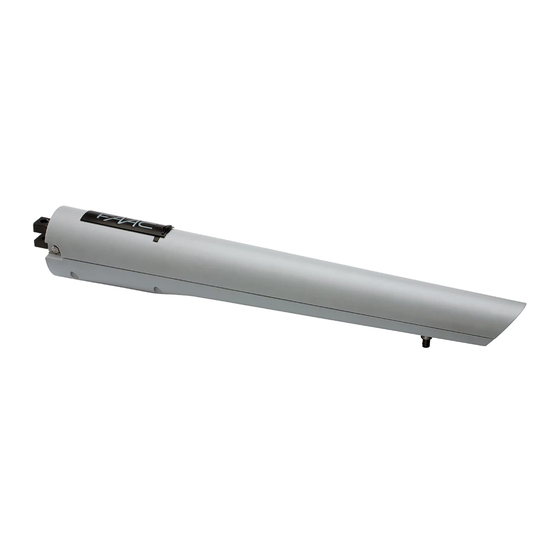
1. DESCRIPTION AND SPECIFICATION The FAAC 418 is an automatic gate operator for swinging gate leafs. It is designed for residential applications and its versatility can accommodate different combinations of gate weights and lengths. The self-contained S418 operator consists of an electric motor that drives a worm screw housed in an aluminum casing, with built in positive stops. -
Page 7: Technical Specifications
1.2 Technical Specifications 2. INSTALLATION Power Supply 24 Vdc 2.1 Preliminary Checks Nominal Power 35 W The structure of the gate directly influences the reliability Absorbed Current 1.5 A and safety of the automated system. To ensure correct Maximum Thrust Force 404 lbf (180 daN) operation, the structure of the gate must have the following 13.8 in (350 mm) *... -
Page 8: Installing The Operator
2.2.1 General Rules for Determining Installation Values • To obtain opening of the leaf to 90°: A+B=C. If pillar dimensions or hinge position do not allow the installa- tion of the operator, cut a niche into the pillar (as shown in Fig. •... - Page 9 Install the rear bracket as shown in Figure 10, so as to follow the A and B values determined previously. 2⅛ Fig. 12 Dimensions in Inches 1⅜ Fig. 13 Dimensions in Inches Fig. 10 Secure the rear fork of the operator as indicated in Fig. 11. Secure the front bracket to the operator as indicated in Fig.
-
Page 10: Wiring The Operator
If the cable has to be replaced, use a UL rated cable for outdoor use. 2.5 Mechanical Stops The S418 operator is supplied with mechanical stops on opening and closing as standard. These may be used in place Fig. 16 of mechanical stop-points for the leaf. -
Page 11: Manual Operation
Move the mechanical stop until it is close to the front side of the bracket, as indicated in Fig. 22. Tighten the bolt. The mechanical stop is coupled to a toothed section on the operator's body, Fig. 21 Ref. 2. In case of difficulties moving the stop check that the coupling is free. -
Page 12: Restoring Normal Operation
For repairs, refer to FAAC authorized service centers. NOTE: During the first cycle, the operator might not slow down correctly. Wait for the end of the cycle and then give the... -
Page 13: E024U Control Board
E024U CONTROL BOARD 1. DESCRIPTION & CHARACTERISTICS SETTING DL14 DL15 DL16 DL17 DL18 DL19 DL20 DL21 DL22 Fig. A1 TECHNICAL SPECIFICATIONS LAYOUT AND COMPONENTS RADIO Main power supply Connector for the radio receiver 115 V~ 50/60 Hz BATTERY Secondary power Connector for the backup battery 24 Vdc - 16 A max. -
Page 14: Inputs / Outputs Description
2. INPUTS / OUTPUTS DESCRIPTION Encoder 24 VDC Maglock B STP CL OP OPEN Fig. A2 LABEL FUNCTION 2 EASY 2 EASY 2easy BUS input for encoders (S800H and S450H only), XIB and loop detector boards OPEN A N.O. Contact for total opening command OPEN B: N.O. -
Page 15: Safety Devices Connections
3. SAFETY DEVICES CONNECTIONS Entrapment protection To comply with the UL325 standard for gate operators every Connection of One Pair of Monitored Closing Photocells entrapment zone, as defined in ASTMF2200, must be pro- tected by two independent entrapment protection devices. One of the devices is inherent in the E024U control boards design, the other can be external, like a photocell or an edge sensor. - Page 16 Only one monitored photocell can be connected to the Closing or Opening safety inputs. More than one photocell Connection of One Pair of Closing Photocells or other device can be connected to the safety inputs, but (monitored), One Pair of Opening Photocells they will not be monitored.
-
Page 17: Programming
4. PROGRAMMING DIP SWITCH DS1 SETTINGS FOR OPERATING LOGIC OPERATING LOGIC DS 1: SW 1 - SW 2 - SW 3 PAUSE LOGIC SW 1 SW 2 SW 3 DESCRIPTION TIME E (default) One command opens, the next one closes. A command during opening stops the gate Semiautomatic 0 - 4... - Page 18 ADJUSTING TRIMMERS – FORCE ADJUSTMENT MOTOR 1 Turn clockwise to increase the opening and closing force TR 2 – FORCE ADJUSTEMENT MOTOR 2 Turn clockwise to increase the opening and closing force TR 3 – SPEED ADJUSTMENT FOR MOTOR1 AND MOTOR 2 Turn clockwise to increase the opening and closing speed TR 4 –...
- Page 19 DIP SWITCH DS1 SETTINGS FOR BOARD SETUP BOARD SETUP DS 1: SW 4 to SW 12 The opening of leaf 2 is delayed after the opening of leaf 1. This is to avoid SW 4 OPENING DELAY the gate leafs interfering with each other during the initial part of the move- 0 sec (default) ment.
-
Page 20: Led Diagnostics
S450H, S800H Active if the gate is Open or in Pause. DS1-10 Not active in all other states S418 Warning light output with no pre-flashing. War- 415, 390, 770 ning lamp will be flashing while gate is moving 5. LED DIAGNOSTICS... - Page 21 LED STATUS In BOLD the normal state with gate closed and working DESCRIPTION ON STEADY BLINKING Board working on AC Board working on LED BATTERY Battery charging power battery power or ext supply LED +24 Main power present Main power OFF SLOW BLINK (1 sec.
-
Page 22: Time Learning (Set-Up)
The diagnostic LED shows only one error condition at a time, with the priority of the below table. In case there is more than one error once one is eliminated the LED will show the next LED ERROR DISPLAY NUMBER OF ERROR CONDITION SOLUTION FLASHES... -
Page 23: Obstacle Detection
At the point where you want the slowdown to start give an This is a more detailed description of what happens after an OPEN A command with the push button or the remote that obstacle detection: is already stored in memory. Leaf 2 starts to slow down and Gate opening, obstacle detected: stops when it reaches the mechanical stop or FCA2. -
Page 24: Power Connection
On the back panel there are: the control board, the power supply AC POWER CONNECTION and additional accessories. To connect AC power to the controller: 1. Turn the circuit breaker for the AC gate operator power OFF before connecting the AC input wires. Power outlet AC connection and switch... -
Page 25: Backup Battery
For the upgrade you need a USB Flash Drive, where you have BLACK 12VDC, 8 amp Battery to copy the file supplied by FAAC. Then follow these steps: JUMPER Disconnect the batteries if they are present. 12VDC, 8 amp Turn the AC power off and insert the Flash Drive into the... -
Page 26: Function Logics
12. FUNCTION LOGICS LOGIC “E” PULSES SYSTEM STATUS OPEN A OPEN B STOP FSW OP FSW CL FSW CL/OP no effect no effect no effect CLOSED opens the leaves opens leaf 1 no effect (OPEN disabled) (OPEN disabled) (OPEN disabled) stops and opens at release immediately stops operation... - Page 27 (1) if the cycle began with OPEN-B (leaf 1), both leaves are activated at opening LOGIC “EP” PULSES SYSTEM STATUS OPEN A OPEN B STOP FSW OP FSW CL FSW CL/OP no effect no effect no effect CLOSED opens the leaves opens leaf 1 no effect (OPEN disabled)
- Page 28 LOGIC “B” PULSES SYSTEM STATUS OPEN A OPEN B STOP FSW OP FSW CL FSW CL/OP no effect no effect no effect CLOSED opens the leaves no effect no effect (OPEN disabled) (OPEN disabled) (OPEN disabled) stops and, at release, closes OPENING no effect closes leaves...
-
Page 29: Accessories
13. ACCESSORIES SHADOW LOOP INTERFACE (p/n 790062) XIB board connections with no opening safety Through the use of the XIB interface board you can connect an additional loop detector (center or shadow) to the E024U Interface board to keep the gate open if vehicles are obstructing the N.C. - Page 30 XIB board connections and second opening safety XIB board connections and only one opening safety Interface Interface N.C. N.C. Encoder N.O. Encoder N.O. Detector Detector OPEN SAFETY 1 MONITORED OPEN SAFETY MONITORED OPEN SAFETY 2 MONITORED RX= Receiver Photocell RX= Receiver Photocell Fig.
- Page 31 The face board will blink briefly and then will stay ON solid if the board is designed to fit in the FAAC standard 16” x 14” enclo- BUS connection is working correctly. sure on the existing DIN rail. To connect the interface board:...
-
Page 32: Spare Parts Diagram
Part Number Description 713002 Triangle Manual Release Key 63003356 S418 Complete Release Group 63000563 S418 Bodies Group 63002565 S418 Front and Rear Mounting Brackets 63003355 S418 Worm Screw Group 63001615 Motor S418 718366 Pin Long w/ C Clip 7228015 Rear Fork... - Page 33 LIMITED WARRANTY FAAC International, Inc. (“Seller”) warrants the first Purchaser All products sold by the Seller are subject to design and/or of the product to be free from defects in material and work- appearance modifications, which are production standards manship for a specific period as defined by the Warranty at the time of shipment.
- Page 34 NOTES: _________________________________________________________________________________________ _________________________________________________________________________________________ _________________________________________________________________________________________ _________________________________________________________________________________________ _________________________________________________________________________________________ _________________________________________________________________________________________ _________________________________________________________________________________________ _________________________________________________________________________________________ _________________________________________________________________________________________ _________________________________________________________________________________________ _________________________________________________________________________________________ _________________________________________________________________________________________ _________________________________________________________________________________________ _________________________________________________________________________________________ _________________________________________________________________________________________ _________________________________________________________________________________________ _________________________________________________________________________________________...
- Page 35 NOTES: _________________________________________________________________________________________ _________________________________________________________________________________________ _________________________________________________________________________________________ _________________________________________________________________________________________ _________________________________________________________________________________________ _________________________________________________________________________________________ _________________________________________________________________________________________ _________________________________________________________________________________________ _________________________________________________________________________________________ _________________________________________________________________________________________ _________________________________________________________________________________________ _________________________________________________________________________________________ _________________________________________________________________________________________ _________________________________________________________________________________________ _________________________________________________________________________________________ _________________________________________________________________________________________ _________________________________________________________________________________________...
- Page 36 S418 - I0806 - Rev.C - US © 2021, FAAC International, Inc. - All Rights Reserved Published in Jan. 2021...
Need help?
Do you have a question about the S418 and is the answer not in the manual?
Questions and answers