Advertisement
Quick Links
Advertisement

Related Manuals for Major tech MT876


Summary of Contents for Major tech MT876
- Page 1 INSTRUCTION MANUAL MT876 600V AC/DC TRMS MULTIMETER...
- Page 3 Contents Page no...
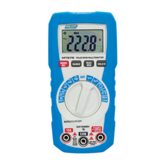
- Page 4 Introduction The meter measures AC/DC Voltage and Current, Resistance, • Diode Test, Continuity, Capacitance, Frequency, Duty Cycle and Temperature. • The meter also tests 1.5V and 9V batteries and offers a Non- Contact AC Voltage detector. • In addition, the meter detect Live/Neutral wire through a single test lead by contact.
- Page 5 2.1. Input Limits Function Maximum Input Voltage AC or DC 600V AC/DC Frequency, Resistance, Capacitance, 250V AC/DC Continuity, Diode Test, Temperature 10A Current AC or DC 10A/600V (6.3x32mm) fast acting Fuse uA/mA Current AC or DC 500mA/600V (6.3x32mm) fast acting Fuse Battery Test 20V AC/DC...
-
Page 6: Brief Description
2.4. Safety Category Ratings Category Rating Brief Description Typical Applications CAT II Single phase • Household appliances, power receptacles and tools connected loads • Outlets more than 30ft (10m) from a Cat III source • Outlets more than 60ft (20m) from a Cat IV source CAT III Three phase circuits... - Page 7 3. Description 3.1. Meter Description 1 - LCD Display 9 - COM Input Jack 2 - Non-Contact Voltage Indicator 10 - Positive Input Jack 3 - MODE/RELATIVE Button 11 - Non-Contact Voltage 4 - RANGE Button Detector 5 - MAX/MIN Button 12 - Lanyard Hole 6 - HOLD/Backlight Button 13 - Test Lead Holders...
- Page 8 3.2. Symbols Used on LCD Display 1 - Auto Power Off Auto Ranging Maximum Minimum Display Hold Diode Test Continuity Relative Mode Non-Contact AC Voltage Detection 10 - Live/Neutral Wire Measurement Function 11 - Degree Celsius/Degree Fahrenheit 12 - Units of Measure List 13 - Measurement Reading 14 - Low Battery 15 - Battery Test...
-
Page 9: Max/Min Button
4. Button Function 4.1. MODE and REL Button • Press the MODE Button to select AC/DC Voltage, AC/DC Current, Frequency, Duty Cycle, Ohms, Diode Test, Continuity or Capacitance, Temperature, NCV and Live. • Press the REL Button for >2 second to turn on or off the Relative function. •... - Page 10 HOLD/Backlight Button 4.4. Press the HOLD/Backlight Button to turn on or off the HOLD • function Press the HOLD/Backlight Button for >2 second to turn on or off • the Backlight function. Auto Power Off 4.5. The auto off feature will turn the meter off after 15 minutes. •...
- Page 11 5. Operating Instructions 5.1. AC/DC Voltage Measurement Observe all safety precautions when working on live WARNING: voltages. CAUTION: Do not measure voltages if a motor on the circuit is being switched ON or OFF. Large voltage surges may occur that can damage the meter.
- Page 12 Frequency/Duty Cycle Measurement (Electronic) 5.2. Observe all safety precautions when working on live WARNING: voltages. Set the rotatory function switch to the Hz/% Position. Insert the black test lead banana plug into the negative COM Input Jack; Insert the red test lead banana plug into the Positive Input Jack.
- Page 13 5.3. AC/DC Current Measurement WARNING: Observe all safety precautions when working on live circuits. Measurements in the 10A range should be limited to 30 seconds maximum every 15 minutes. 1. Insert the black test lead banana plug into the COM Input Jack. 2.
- Page 14 Resistance Measurement 5.4. Never test resistance on a live circuit. WARNING: Set the rotary function switch to the CAP Position. 2. Press the MODE Button until the “ ” symbol appears on the LCD display. 3. Insert the black test lead banana plug into the negative COM Input Jack;...
- Page 15 Diode Test 5.5. Never test diodes on a live circuit. WARNING: Set the rotary function switch to the CAP Position. 2. Press the MODE Button until the “ ” symbol appears on the LCD display. 3. Insert the black test lead banana plug into the negative COM Input Jack;...
- Page 16 Continuity Check 5.6. Never test continuity on a live circuit. WARNING: Set the rotary function switch to the CAP Position. 2. Press the MODE Button until the “ ” symbol appears on the LCD display. 3. Insert the black test lead banana plug into the negative COM Input Jack;...
- Page 17 Capacitance Measurement 5.7. To avoid electric shock, disconnect power to the unit WARNING: under test and discharge all capacitors before taking any capacitance measurements. Remove the batteries and unplug the line cords. Set the rotary function switch to the CAP Position. 2.
- Page 18 Temperature Measurement 5.8. Do not touch the temperature probe to live circuits. WARNING: 1. Set the function switch to the Temp Position. 2. Press the MODE Button to indicate °C or °F. 3. Connect the temperature probe to the banana plug adapter, note the - and + markings on the adapter.
- Page 19 Non-Contact AC Voltage Detection 5.9. Risk of Electrocution. Before use, always test the Voltage WARNING: Detector on a known live circuit to verify proper operation. 1. Set the rotary function switch to the NCV/Live Position. 2. Press the MODE Button to select readings in “NCV”. 3.
- Page 20 Contact Type Live/Neutral Wire Measurement 5.10. Risk of Electrocution. Before use, always test the Voltage WARNING: Detector on a known live circuit to verify proper operation. 1. Set the rotary function switch to the NCV/Live Position. 2. Press the MODE Button to select readings in “Live”. 3.
- Page 21 Battery Test 5.11. Do not connect to circuits that exceed 20V AC RMS or WARNING: 20V DC when the meter is set to 1.5V or 9V BATT Position. 1. Set the rotary function switch to the 1.5V or 9V BATT. Position. 2.
-
Page 22: Maintenance And Cleaning
6. Maintenance and Cleaning This Multimeter is designed to provide years of dependable service, if the following care instructions are performed: 1. Keep the meter dry, if it gets wet, wipe it off. 2. Use and store the meter in normal temperatures, temperature extremes can shorten the life of the electronic parts and distort or melt plastic parts. -
Page 23: Specifications
9. Specifications 9.1.Specifications Range Resolution Function Accuracy 4.000V 0.001V ±(1.2% + 3 digits) AC True RMS Voltage 0.01V 40.00V 0.1V 400.0V ±(1.2% + 5 digits) 600V All AC voltage ranges are specified from 5% of range to 100% of range. AC Voltage Bandwidth: 50Hz to 60Hz (All wave) 50Hz to 1kHz (Sine wave). - Page 24 Range Resolution Function Accuracy 400.0Ω 0.1Ω Resistance 0.001kΩ 4.000kΩ ±(1.2% + 5 digits) 0.01kΩ 40.00kΩ 0.1kΩ 400.0kΩ 4.000MΩ 0.001MΩ ±(2.5% + 8 digits) 40.00MΩ 0.01MΩ ±(3.0% + 8 digits) 99.99nF 0.01nF ±(3.5% + 40 digits) Capacitance 0.1nF 999.9nF ±(3.0% + 5 digits) 0.001μF 9.999μF 0.01μF...
- Page 25 9-2.General Specifications Insulation Class 2, Double Insulation Diode Test Test current approx.1mA , open circuit voltage of 3V typical Continuity Test Audible signal if the resistance is <50Ω Battery Test current 9V (approx.6mA); 1.5V (approx.30mA) Low Battery Indication “ ” is displayed Display 4000 count LCD Over Range Indication “OL”...
- Page 28 MAJOR TECH (PTY) LTD www.major-tech.com www.majortech.com.au sales@major-tech.com info@majortech.com.au...
Need help?
Do you have a question about the MT876 and is the answer not in the manual?
Questions and answers