
Summary of Contents for QSC Q-SYS NC Series
- Page 1 ™ Hardware User Manual Q-SYS NC Series Cameras ePTZ NC-110 NC-12x80 NC-20x60 TD-001654-01-A *TD-001654-01*...
-
Page 2: Important Safety Instructions
QSC authorized service station or an authorized QSC International Distributor. QSC is not responsible for any injury, harm, or related damages arising from any failure of the customer, owner, or user of the apparatus to facilitate those repairs. -
Page 3: Warranty
For a copy of the QSC Limited Warranty, visit the QSC, LLC., website at www.qsc.com. RoHS Statement The QSC Q-SYS NC Series: NC-1 10, NC-12x80, and NC-20x60 are in compliance with European Directive 2015/863/EU – Restriction of Hazardous Substances (RoHS2). -
Page 4: What's In The Box
Introduction The QSC Q-SYS™ NC Series comprises three camera models: NC-12x80, NC-20x60, and NC-1 10. These cameras send IP streams across a Q-LAN network to certain Q-SYS Core processors and peripherals, which bridge this IP signal to a USB signal for host computers to use in software applications. - Page 5 Connections and Controls (NC-12x80 and NC-20x60 PTZ) Front Panel Status LED (Green) • Off indicates the camera is in standby mode; network streams are off. • On indicates the camera is streaming video over the network. • Blinking indicates the ID mode is on. 2.
-
Page 6: Rear Panel
Connections and Controls (NC-12x80 and NC-20x60 PTZ) (continued) Rear Panel Product Label • Identifies product model: NC-12x80 or NC-20x60 • Identifies the product serial number • Identifies the product MAC address 2. ID Button: Press to identify this product in Q-SYS Designer Software and Q-SYS Configurator. The green STATUS LED on the front panel blinks when in ID mode. - Page 7 Installation — NC-12x80 & NC-20x60 PTZ Install the Wall Mount Bracket 2 (x4) Select a location on the wall or other vertical surface where the camera is to be mounted. Make sure the surface is strong enough to hold the weight of the 4 (x4) camera and bracket.
-
Page 8: Front Panel
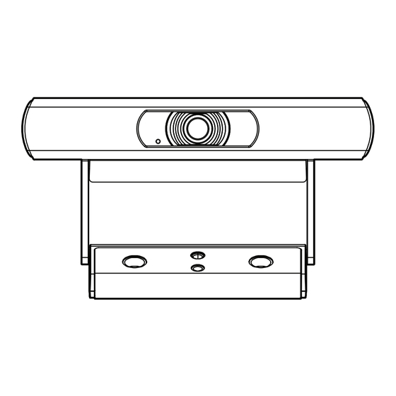
Connections and Controls (NC-110 ePTZ) Front Panel • Blinking Green: ID Mode • Solid Blue: Power On; Not Streaming • Solid Green: Streaming • Off: Camera is in Privacy Mode 2. Included Camera Mount: This product can be configured for monitor-mounting or surface-mounting. 3. - Page 9 Rear Panel Factory Reset Pinhole: Use a paperclip or similarly sized object to insert. Press and hold the reset button for 5 seconds. This resets all parameters to the factory defaults. 2. ID Button: Press to identify this product in Q-SYS Designer and Configurator. The STATUS LED on the front panel blinks green when in ID mode.
-
Page 10: Mounting To A Wall
Installation (NC-110 ePTZ) Mounting Above a Monitor Bend the bracket at the indicated pivot points shown to allow the optimal fit to the selected monitor. Mounting to a Wall 2 x Wall Screws TD-001654-01-A... - Page 11 Using the Existing Bracket for a Third-Party Mount 1/4-20 UNC Thread Use on various camera mounting brackets Attach the third-party mount to one of the 1 /4 -20 mounting holes on the included bracket. Removing the Existing Bracket for a Third-Party Mount On the bottom side of the camera, remove the two screws on the bracket.
- Page 12 2. Slide the bracket off the camera. 3. Mount the camera to the third-party mount. 1/4-20 UNC Thread Use on various camera mounting brackets // DO NOT REMOVE \\ Screws in block or camera TD-001654-01-A...
- Page 13 Installing Privacy Cover Peel adhesive. 2. Center and attach to top of camera. 3. Press firmly to affix adhesive. TD-001654-01-A...
-
Page 14: Dimension Drawings
Dimension Drawings NC-12x80 & NC-20x60 PTZ 90 mm (3.5 in.) 3.25 mm 72 mm (2.8 in.) (0.13 in.) 220 mm PTZ With Lens Cap (8.7 in.) 244 mm (9.6 in.) 129 mm (5.0 in.) 151 mm (6.0 in.) 142 mm (5.6 in.) 2 mm 170 mm (6.7 in.) (0.08 in.) - Page 15 NC-110 ePTZ 76.61 mm 41.50 mm (3.0 in.) (1.6 in.) 109.0 mm 194.26 mm (4.3 in.) (7.6 in.) 34.00 mm (1.3 in.) 106.57 mm (4.2 in.) TD-001654-01-A...
-
Page 16: Customer Support
© 2021 QSC, LLC. All rights reserved. QSC, the QSC logo, Q-SYS, and the Q-SYS logo are registered trademarks of QSC, LLC, in the U.S. Patent and Trademark office and other countries. Q-LAN and Q-SYS Designer are trademarks of QSC, LLC. Patents may apply or be pending.
Need help?
Do you have a question about the Q-SYS NC Series and is the answer not in the manual?
Questions and answers