Table of Contents
Advertisement
Quick Links
Advertisement
Table of Contents

Summary of Contents for APlusLift HW-SL6600X
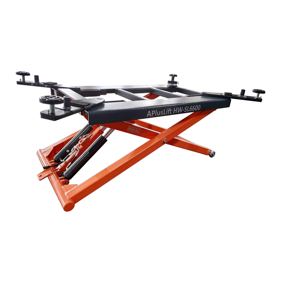
- Page 1 Model No. APlusLift HW-SL6600 Installation, Operation Short Platform Scissor Lift and Parts Manual Mid Rise Lifting Capacity, 6600 lbs. Distributed by Please read this entire manual carefully and completely before installation or operation of the lift. Date: 13.04.2018 05.06.2020...
- Page 2 Installation, Operation and Parts Manual A PlusLift HW-SL6600 X APlusLift HW-SL6600...
-
Page 3: Table Of Contents
Installation, Operation and Parts Manual A PlusLift HW-SL6600 X APlusLift HW-SL6600 SAFETY NOTES ........................................4 1.1 Operation of lifting platforms ..................................4 1.2 Checking of the lifting platforms ..................................4 1.3 Important safety notices ....................................5 1.4 Potential safety risks ....................................... 6 1.5 Noise level ........................................ -
Page 4: Safety Notes
Installation, Operation and Parts Manual A PlusLift HW-SL6600 X APlusLift HW-SL6600 SAFETY NOTES 1.1 Operation of lifting platforms This lift is specially designed for lifting motor vehicles. Users are not allowed to use it for any other purposes. The applicable national regulations, laws and directives must be observed. -
Page 5: Important Safety Notices
Installation, Operation and Parts Manual A PlusLift HW-SL6600 X APlusLift HW-SL6600 An expert is somebody with the training and experience required to possess specialist knowledge of lifting platforms and who is sufficiently familiar with the pertinent national work safety regulations, accident prevention regulations and generally acknowledged rules of engineering to be able to check and give an expert option on lifting platforms. -
Page 6: Potential Safety Risks
Installation, Operation and Parts Manual A PlusLift HW-SL6600 X APlusLift HW-SL6600 1.4 Potential safety risks 1.4.1 Mains voltage nsulation damage and other faults may result in accessible components being live Safety measures: Only ever use the power cord provided or a tested power cord. -
Page 7: Packing, Storage And Transportation
Installation, Operation and Parts Manual A PlusLift HW-SL6600 X APlusLift HW-SL6600 PACKING, STORAGE AND TRANSPORTATION Packing, lifting, handling, transporting operations must be performed only by experienced personnel with appropriate knowledge of the lift and after reading this manual. 2.1 The lift was dismantled into the following 2 parts for transportation... -
Page 8: Product Descriptions
Installation, Operation and Parts Manual A PlusLift HW-SL6600 X APlusLift HW-SL6600 PRODUCT DESCRIPTIONS 3.1 General descriptions This is chassis supporting lift for road vehicles. Its mobile design making the lift be able to move easily in your workshop when it is unloaded. -
Page 9: Installation Instructions
Installation, Operation and Parts Manual A PlusLift HW-SL6600 X APlusLift HW-SL6600 INSTALLATION INSTRUCTIONS 4.1 Preparations before installation 4.1.1 Space requirements Refer to 3.3 for the dimensions of the lift. There must also be a clearance of at least 1 meter (about 39”) between the lifting platform and fixed elements (e.g. -
Page 10: Installation Attentions
Installation, Operation and Parts Manual A PlusLift HW-SL6600 X APlusLift HW-SL6600 4.1.4 Checking parts Unfold the package and check if any parts missed as per the following list. Do not hesitate to contact us in case any parts missed. Name... -
Page 11: General Installation Steps
Installation, Operation and Parts Manual A PlusLift HW-SL6600 X APlusLift HW-SL6600 4.3 General Installation Steps Step 1: Remove the packaging and take the mechanical and hydraulic assembly to the designated installing place. Please do read and understand this manual thoroughly before next step. - Page 12 Installation, Operation and Parts Manual A PlusLift HW-SL6600 X APlusLift HW-SL6600 Step 4: Connect the oil hose. Connect the fitting of oil hose with its tie-in on the hydraulic block. Step 5: Connect external power supply.
- Page 13 Installation, Operation and Parts Manual A PlusLift HW-SL6600 X APlusLift HW-SL6600 Step 6: Fill with hydraulic oil. ONLY CLEAN AND FRESH OIL ONLY .Lift must be fully lowered before changing or adding hydraulic oil. Pour 6 liters (1.6 US gal.) anti-abrasion hydraulic oil into the oil tank.
-
Page 14: Items To Be Checked After Installation
Installation, Operation and Parts Manual A PlusLift HW-SL6600 X APlusLift HW-SL6600 4.4 Items to be checked after installation. Check items Rising speed 9/16”/s; 75db; Mechanical locks can engage and release effectively. If the control button works as “hold to run”? -
Page 15: Operation Instructionsly T
Installation, Operation and Parts Manual A PlusLift HW-SL6600 X APlusLift HW-SL6600 5.3 Operation instructions nel to Only use this lift on a surface that is stable, level and dry and not slippery, and capable of sustaining the load. To avoid personal injury and/or property damage, permit only trained personnel to operate the lift. -
Page 16: Trouble Shooting
Installation, Operation and Parts Manual A PlusLift HW-SL6600 X APlusLift HW-SL6600 TROUBLE SHOOTING ATTENTION: If the trouble could not be fixed by yourself, please do not hesitate to contact us for help .We will offer our service at the earliest time we can. By the way, your troubles will be judged and solved much faster if you could provide us more details or pictures of the trouble. -
Page 17: Maintenance
Installation, Operation and Parts Manual A PlusLift HW-SL6600 X APlusLift HW-SL6600 MAINTENANCE Easy and low cost routine maintenance can ensure the lift work normally and safely. Follow the below routine maintenance schedule with reference to the actual working condition and frequency of your lift. -
Page 18: Annex 1, Electrical Schemes And Parts List
Installation, Operation and Parts Manual A PlusLift HW-SL6600 X APlusLift HW-SL6600 Annex 1, Electrical schemes and parts list Pos. Code Name Specification 320205003 Motor 110V-1.5kW-1PH-60HZ-4P 320901014 AC contactor CJX2-1210/AC110 320401011 Button AR22F0R-10-W 321204021 AC motor protector NS2-32 321204020 Water-proof box... -
Page 19: Annex 2, Hydraulic Schemes And Parts List
Installation, Operation and Parts Manual A PlusLift HW-SL6600 X APlusLift HW-SL6600 Annex 2, Hydraulic schemes and parts list 1.oil tank 2.oil sucking filter 3.gear pump 4.coupling 5.motor 6.composite hydraulic block 7.cushion valve 8.overflow valve 9.single way valve 10.manual unloading valve 11.flow control valve... - Page 20 Installation, Operation and Parts Manual A PlusLift HW-SL6600 X APlusLift HW-SL6600 POS. Code Name Specification Power unit 1.5kW 624001064 Rubber oil hose L=3500mm, 615033012 Cylinder 2 SL6600-A05-B01 310101010 Straight connector G1/4---G1/4 624001847 Rubber oil hose L=200mm 615006003 Three way connector...
- Page 21 Installation, Operation and Parts Manual A PlusLift HW-SL6600 X APlusLift HW-SL6600 POS. Code Name Specification 330405014 Oil tank 330101004 Hydraulic block YF-2 330304001 Overflow valve EYF-C...
- Page 22 Installation, Operation and Parts Manual A PlusLift HW-SL6600 X APlusLift HW-SL6600 POS. Code Name Specification 330302001 Single way valve DYF-C 330305002 Throttle valve TC-VF 207103019 Composite washer 330301001 Cushion valve HZYF-C1 202109064 Screw M6*30 320201308B Gear pump CBK-F216-G 310101003 Straight connector M14*1.5-G1/4...
-
Page 23: Annex 3, Mechanical Exploded Drawings And Parts List
Installation, Operation and Parts Manual A PlusLift HW-SL6600 X APlusLift HW-SL6600 Annex 3, Mechanical exploded drawings and parts list POS. Name Specification POS. Code Name Specification 1 Welded arm A SL6600X-A01-B01 614033004B Welded arm A SL6600-A01-B01 2 Welded arm B... - Page 24 Installation, Operation and Parts Manual A PlusLift HW-SL6600 X APlusLift HW-SL6600 POS. Name Specification POS. Code Name Specification 15 Bearing 252850 612033001 Lifting tray SL6600-A03-B03-C01 16 Flat washer C Ø28 410330573 Lifting pad holder SL6600-A03-B06-C01 17 Hex Locking nut 612033002B...
- Page 25 Installation, Operation and Parts Manual A PlusLift HW-SL6600 X APlusLift HW-SL6600 POS. POS. Code Name Name Specification Specification 614033001B Support bracket SL6600-A06-B01 1 Trolley SL6600X-A01-B30 614033002 Handle SL6600-A06-B02 2 Wheel Ø93X62 420330060 Nylon wheel SL6600_M90X43 3 Screw nut Power unit 110V-1PH-60HZ-1.5KW...
Need help?
Do you have a question about the HW-SL6600X and is the answer not in the manual?
Questions and answers