TGS WP-EWG-040U Manual
Emergency inverter
Hide thumbs
Also See for WP-EWG-040U:
- Manual (14 pages) ,
- Installation and operation instructions manual (6 pages)
Table of Contents
Advertisement
Quick Links
EMERGENCY INVERTER
WP-EWG-040U | for LED High Bay Lights
General Description
The Emergency Inverter for LED High
Bay Lights, listed for field and factory
installation, provides constant power
output to the load during emergency
mode operation. They maintain
illumination in the emergency mode for
a minimum of 90 minutes. It is an ideal
emergency solution for Round/Circular
LED high bay fixtures.
Features and Benefits
• Constant power output
• Universal input range
• Integrated junction box design
• Field and factory installation
• IP65 for dry, damp and wet location
• 40W & 90mins durable emergency
operating time
• Surge L-N:3KV; L&N-PE:3KV
• Protection: Over-Voltage ,Short-Circuit,
Over-Load, Open-Circuit
1
• LiFePO4 safety batteries
• Link to the input of LED drivers
• High PF even during charging
• Safety rope prevent from dropping while
installation
• Remote test from a handheld controller
• Self-diagnostic every month and year
• RoHS compliant
• 5 years warranty
:9601 Variel Ave. Chatsworth, CA 91311
:info@trulygreensolu�ons.com
BC
Self
Diagnostic
:818-206-4404
:www.trulygreensolu�ons.com
Advertisement
Table of Contents

Related Manuals for TGS WP-EWG-040U


Summary of Contents for TGS WP-EWG-040U
- Page 1 EMERGENCY INVERTER WP-EWG-040U | for LED High Bay Lights General Description The Emergency Inverter for LED High Bay Lights, listed for field and factory installation, provides constant power output to the load during emergency mode operation. They maintain illumination in the emergency mode for a minimum of 90 minutes.
-
Page 2: Ordering Information
Ordering Information Model Output Voltage Related Output Power Battery Capacity Emergency Time WP-EWG-040U 120-200 Vdc 40 W 96 WH 90 mins Input Characteristics Parameter Min. Typical Max. Remarks Rated Input Voltage (Vac) Input Voltage Range (Vac) Input Frequency Range (Hz) 50/60 Max. -
Page 3: Protection Characteristics
Battery Characteristics Name Parameter Battery Type LiFePO4 Battery Capacity 6000mAh/16V 96WH Charging Time (H) 24 Hours Max. Charging Interval (M) 12 Months Protection Characteristics Typica Parameter Status Min. Max. Remarks Over-Voltage Protection (V) ● Short-Circuit Protection (mA) Power Off ● Open-Circuit Protection (mA) Abnormal Indicator Light ●... -
Page 4: Other Characteristics
Other Characteristics Parameter Min. Typical Max. Condition Lifetime (H) 50000 277Vac, Ta 25℃ MTBF (H) 200000 (MIL-HDBK-217F) Max. Installation Height (ft) Weight (g) 3550 3700 3850 Dimension (Inch) L4.92*W4.92*H11.22 Excluding the ring and hook Remarks: If not specified, all the above parameters are measured in the full load state of the product at Ta 25℃. Safety Regulation Approval Certificate... -
Page 5: Electromagnetic Compatibility
Electromagnetic Compatibility EMI/EMS Items Standards Judgement Basis Conduction CE FCC Part 15 Class B Radiation RE FCC Part 15 Class B Harmonic Wave IEC/EN 61000-3-2 Class C Surge UL924 L-N :3KV/2Ω,L&N-PE:3KV/2Ω Ring-wave ANSI C62.41 2.5KV/2Ω Safety Test Projects Safety Test Technical Requirements Condition Input-Ground... - Page 6 Structure UL1015 18AWG Green 152mm INPUT OUTPUT AC-N UL1015 18AWG White 152mm AC-L Un-Switch UL1015 18AWG Black 152mm AC-L Output AC-N AC-L Wall Switch UL1015 18AWG White in Black 152mm AC-L Un-Switch AC-N Output LE D AC-L Output UL1015 18AWG Blown 152mm DIMMING AC-L Wall Switch Emergency...
-
Page 7: Diagnostic System
Indicator Parameter Remarks Solid Green ON System OK/AC OK System NG, battery voltage is too low, None LED Off LED fixture is Short Battery not detected, check battery connection Flashing Green (1s on, 1s off, cycling) The Emergency inverter working in Flashing Green (0.1s on, 5s off, cycling) Emergency mode Discharge time is less than 90 minutes... -
Page 8: Wiring Diagram
Wiring Diagram :9601 Variel Ave. Chatsworth, CA 91311 :818-206-4404 :info@trulygreensolu�ons.com :www.trulygreensolu�ons.com... - Page 9 Wiring Diagram :9601 Variel Ave. Chatsworth, CA 91311 :818-206-4404 :info@trulygreensolu�ons.com :www.trulygreensolu�ons.com...
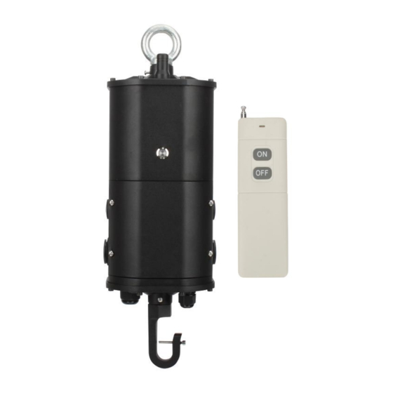
- Page 10 Installation Guideline ① Hanging ring bolt ② Thread mounted hole ③ AC input wire protective tube ⑥ ④ Dimming wire protective tube ⑤ Integrated junction box cover ⑥ Safety rope ⑦ LED Driver dimming wire ⑧ LED Driver input wire ⑨...
- Page 11 Installation Guideline Step One: Disconnect AC Power From Fixture Disconnect all power source to the lighting fixture and ensure they are locked out during installation or maintenance. The AC driver must be source from the emergency inverter. Select a suitable location for the emergency inverter an install such that its output leads can connect to the input leads of the AC driver.
-
Page 12: Remote Controller
Remote Controller • Diagnosis In the normal Charging Mode, after being charged for 12 hours or fully charged, dial the switch on the side(towards the antenna),pull out the antenna, press the button ON, then it will enter Manual Diagnostic Mode. Press OFF to exit. •... - Page 13 Light Output Calculation To ensure sufficient light output in the end application, please estimate by doing the following: a. Check the light efficacy(lm/w) of LED luminaire, which is provided by the luminaire manufacturer, test it directly, check the test data from 3rd party test laboratory like UL, ETL etc., visit a 3rd party public database (such as Design Lights Consortium, www.designlights.org etc.), or other comparable means.
- Page 14 Packaging Name Parameter Net Weight of 8.16 LB Singe Product Carton Size L14.57*W7.48*H13.38 Inch Qty./Ctn 2 PCS N.W./G.W of Carton 16.31 /18.08 LB Shipment • It is suitable for transportation by car, boat and airplane. • During transportation, it should be sheltered, sun-proof, and civilized loading and unloading.
-
Page 15: Important Safeguards
IMPORTANT SAFE GUARDS When using electrical equipment and this lighting device basic safety precaution should be followed at all times including but not limited to the following: PLEASE READ CAREFULLY AND FOLLOW ALL INSTRUCTIONS FOR YOUR OWN SAFETY WARNING: AC power must be turned off before proceeding with assembly or installation of emergency driver. IMPORTANT: For use with non-dimming LED fixtures up to 40W.
Need help?
Do you have a question about the WP-EWG-040U and is the answer not in the manual?
Questions and answers