Roland BK-5 Service Notes
Baking keyboard
Hide thumbs
Also See for BK-5:
- Owner's manual (152 pages) ,
- Brochure & specs (4 pages) ,
- System update (4 pages)
Table of Contents
Advertisement
Jan. 2012
TABLE OF CONTENTS
VIEW 2 - VIEW 3
VIEW 4 - VIEW 5
EXPLODED VIEW 2 - TOP CASE
How to Replace the NITTO ACETATE TAPE #5
on the Bottom Case and Speaker R/L
PARTS LIST BK-5
Copyright © 2012 by ROLAND CORPORATION
All rights reserved. No parts of this publication may be reproduced in any form whithout the written permission of
ROLAND CORPORATION.
3/6
7/9
10/11
12/13
20/21
22/23
24/27
29/41
42/43
44/45
SN00143
FIRST EDITION
2
9
CIRCUIT DIAGRAM (JACK B. 1/5)
14
15
16
17
CIRC. B. (LEFT PANEL BOARD, PHONES BOARD)
18
19
CIRC. B. (RIGHT PANEL BOARD+ENCODER B.)
28
28
29
K6018798
SERVICE NOTES
Issued by RES
Printed in Italy
BK-5
46/47
48/49
50/51
52/53
54
56/57
58/59
60/61
62
64/65
66/67
68
69/70
70
72/73
Advertisement
Table of Contents

Related Manuals for Roland BK-5


Summary of Contents for Roland BK-5
-
Page 1: Table Of Contents
29/41 BLOCK DIAGRAM 42/43 CIRCUIT BOARD (MAIN Board) 44/45 Copyright © 2012 by ROLAND CORPORATION All rights reserved. No parts of this publication may be reproduced in any form whithout the written permission of ROLAND CORPORATION. SN00143 K6018798 Printed in Italy... -
Page 2: Cautionary Notes
In the circuit diagram, “NIU” is an abbreviation for “NOT IN USE,” and “UnPop” is an abbreviation for “Unpopulated.” They both mean non mounted components. The circuit board and circuit board diagram show silk/screened indications, but no components are mounted. DIGITAL KEYBOARD BK-5 Series 074021E32 230V EU 230VE 074021E49 220V CN... - Page 3 BK-5 For EU countries For EU Countries For China For China For China...
- Page 4 Refer all servicing to your retailer, ....................the nearest Roland Service Center, or an authorized Roland dis- tributor, as listed on the “Information” page. • Never allow foreign objects (e.g., flammable material, ....................
- Page 5 When the BK-5 is turned off by the “Auto Off” function, the [POWER] button’s position doesn’t change, which means that you need to press it once, wait a few seconds, then press it again to switch the BK-5 back on.
- Page 6 The wire which is coloured BROWN must be connected to the terminal which is marked with the letter L or coloured RED. Under no circumstances must either of the above wires be connected to the earth terminal of a three pin plug. For the USA For the USA DECLARATION OF CONFORMITY Compliance Information Statement BK-5 Backing Keyboard...
-
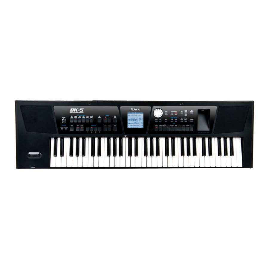
Page 7: Specifications
BK-5 SPECIFICATIONS Display type Display Graphic LCD, 160 x 160 dots, backlit Keyboard Keyboard 61 velocity sensitive keys Sound Source Max. Polyphony 128 voices (GM2/GS/XG Lite compatible) Sounds 1,172 tones 60 Drum Sets Multitimbral parts 3 keyboard parts (UP1, UP2, LWR) + 16 song parts Master Tuning 415.3~466.2 Hz... - Page 8 CD-ROM (Style Converter 4.0, USB driver) Options USB flash memory (M-UF-series) Pedals DP-series/BOSS FS-5U foot switch Roland EV-series expression pedal Note: In the interest of product improvement, the specifications and/or appearance of this unit are subject to change without prior notice.
-
Page 9: Disassembly
BK-5 Style Converter 4 system requirements Operating system Microsoft® Windows® XP Microsoft® Windows® Vista® * This does not work with the 64-bit edition of Windows Vista® Microsoft® Windows® 7 CPU/clock Pentium® Celeron® processor 1 GHz or higher 512 MB or more... -
Page 10: Location Of Controls
Jan. 2012 BK-5 LOCATION OF CONTROLS K2478469 RED S-KEYTOP BK-5 04452945 3.5MM JACK YKB21-5344N K2478456 S-KEYTOP SMALL 13449146 6.5MM JACK YKB21-5012G(W/SW) 01340290 PTR TACT SWITCH EVQ11A05R H=5,0 02232245 RCA(PIN) JACK YKC21-3661 K2478467 T S KEYTOP MD1H BLK 13449275 6.5MM JACK YKB21-5074... - Page 11 KIT ASSY RIGHT PANEL B.+ENCODER B. BK-5 K2268239 RIGHT SPONGE PANEL CUSHION BK-5 K2268238 LEFT SPONGE PANEL CUSHION BK-5 7782810000 KIT ASSY JACK BOARD + USB BOARD BK-5 04459190 USB CONNECTOR YKF45-0033N K2168129 SPACER PWB USB BK-5 BK-5 OR K2028178...
- Page 12 Jan. 2012 VIEW 2 When you need to replace the Left Panel B. with the new one please replace also two adhesive sponges # on the Pcb like in the picture. K2268242 VIEW 3 Peel off adhesive tapes #40122923 and fix cables over them. The 24P cable coming from Right Panel B.
- Page 13 BK-5 VIEW 4 When you need to replace the Encoder B. with the new one please replace also the rectangular black felt. Cut out the rectangular black felt from one of the “Felt Cushiun Speaker” and fix it over the Encoder board.
-
Page 14: Exploded View 1 - Top Case
3 pcs LF MET MUSIC REST HOLDER E-2 2 pcs ******** MUSIC REST BASE BLACK 04232978 1 pce MUSIC REST PLATE BK-5 BK-5OR 1 pce ******** K2248210 SPEAKER COVER L BK-5 K2248211 SPEAKER COVER R BK-5 K2228114 SPEAKER CUSHION BK-5... -
Page 15: Exploded - Bottom Case
5100005594 WOOFER X100DF65-00B 4OHM 20W Attention:When you replace the WOOFER with the new one see Change Information here below CHANGE INFORMATION On the BK-5 the “ WOOFER ” has been changed. BK-5 First production BK-5 From July production 5100028323 WOOFER 412-05033-02-01... -
Page 16: Keyboard Parts List
Jan. 2012 KEYBOARD PARTS LIST Part Code Part Name Description Q'ty 04344189 KEYBOARD ASSY MSK-2 61KEY (W/O CABLE) 03786378 NATURAL KEY C FOR MSK-2 03786389 NATURAL KEY D FOR MSK-2 03786390 NATURAL KEY E FOR MSK-2 03786401 NATURAL KEY F FOR MSK-2 03786412 NATURAL KEY G... -
Page 17: Wiring Diagram
BK-5 WIRING DIAGRAM ENCODER LEFT PANEL LCD MODULE RIGHT PANEL HOST 26FMN-SKT-A 24FMN-SKT-A S5B-PH-K-S W3 W2 CN10 CN14 CN12 CN11 B4P7-VH 26FMN-BKT-A B2B-PH-K-S 52030-1629 18FMN-BMTTN-A-TF B3B-PH-K-S 24FMN-BKT-A 18FMN-SMT-A B5B-PH-K-S MIDI JACK BOARD MAIN BOARD B6B-PH-K-S 6501S-26GS2 PITCH BENDER LEFT SPEAKER... -
Page 18: How To Replace Cable #7782814000
How to replace cable #7782814000 Note: If you have to change “Cable #7782814000” we suggest to order also “SPONGE CUSHION SPEAKER CABLES BK-5/OR #K2268241” 1) Wrap the cable with their sponge cushions speaker cables as showed here under : START FROM HERE 2) Solder the cables onto the Right and Left speakers #04125312 3) Place the Right and Left Speakers and place the cable through the cut on the felt.cushion. - Page 19 BK-5 4) Add hot melt between the cable and speaker box slot (right and left side). 5) Bend down the cable with 90° angle and then place the cables in the clearance between the speaker boxes and the rear side of bottom cabinet.
- Page 20 Jan. 2012 How to replace the ADHESIVE FELT and NITTO ACETATE TAPE #5 code #40122612 on Bottom Case and Speaker box R / L When you substitute the BOTTOM CASE #04017645 you must replace also the code #K2248209 SHORT ADHESIVE FELT MM 290x10 TH. 1 as showed here under : adhesive felt NOTE:...
- Page 21 BK-5 adhesive felt When applying black felt #K2248208 respect the refererence mark. Apply the acetate tape along the whole profile of the Left and Right Speaker Boxes. Chek adhesion on corner.
-
Page 22: Parts List
PLASTIC TOP CASE BK-5 04017645 BOTTOM CASE K2218119 PANEL SHEET L BK-5 K2218120 PANEL SHEET R BK-5 K2218121 PANEL SHEET LCD BK-5 BK-5OR K2248210 SPEAKER COVER L BK-5 K2248211 SPEAKER COVER R BK-5 KNOB BUTTON 12499175 JSPUE0011A KNOB ON-OFF BUTTON... - Page 23 MAIN PCB ASSY BK-5 7782808000 KIT ASSY LEFT PANEL B.+PHONES BOARD BK-5 7782809000 KIT ASSY RIGHT PANEL B.+ENCODER B. BK-5 7782810000 KIT ASSY JACK BOARD + USB BOARD BK-5 J5259192 I.C. TC74VHC138FT(EL) FLAT IC18,IC19 on Jack B. 02455212 IC (CUSTOM) S1L50282F32H200(KSM) KEY SCA IC10 on Jack B.
- Page 24 REINFORCE BAR K2338102 SPEAKER BOX R K2338103 SPEAKER BOX (L) 5100009656 DC PLUG SUPPORTER K2168129 SPACER PWB USB BK-5 BK-5 OR J2289326 NUT HEX AX-SYNTH 529-08028-01-00 K2138132 WASHER PLAIN ID3.3xOD6.0xT0.3 BZC K2138133 WASHER SPRING ID3.3xOD5.5xT0.9 BZC J2139140 WASHER PLAIN 3.5X10X1 MS 519-12351-00-10 40122923 DOUBLE FACED ADH NITTO NO.501F W20MM 20M...
- Page 25 BK-5 04236112 SWITCHING ADAPTER PSB-7U (S) 01903356 AC CORD SET 230V 1.0M FOR PSB (only for 230V) 5100000115 AC CORD SET 230V 1.0M FOR UK (PSB) (only for 230VE) 02562456 AC CORD SET 120V 1.0M (NON POLAR) (only for 117V U-117V U/CS)
-
Page 26: Verifying The Version Numbers
The following screen will show the Version number. Performing a Factory Reset The following function allows you to recall the BK-5 original factory settings. This has no effect on the data stored on a USB memory. You can carry out a factory reset in two ways: A. -
Page 27: Updating The System
4. Keeping the [WRITE] button pressed, power on the BK-5 . Hold the WRITE Button until the “Update Mode:” text appears on the top line of the LCD of BK-5. 5. Wait until the end of the update; the display will show “SUCCESS “. - Page 28 PSB-7U CH1 = L CH2 = R Entering the Test Mode Keeping the [VARIATION 4], [INTRO] and [ENDING] buttons pressed, power on the BK-5 . Wait until “Version” test is displayed. Exiting the Test Mode Turn the power off. Moving (forced) between Test Items To skip to the next test item: keep the [POP ROCK] button pressed and then press TEMPO [+] button.
- Page 29 BK-5 2. Switch and LED check The display shows: The display will show the switch to press and the LED associated to it will blink. For each switch pressed the relative LED will be lit. At the end of the sequence the test will automatically go to the next test The display shows: The display will show the switch to press and the LED associated to it will blink.
- Page 30 7. Press the DP-8 Pedal and verify that the display shows “Switch: ON”. 8. Release the DP-8 Pedal and make sure the display shows “Switch: OFF OK”. 9. Remove the DP-8 Pedal and connect the EV-5 pedal to BK-5 PEDAL SWITCH/EXPRESSION input. EV-5 10.
- Page 31 1. Connect the MIDI cable between BK-5 MIDI IN and MIDI OUT. 2. Verify that the display shows “Connected”. 3. Disconnect the MIDI cable from BK-5 MIDI IN and MIDI OUT and verify that the display shows “Disconnected OK”. 4. Press [START/STOP] button to go to next test.
- Page 32 8. USB MEMORY check The display shows: 1. Connect the USB Memory (like ROLAND M-UF2G) to USB MEMORY socket. 2. Verify that the display shows : USB MEMORY “Connected” and READ/WRITE: OK. 3. Remove the USB Memory and make sure the display shows: USB MEMORY “Disconnected OK”.
- Page 33 BK-5 10. Video out check The display shows: Press the following two switches and check the related external Monitor images as follows: Image in Image in NTSC format PAL format Note: The two image types (NTSC or PAL) are almost the same. The only difference is that the PAL type is a little bit squashed than the NTSC type, so carefully check this difference.
- Page 34 Jan. 2012 12. Speakers check 12.1 Speakers separation check The LCD display shows: 1. Check the sound (1Khz Sine wave) coming out only from Left Speaker with right intensity according to VOLUME position. 2. Press the switch ENTER; the LCD display shows: 3.
- Page 35 13. Phones socket check The display shows: Setting: Connect the BK-5 PHONES to oscilloscope’s CH1-CH2 inputs (by means of a STEREO AUDIO CABLE). Press one by one [VARIATION 1] [VARIATION 2] [VARIATION 3] buttons and check the following values on the oscilloscope:...
- Page 36 14. Output L/R sockets check The display shows: Setting: Connect the BK-5 OUTPUT L/R to oscilloscope’s CH1-CH2 inputs (by means of 2x Mono Audio cables). 1. Press [VARIATION 1] button. Check the following values on the oscilloscope: OSCILLOSCOPE SETUP: Volt div. = 5.00V/ Time div. = 1.00ms CH1 = OUTPUT LEFT It must be 1000hz (±...
- Page 37 5. Press [START/STOP] button to go to next test. 15. Audio Input socket check The display shows: Setting: • Connect the n.2 Mono Audio Cables from BK-5 EXT INPUT to the Waveform generator. • Connect the BK-5 OUTPUT L/R to oscilloscope’s CH1-CH2 inputs. Wave generator n.1 Measure...
- Page 38 1. Produce following wave with external Waveform generator: Wave generator OUT L: Freq =1Khz (sine wave) Amplitude=2,5Vpp (measured with cable not connected to BK-5) Wave generator OUT R: Freq =1Khz (sine wave) Amplitude=2,5Vpp (measured with cable not connected to BK-5) 2.
- Page 39 18. Factory Reset and Auto Power off check. The display shows: 1. Press [WRITE] button to execute the Factory Reset. 2. At the end the display shows: 3. Press [ENTER] button and verify that the BK-5 will be switched off.
-
Page 40: Block Diagram
Jan. 2012 BK-5 BLOCK DIAGRAM ENCODER BOARD WIRING 3-PIN RIGHT PANEL LEFT PANEL FFC 26 pin FFC 24 pin 1.00 mm pitch 1.00 mm pitch USB HOST MODULE CN10 CN12 JACKBOARD LED&SWITCH SCAN LED DATA IC18,19 TC74VHC138FT SWITCH DATA BL-PWM... -
Page 41: Circuit Board (Main Board)
Jan. 2012 CIRCUIT BOARD (MAIN Board) fig.b-main-1.eps... - Page 42 BK-5...
-
Page 43: Circuit Diagram (Main B. 1/2)
Jan. 2012 BK-5 CIRCUIT DIAGRAM (MAIN B. 1/2) R151 YA16 R152 UnPop D3.3V R153 YA14 DGND D3.3V D3.3V 0.1uF D3.3V DGND AUDCK DQ15 YA16 DQ14 EXB28V470JX RA40 AUDATA0 UnPop DQ13 DQ15/A-1 AUDCK CA22/AHP6 EXB28V470JX RA37 RA58 A10/AP DQ12 DQ14 EXB28V103JX... -
Page 44: Circuit Diagram (Main B. 2/2)
Jan. 2012 BK-5 CIRCUIT DIAGRAM (MAIN B. 2/2 ) UnPop LED1 UnPop D3.3V C137 D3.3V C136 UnPop 0.1uF 0.1uF SML-310LTT86 B3B-PH-K-S (LF)(SN) UnPop DGND DGND SYNC _SYNC/AHP15 WBREQ/WAHH6 ECKUDL WA26 RA51 EXB28V330JX WBACK/WAHH7 XLDBE WA24 WA26 SD4/_WCS0 UOVCD XWCS1 WA23... -
Page 45: Circuit Board (Jack B., Usb Board)
Jan. 2012 BK-5 CIRCUIT BOARD (JACK B., USB BOARD) -
Page 46: Circuit Diagram (Jack B. 1/5)
Jan. 2012 BK-5 CIRCUIT DIAGRAM (JACK B. 1/5) C342 100nF C343 100nF C335 100nF ADPV A +3V3 100nF C334 100nF NOISE REDUCTION C333 100nF Low ESR 25V 470uF C337 100nF C318 100nF ECJ3YB1E106K 1206 C336 100nF C319 100nF 470uF Low ESR 25V... - Page 47 Jan. 2012 CIRCUIT DIAGRAM (JACK B. 2/5) +5VD C138 100nF D+3.3 C139 100nF +5VD C140 100nF C141 100nF C142 100nF C143 100nF R131 R132 KSMTXD KSMTXD +5VD MK17 SC17 BR17 PR17 MK16 SC16 BR16 PR16 MK15 SC15 BR15 PR15 MK14 SC14 BR14 PR14...
- Page 48 BK-5...
-
Page 49: Circuit Diagram (Jack B. 3/5)
Jan. 2012 BK-5 CIRCUIT DIAGRAM (JACK B. 3/5) DA2J10100L R147 R148 R149 ADPV SW1A R150 PWL-2P2T-6SBPA VADP C165 R152 C166 R151 C170 220K TPC8125,LQ C167 C168 C169 100nF SW1B 470uF 470uF 470uF PWL-2P2T-6SBPA D1FM3-5053 C171 SC-03-10G HEC0470-01-640 10nF R153 C172... -
Page 50: Circuit Diagram (Jack B. 4/5)
Jan. 2012 BK-5 CIRCUIT DIAGRAM (JACK B. 4/5) R223 R224 +5VLED WRITE +5VD SSD0 R218 LSD7 SSD1 R219 SSD2 R220 C223 100nF C224 100nF +5VD +5VLED SSD3 R221 R228 10 RN2426 LLS7 SSD4 R222 SSD5 R229 +5VLED IC17 C230 C231... -
Page 51: Circuit Diagram (Jack B. 5/5)
Jan. 2012 BK-5 CIRCUIT DIAGRAM (JACK B. 5/5) D+3.3 R341 R342 CLOCKOUTEN R343 PWRSVE R344 R345 PCLK R346 R347 R348 SCLK R349 C270 100uF D+3.3 C280 D1R5V_TV A3R0_TV A3R0_TV C301 DA204U C323 100nF JK9A PCLK R350 FSLM2520-1R8J YKC21-3661 PCLK BOUT... -
Page 52: Circuit Diagram (Usb B.)
Jan. 2012 CIRCUIT DIAGRAM (USB B.) S-BOARD (CN2) ACM2012-900-2PT S5B-PH-K-S YKF45-0033N 0ohm 10uF... - Page 53 BK-5...
- Page 54 Jan. 2012 BK-5 CIRCUIT BOARD (LEFT PANEL BOARD, PHONES BOARD)
-
Page 55: Circuit Diagram (Left Panel B.)
Jan. 2012 BK-5 CIRCUIT DIAGRAM (LEFT PANEL B.) LLS0 LLS1 LLS2 LLS3 LHR3EC041 LHR3EC041 LHR3EC041 LHR3EC041 EVQ QJJ05Q EVQ QJJ05Q EVQ QJJ05Q EVQ QJJ05Q LLS4 LLS5 POP/ROCK DISCO DANCE JAZZ BLUES BALL ROOM POP/ROCK DISCO DANCE JAZZ BLUES BALL ROOM... -
Page 56: Circuit Diagram (Phones Board)
Jan. 2012 CIRCUIT DIAGRAM (PHONES BOARD) YKB21-5078 SBT-0460 YKB21-5078 SBT-0460 JACK BOARD (CN2) SBT-0460 S6B-PH-K-S SBT-0460... - Page 57 BK-5...
-
Page 58: Circuit Diagram (Encoder B.)
BK-5 Jan. 2012 CIRCUIT BOARD (RIGHT PANEL BOARD+ENCODER B.) CIRCUIT DIAGRAM (ENCODER BOARD) ENC1 EVEGC1F2024B JACKBOARD (CN12) S3B-PH-K-S COMM... -
Page 59: Circuit Diagram (Right Panel Board)
Jan. 2012 BK-5 CIRCUIT DIAGRAM (RIGHT PANEL BOARD) LLS0 LLS1 LLS2 LLS3 LHR3EC041 LHR3EC041 LHR3EC041 LHR3EC041 EVQ11A05R EVQ11A05R EVQ11A05R EVQ11A05R LLS4 LLS5 ENTER LIST WRITE ENTER LIST TRACK MUTE LHR3EC041 LHR3EC041 LHR3EC041 LHR3EC041 EVQ11A05R EVQ11A05R EVQ11A05R EVQ11A05R TRACK MUTE USB MEMORY...
Need help?
Do you have a question about the BK-5 and is the answer not in the manual?
Questions and answers