Cima Plus Operation And Maintenance Instructions
Hide thumbs
Also See for Plus:
- Operation and maintenance instructions (64 pages) ,
- Maintenance instruction (42 pages)
Table of Contents
Advertisement
Quick Links
Advertisement
Table of Contents

Related Manuals for Cima Plus


Summary of Contents for Cima Plus
- Page 1 PLUS OPERATION AND MAINTENANCE INSTRUCTIONS ® Atomizzatori e Impolveratori...
- Page 2 ! Our first goal, is to get our Customers happy for having met us! The “Spare parts catalogue” of this sprayer/sprayhead is available in the ‘“restricted area” on website www.cima.it. In order to accede, use: User name: sprayer Password: 844719KE...
- Page 3 PRIVATE PROPERTY. ANY REPRODUCTION, EVEN IF PARTIAL, IS FORBIDDEN IF NOT PREVENTIVELY AUTHORIZED IN WRITING BY THE CIMA S.P.A. COMPANY. CIMA S.p.A. - 27040 Montù Beccaria - Loc. Molino Quaroni - (PV) - ITALIA Tel. +39.0385.246636 r.a. - Fax +39.0385.246637 http://www.cima.it...
- Page 5 Plus 42 - 45 - 50 - 55 LISTING OF VALID PAGES This publication consists of pages, subdivided as follows: N° OF PAGE REVISION BASE from I to VI March 2012 from 1 to 77 March 2012 ADDITIONAL RECORDS AND VARIANTS...
-
Page 6: Table Of Contents
Plus 42 - 45 - 50 - 55 GENERAL INDEX FOREWORD ..........................1 CHECKS TO BE CARRIED OUT AT MATERIAL RECEPTION ........... 1 PUBLICATION IDENTIFICATION ....................1 ATTACHED PUBLICATIONS ....................1 PURPOSE OF PUBLICATION ....................1 REFERENCE TO REGULATIONS ..................... 2 USING THE MANUAL ...................... - Page 7 Plus 42 - 45 - 50 - 55 COUPLING MODALITIES ....................30 HITCHING TO THE TRACTOR ....................30 MOUNTING OF CARDAN TRANSMISSION SHAFT ............... 31 INSTALLATION OF REMOTE CONTROLS ................32 5.3.1 Manual 2-tap distributor - P9 ....................32 5.3.2 Electrical control panel - E10 ....................32 5.3.3.
- Page 8 Plus 42 - 45 - 50 - 55 13.2 FAN SHAFT SUPPORT OIL LEVEL CHECK ................55 13.3 FAN SHAFT SUPPORT OIL REPLACEMENT ................. 55 13.4 CLEANING OF FILTER’S CARTRIDGE ................... 56 13.5 PURGING OF RESIDUES FROM FILTER ................56 13.6...
-
Page 9: Foreword
Plus 42 - 45 - 50 - 55 FOREWORD 1.1 - CHECKS TO BE CARRIED OUT AT MATERIAL RECEPTION At reception of the machine, make sure that this one is complete and in good condition in every part. If any damaged parts are found out, timely inform about that the machine Distributor, or directly contact C.I.M.A. -
Page 10: Reference To Regulations
Plus 42 - 45 - 50 - 55 1.5 - REFERENCE TO REGULATIONS This manual was set out conforming to the regulations contained in following documents: — Directive 2006/42/CE: Attachment 1 point 1.7.4; — UNI 10653: Technical Documentation; — UNI 10893: Technical Documentation. -
Page 11: Glossary
Plus 42 - 45 - 50 - 55 GLOSSARY 2.1 - TERMINOLOGY The terms FRONT, REAR, RIGHT and LEFT utilised in this publication refer to the sprayer as seen by an operator from behind the operative unit along the drive line and facing it: the rear part of the machine is that closest to the operator, and is where the distribution device (Head) is mounted - and the front part is the one that gets attached to the tractor. - Page 12 Plus 42 - 45 - 50 - 55 Safety decals - STOP THE ENGINE AND REMOVE THE KEY FROM THE TRACTOR’S CONTROL PANEL BEFORE CARRYING OUT ALL MAINTENANCE OR REPAIR OPERATIONS - CONSULT THE USER AND MAINTENANCE MANUAL BEFORE USING OR INTERVENING ON THE MACHINE...
- Page 13 Plus 42 - 45 - 50 - 55 - WARNING: NEVER OPERATE - INDICATION OF THE 2,5 atm THE SPRAYER WITHOUT LIQUID WHEELS OPERATING IN THE TANK PRESSURE (accessory) 95056 95065 95056 - INDICATION ON THE - HOOKING POINT OPERATION OF THE...
- Page 14 Plus 42 - 45 - 50 - 55 For version with fan switching-off device 95065 95102 95015 (*) 50 Plus 2000 95010 95001 FREE WHEEL For models on which it is forseen 95009 95054 (*) 01213 95009 FAN SHAFT BEARINGS...
-
Page 15: General Information
Plus 42 - 45 - 50 - 55 GENERAL INFORMATION 3.1 - MACHINE IDENTIFICATION 00070 Identification nameplate 00128 3.2 - TECHNICAL ASSISTANCE C.I.M.A. S.p.A. is at the complete disposal of customers for any type of intervention. The names and addresses of its service network, both in Italy and in foreign countries, can be requested from: C.I.M.A. -
Page 16: Precautions Against The Fires
Plus 42 - 45 - 50 - 55 It is necessary to scrupulously abide by the following general norms: — check that the power of the tractor is compatible with the sprayer to be used; — verify that the maximum weight admitted on the three-point hoister of the tractor is compatible with the weights of the sprayer to be used;... -
Page 17: Safety Systems
Plus 42 - 45 - 50 - 55 3.4 - SAFETY SYSTEMS All machine moving parts are suitably protected by guards and highlighted through the use of warning decals. - It is forbidden to use the machine with these guards removed. -
Page 18: Storage
Plus 42 - 45 - 50 - 55 To use pesticides (purchase, transport, loading, treatment planning, mixture preparation, field transfert, treatment performance, ending treatment liquid waste management, equipement rinsing and waste disposal) you must follow the country rules. Absolutely respect the rules on the label of the product used referring to the dose for hectar and to the compatibility of other products. -
Page 19: Personal Means Of Protection
Plus 42 - 45 - 50 - 55 Empty packaging and contaminated containers to be done away with cannot be dispersed, burned or buried. The washing water for the cisterns and the tools utilised for the preparation of mixtures cannot be emptied on the ground, spilled into the sewage system or in waterways and rivers. -
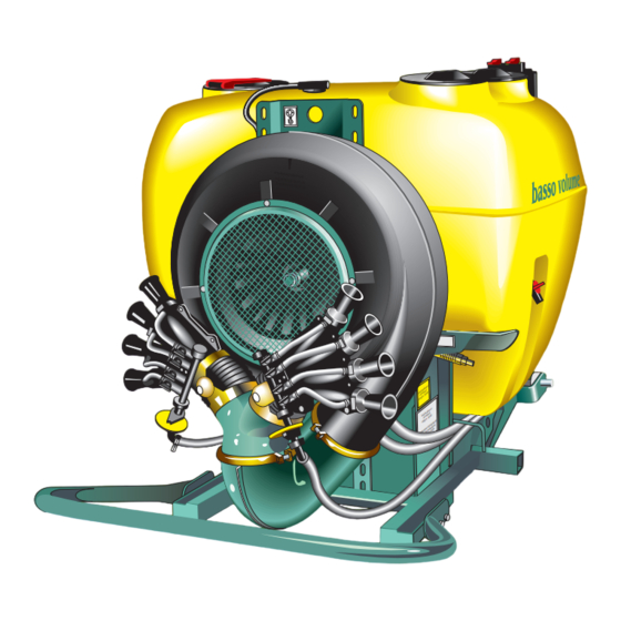
Page 20: Machine Structural Analysis
Plus 42 - 45 - 50 - 55 MACHINE’S STRUCTURAL ANALYSIS The pictures indicate the position of the main components of the sprayer. RINSING MAIN FILLER (BP) TANK (for the models where it is TANK foreseen) CENTRIFUGAL ELECTRICAL DISTRIBUTOR (for the models... -
Page 21: Frame
ALL frames allow for the double positioning of plugs Frames of series Plus 50, 55, 55S and 55E can be coupled to category “2” three-point linkage. The plugs diameter is 28.5 mm. The diameter of the third-point plug is 25 mm. -
Page 22: Fan Servo Amplifier
Plus 42 - 45 - 50 - 55 4.2 - FAN SERVO AMPLIFIER Servo amplifier AUTOMATIC RELEASE BELT It is equipped with an automatic tensioner of the TIGHTENER driving poly-V belts that keeps the belt tension constant, avoiding slipping and wear. A free-... -
Page 23: Hydraulic Circuit Components
Plus 42 - 45 - 50 - 55 4.3 - HYDRAULIC CIRCUIT COMPONENTS LEGEND: P - E = elements of the circuit T = piping * = For versions in which this is envisaged DUST ® Remote Control Spin Press. - Page 24 Plus 42 - 45 - 50 - 55 Versions with spray-line rinsing tank LEGEND: P - E = elements of the circuit T = piping * = For versions in which this is envisage SPRAY-LINE RINSING TANK ® Remote Control Spin Press.
- Page 25 Plus 42 - 45 - 50 - 55 E.P.A. Versions LEGEND: P - E = elements of the circuit T = piping TANK DUST PRODUCTS MIXER HYDRAULIC TO THE AGITATION DISTRIBUTION HEAD MIXER PIPE DELIVERY PIPE RETURN TO TANK PIPE...
- Page 26 Plus 42 - 45 - 50 - 55 E.P.A. Versions with spray-line rinsing tank LEGEND: P - E = elements of the circuit T = piping SPRAY-LINE RINSING TANK TANK DUST PRODUCTS MIXER HYDRAULIC AGITATION TO THE DISTRIBUTION HEAD MIXER...
- Page 27 Plus 42 - 45 - 50 - 55 P1. TANK HYDRAULIC AGITATION Tanks utilised: polyethylene tanks of 300, 400 and 600 litre capacity. Each tank is made up of: — tank main filler spout of 355 mm diameter, with collapsible lid, breather and labyrinth seal, for the filling with spraying products.
- Page 28 Plus 42 - 45 - 50 - 55 Remove the filler cap before shifting the drain cock lever. When the draining has taken place, return the lever to the working position (position “a”) and screw the cap back on. These operations must be carried out with the machine stopped.
- Page 29 Plus 42 - 45 - 50 - 55 Furthermore, by opening the handle tap (P12) of the dust powder mixer,with manual distributor (P9) or electrical distributor (E9) closed, it is possible to carry out the product mixing. A different momentary positioning of the lever is required at times, but only for certain operations that will be specified from time to time.
- Page 30 Plus 42 - 45 - 50 - 55 PRESSURE CONTROL ELECTRO-VALVE (for the version where foreseen) It is connected to the delivery filter (P6) and to the TO MAIN tank (P1), through the pipe (T2). It adjusts the TANK operating pressure checking the backflow into the tank.
- Page 31 Plus 42 - 45 - 50 - 55 GAUGE Glycerine-dipped, with dial from 0 to 6 Kg/cm (atmosphere) – adjustments scale of 1/10 of atmosphere, 100 mm diameter, class 1,6%. Set the working pressure, by acting on the regulator hand grip (P8), keeping the (P9) or (E9) opened.
- Page 32 Plus 42 - 45 - 50 - 55 P25. SELF-CLEANING FILTER FAUCET (for the version where foreseen) It is placed in the lower part of the filter body (P7) and connects it, through the pipeline (T6), to the tank. a - Open, filter cleaning...
- Page 33 Plus 42 - 45 - 50 - 55 E10. CONTROL UNIT (for versions provided with) It is electrically connected to the distributor with 2 motorised solenoid valves (E9) and to the main socket of the tractor (Lighter tap). The 2 lever switches, controlling the solenoid valves (E9), have to be set to “ON”...
- Page 34 Plus 42 - 45 - 50 - 55 P15 - 3-WAY PLANT-WASHING TAP (For the models on which it is foreseen) The cock (P15) is joined to the tank (P1) and, on one side, to the plant-washing tank (P17) through pipe (T7), on the other side it is joined to the centrifugal pump (P4) through the suction pipe (T1).
-
Page 35: Technical Data
Plus 42 - 45 - 50 - 55 P26. NIPPLE FOR FLOWMETER CONNECTION The 1”M/M nipple is placed between the delivery pipe for the sprayhead (T4) and the manual distributor (P9), and it allows to disconnect the pipe and place a flowmeter between the pipe itself and the electrical distributor, to be used for the periodical revising tests. - Page 36 Plus 42 - 45 - 50 - 55 4.4.2 - Weight of accessories PLUS_001/002 3-2012...
-
Page 37: Centrifugal Pump Cd32
Plus 42 - 45 - 50 - 55 4.4.3 - Centrifugal pump CD32 Model C.I.M.A. CD32 - Grid/filter on suction - Drain plug - Filler for the connection of the filling pipe, with plug with chain. Activated with trapezoid belt driven by the pulley mounted on the fan shaft. -
Page 38: Coupling Modalities
Plus 42 - 45 - 50 - 55 COUPLING MODALITIES 5.1 - HITCHING TO THE TRACTOR Check that the tractor’s “permissible carried weight” and the “rear overhang allowed” are compatible with the weight and dimensions of the fully loaded sprayer and complete with equipment mounted for the treatment (see Paragraphs “3.1”... -
Page 39: Mounting Of Cardan Transmission Shaft
Plus 42 - 45 - 50 - 55 00027 00080 5.2 - MOUNTING OF CARDAN TRANSMISSION SHAFT The mounting, disassembling or possible other interventions on the transmission shaft must be carried out with the engine switched off and with the starter key removed from the tractor’s control panel. -
Page 40: Installation Of Remote Controls
Plus 42 - 45 - 50 - 55 5.3 - INSTALLATION OF REMOTE CONTROLS 5.3.1 - Manual 2-tap distributor - P9 1 - Mount the securing bracket on the tractor MANUAL within the driver’s reach (if this is not already DISTRIBUTOR present on the tractor). -
Page 41: Control Unit
Plus 42 - 45 - 50 - 55 ELECTRICAL CONTROL TO THE ELECTRICAL PANEL DISTRIBUTOR (E9) ® TO THE SERVICE SOCKET 00085 00086 MOUNTING BRACKET IN CASE OF A PIPE BURST: 1 - Stop the tractor and remove the key from the control panel. -
Page 42: Distribution Devices
Plus 42 - 45 - 50 - 55 DISTRIBUTION DEVICES Every distribution device is supplied with its own USE AND MAINTENANCE booklet that is, or will have to be, attached to this publication and will constitute one of its integral parts. -
Page 43: Positioning Of Fan Casing
Plus 42 - 45 - 50 - 55 6.1 - POSITIONING OF FAN CASING The fan’s air outlet must be positioned according to the distribution device to be mounted and the modality in which it is to be utilised. The operation is possible since the fan’s casing can be rotated on its axis up to 360°. -
Page 44: Accessories
Plus 42 - 45 - 50 - 55 ACCESSORIES 7.1 - FILLER PIPE The pipe is provided with a coupling elbow fitting and with a bottom-drawing valve. This is used for the filling of the tank. It must be screwed into place on pump (P4) instead of the chain-held stopper. -
Page 45: Swivelling Device
Plus 42 - 45 - 50 - 55 3. Insert the wheels’ axle shafts into the ma- WHEEL WITH FRAME chine’s axle. AXLE SHAFT 4. Adapt the wheels’ track to that of the tractor. 5. Lock the axle shafts by means of the axle screws. -
Page 46: Kit Delivery Proportional Advancement
Plus 42 - 45 - 50 - 55 7.4 - E.P.A. Kit - DELIVERY PROPORTIONAL ADVANCEMENT (for the version where foreseen) The computerized E.P.A. system executes the monitoring of the distribution parameters for the active automatic control of the distribution proportional to the feed. -
Page 47: Filling
Plus 42 - 45 - 50 - 55 FILLING FILLING MUST BE CARRIED OUT WITH THE MACHINE ON A FLAT SURFACE. ON THE SITE BEFORE THE OPERATION, THE DOSES OR THE MIXTURES TO BE POURED INTO THE TANK MUST BE PREDISPOSED. -
Page 48: Fan Engagement To Perform The Treatment
Plus 42 - 45 - 50 - 55 8.1.b Fan engagement to perform the treatment EXECUTION: 1. Disengage the power take off (PTO) and rest the machine on the ground. Stop the tractor, remove the key from the control panel and check that the fan is stopped. -
Page 49: Filling With The Specific Pipe
Plus 42 - 45 - 50 - 55 5a7. Close the cock (P12) (lever on “c”). 5a8. Put the thee-way faucet (P6) in work position (the lever on “a”). 5b. FILLING WITH MEDICINAL MIXTURES OR LIQUID PRODUCTS 5b1.Pour the medicinal mixture envisaged for every loading (together with the water possibly used for the washing of product canisters and of the tools used in the preparation) into the main filler(BP). - Page 50 Plus 42 - 45 - 50 - 55 4. Close the faucets (P2) (or P15) by positioning the lever on “c.” 5. Connect the filler piping to the pump. 6. Re-open the faucets (P2) (o P15) (lever on "a"). 7. Immerse the filter with the bottom-drawing valve in the water to be loaded.
- Page 51 Plus 42 - 45 - 50 - 55 17. Lift the unit. Engage the Power Takeoff and set it up to a running rate of at least 500 r.p.m., in order to carry out a further agitation. 18. CARRY OUT THE TREATMENT (See the paragraph 10.3).
-
Page 52: Agitation
Plus 42 - 45 - 50 - 55 AGITATION The hydraulic and the pneumatic circuits mounted inside the tank, allow to realize a double agitation system: with the pump water and with the fan air, at the same time. The pneumatic circuit can be excluded, when the products used have a quite strong foaming effect, by closing the piston cock, mounted over the tank. -
Page 53: Preparatory Operations To Treatment
Plus 42 - 45 - 50 - 55 d. Check that multiple-product mixtures be physically, chemically and biologically compatible amongst themselves; if need be, obtain the necessary information from the products’ sales representative. e. Carefully calculate the exact quantity of the product necessary for the treatment and establish the volume of water to be used for the intervention. -
Page 54: The Treatment
Plus 42 - 45 - 50 - 55 g. Wash and rinse the just emptied product containers with clean water – collect the washing water and pour it in the tank before carrying out the filling – place the empty packaging in the specific container or in the collection area. -
Page 55: Procedure To Wash The Hydraulic Circuit (Head - Pump)
Plus 42 - 45 - 50 - 55 • The operator must: a. Shake the mixture in the tank before starting the treatment, re-circulating it completely for as long as it takes to make it homogeneous. b. Check the orientation of the distributors (hands, guns and/or fishtails) of the distribu-... - Page 56 Plus 42 - 45 - 50 - 55 d. Engage the PTO and take it to the correct distribution condition (540 rev/min - see paragraph 4.4.2) CAUTION: THE PUMP MUST NEVER RUN DRY e . Open the taps of the manual distributor (P9) (or electrovalves E9 by taking the switches of the control electric switchboard on ON);...
-
Page 57: End Of Treatment - Storage
Plus 42 - 45 - 50 - 55 10.5 - END OF TREATMENT - STORAGE 10.5.1 - Daily The operator must: if the machine is equipped with unit-washing tank: a. carry out the hydraulic circuit washing process (see paragraph 10.4) spraying on the piece of ground treated yet. - Page 58 Plus 42 - 45 - 50 - 55 11b. Spraying the rinsing water in the previously treated area. Discharge the remaining water of the tank and pipes (about 5,6 lt.), gathering it in a proper container to waste it following the country rules or use it again, putting in the tank, for a next treatment if thi will be suitable with the product tu use.
-
Page 59: End Of Seasonal Cycle
Plus 42 - 45 - 50 - 55 The machine must be stored in a secure or closed place, so as to prevent access to unauthorized personnel. 10.5.2 - End of seasonal cycle • The operator must: a. Take the utmost care in carrying out the operations envisaged at the end of the daily treatments: the cleaning of the hydraulic circuit and the main tank must be done at least twice. -
Page 60: Tank And Hydraulic Circuit Draining
Plus 42 - 45 - 50 - 55 11 TANK AND HYDRAULIC CIRCUIT DRAINING 11 - Stop the tractor and remove the key from the control panel. - Wear suitable protective clothing and accessories in order to avoid contamination by contact or inhalation of the mixture. -
Page 61: Lifting And Transport
Plus 42 - 45 - 50 - 55 LIFTING AND TRANSPORT THE FOLLOWING ACTIONS ARE NOT ALLOWED: • Transporting or lifting the sprayer with residual quantities of mixture in the tank for purposes differing from its destined usage. • The transporting of people, animals or things. -
Page 62: Maintenance Operations
Carefully clean the greasing nipples and the oil filler in order to avoid that, during lubrication, dirt might be introduced. In the case of intensive use of the machine, reduce the lubrication intervals. FAN SHAFT SUPPORT (Excluding Plus 42, G11 U11 S11 and R13 versions) CONTROLLARE CHECK CONTRÔLER... -
Page 63: Fan Shaft Support Oil Level Check
4. Through the filling pipe, pour a SAE 90 oil proper quantity, up to reach the MAX notch on the dipstick: - about 0,19 kg for the PLUS 42 and 45 models - about 0,24 kg for the PLUS 50 and 55 models. -
Page 64: Cleaning Of Filter's Cartridge
Plus 42 - 45 - 50 - 55 13.4 - CLEANING OF FILTER’S CARTRIDGE 1. Set the lever of 3-way tap (P6) to the “d” position 2. Completely close the pressure regulator, by turning clockwise the handle of the manual... -
Page 65: Cleaning Of The Fan
Plus 42 - 45 - 50 - 55 13.6 - CLEANING OF THE FAN It is advisable for the cleaning of the fan to be carried out at a C.I.M.A service point. Dirt accumulation or incrustations can unbalance the fan, inducing vibrations that could cause breakage 1. -
Page 66: Pump Belt Tensioner
Plus 42 - 45 - 50 - 55 The belt setting will take place within the first 2 operating hours; when that time has elapsed, verify the spring length, according with the time intervals (periodicity) indicated in the “Maintenance operations’ table”. -
Page 67: Tank Removal Or Replacement
Plus 42 - 45 - 50 - 55 13.9 - TANK REMOVAL OR REPLACEMENT It is recommended to have the operation performed by a C.I.M.A. assistance point, such a regulation is compulsory in case of REPLACEMENT of the tank. The operation has to be carried out by complete absence of liquid residuals both inside the tank and in the hydraulic circuit. -
Page 68: Table Of Maintenance Operations
Plus 42 - 45 - 50 - 55 13.10 - TABLE OF MAINTENANCE OPERATIONS CHECK Fan belt-tensioner spring: CHECK LENGHT 9 – 12 cm YES YES Pump belt-tensioner spring: CHECK LENGHT 4 – 5 cm YES YES Fan shaft support: CHECK OIL LEVEL... -
Page 69: Faults Finding
Plus 42 - 45 - 50 - 55 FAULTS FINDING A. FAULT: By utilising the filler piping the pump doesn’t operate (suction) It is necessary to disengage the drive outlet (PTO) and wait for it to stop rotating before repeating the filling operation. - Page 70 Plus 42 - 45 - 50 - 55 2. CAUSE: Residue of product at the entrance of the gauge REMEDY: Clean. 3. CAUSE: Wrong positioning of the circuit-washer faucet (P15) with the circuit-washer tank empty. REMEDY: Position the lever of the faucet correctly (P15 - pos”. 1") and fill the circuit- washer tank.
- Page 71 Plus 42 - 45 - 50 - 55 J. FAULT: No spraying action delivered: totally or only on the one side of the distribution device 1. CAUSE: Manual distributor (P9) taps dirty or clogged, or pump suction piping clogged by hardened product deposits.
-
Page 72: Repairs Allowed
Plus 42 - 45 - 50 - 55 REPAIRS ALLOWED THE OWNER AND/OR THE OPERATOR OF THE SPRAYER ARE NOT PERMITTED TO MODIFY THE STRUCTURE OR THE SPECIFIC OPERATION OF THE SPRAYER ITSELF. ANY REPAIR- ING INTERVENTION HAS TO BE CARRIED OUT EITHER AT THE DEALERS’ OR AT THE C.I.M.A. -
Page 73: Replacement Of Electrical Panel's Fuses
Plus 42 - 45 - 50 - 55 15.2. - REPLACEMENT OF ELECTRICAL PANEL’S FUSES 1. Replace the faulty fuse and screw back the cover. · Fuse: 10 A, delayed. ® ANY OTHER INTERVENTION HAS TO BE CARRIED OUT AT A C.I.M.A. CUSTOM- ERS’... -
Page 74: Inspection And Cleaning Pump Filter
Plus 42 - 45 - 50 - 55 15.4. - INSPECTION AND CLEANING PUMP FILTER The pump is provided by the suction side of a filter to prevent the accidental entry of foreign bodies in the pump body, such a possibility does not constitute a hazard and can only cause damage to the impeller shown by a drop in pressure reported by gauge.. -
Page 75: Level Gauge Cleaning
Plus 42 - 45 - 50 - 55 15.5 - LEVEL GAUGE CLEANING 1. With a suitable pliers release the clamp (1 and 2) fixing transparent tube of the level gauge. 2. Take off and remove the transparent tube (3). -
Page 76: Check Hydraulic Delivery
Plus 42 - 45 - 50 - 55 15.6. - CHECK HYDRAULIC DELIVERY THE CHECK IS CONSIDERED TO BE SUCCESSFUL ( THE MACHINE IS PROPERLY CALIBRATED) WHEN THE CALCULATED VALUE "Q" CORRESPONDS TO THE VALUE INDICATED ON THE "FLOW CHART" TABLE WITH A ± 2.5% TOLERANCE. -
Page 77: Check Without Flowmeter
Plus 42 - 45 - 50 - 55 15.6.2 - CHECK WITHOUT FLOWMETER THE CHECK OF THE HYDRAULIC DELIVERY MUST BE PERFORMED WITH THE SPRAYER PLACED ON A FLAT SURFACE. THE PROOF IS IN THE DETECTION OF TIME TO PROVIDE A KNOWN QUANTITY CONTENT OF LIQUID IN TANK 1. -
Page 78: Integrative Diagrams
Plus 42 - 45 - 50 - 55 INTEGRATIVE DIAGRAMS 16.1 - HYDRO-PNEUMATIC DIAGRAM FLOW PNEUMATIC PLUNGER AGITATION PIPE DELIVERY DELIVERY MAIN PRESSURE TANK REGULATOR HEAD ONE-WAY VALVE (NON-RETURN) ROTATING DISC REGULATORS MIXING DRAIN DELIVERY PIPE PRESSURE SUCTION GAUGE PIPE... - Page 79 Plus 42 - 45 - 50 - 55 Sprayers equipped with spray-line rinsing tank FLOW PNEUMATIC PLUNGER AGITATION PIPE DELIVERY DELIVERY MAIN PRESSURE TANK REGULATOR HEAD ONE-WAY VALVE (NON-RETURN) ROTATING DISC REGULATORS RINSING DRAIN TANK TAP MIXER PIPE MANDATA TESTATE...
- Page 80 Plus 42 - 45 - 50 - 55 E.P.A. Versions FLOW PNEUMATIC PLUNGER AGITATION PIPE DELIVERY DELIVERY MAIN TANK HEAD ONE-WAY VALVE (NON-RETURN) HYDRAULIC ROTATING DISC AGITATION REGULATORS PIPE MIXING DRAIN DELIVERY PIPE SUCTION PIPE PRESSURE PRESSURE TRANSDUCER GAUGE Wire W2...
- Page 81 Plus 42 - 45 - 50 - 55 E.P.A. Versions with unit-washing tank FLOW PNEUMATIC PLUNGER AGITATION PIPE DELIVERY DELIVERY MAIN TANK HEAD ONE-WAY VALVE (NON-RETURN) ROTATING DISC REGULATORS SPRAY-LINE DRAIN RINSING TAP MIXER TAP DELIVERY MIXER PIPE PIPE TDELIVERY...
-
Page 82: Wiring Diagram
Plus 42 - 45 - 50 - 55 16.2 - WIRING DIAGRAM (for versions where it is foreseen) 00001 3-2012... -
Page 83: Noise Level
Plus 42 - 45 - 50 - 55 NOISE LEVEL Aerial noise emitted Sprayer model L qA - dB(A) Plus 42 89,0 +- 0,2 Plus 45 92,4 +- 0,2 Plus 50 99,4 +- 0,2 Plus 55 95.4 +- 0,2 Plus 55S... -
Page 84: Attachment: Declaration Of Compliance
Plus 42 - 45 - 50 - 55 ATTACHMENT: DECLARATION OF COMPLIANCE 3-2012... -
Page 85: Warranty
The products which have been modified, repaired, assembled or tampered with by a third party, consumption materials and the parts subject to wear and tear are excluded from the warranty. The replacements will be made free CIMA S.p.A. works and the buyer will be responsible for all shipping and return expenses. - Page 86 Plus 42 - 45 - 50 - 55 NOTES ........................................................................................................................................................................................................................................................................................................................................................................................................................................................................................................................................................................................................................................................................................................................3-2012...
- Page 87 Atomizzatori - Impolveratori Plus 42 - 45 - 50 - 55 CERTIFICATE OF WARRANTY Copy for the owner (to be kept in the manual “Instructions for the use and maintenance) Last name, Name or NAME OF THE FIRM ......................ADDRESS ..........................
- Page 88 The replacements will be made free CIMA S.p.A. works and the buyer will be responsible for all shipping and return expenses. The buyer will be responsible for the costs of the labour needed to replace the parts considered defective.
- Page 89 Atomizzatori - Impolveratori Plus 42 - 45 - 50 - 55 CERTIFICATE OF WARRANTY The warranty will not be considered valid if this coupon, with every part of it filled in, is not mailed to the following address: C.I.M.A. S.p.A. - 27040 Montù Beccaria, Loc. Molino Quaroni - (PV) - Italy), or sent by fax to the following number: +39.0385.246637, within 30 days from the date of purchase.
- Page 90 The replacements will be made free CIMA S.p.A. works and the buyer will be responsible for all shipping and return expenses. The buyer will be responsible for the costs of the labour needed to replace the parts considered defective.
- Page 92 S.p.A. 27040 Montù Beccaria - Loc. Molino Quaroni - (PV) - ITALIA Tel. +39.0385.246636 r.a. - Fax +39.0385.246637 http://www.cima.it...
Need help?
Do you have a question about the Plus and is the answer not in the manual?
Questions and answers