Table of Contents
Troubleshooting

Related Manuals for Mindray DP-60


Summary of Contents for Mindray DP-60
- Page 1 DP-60/ Z6/ Z6T/ Z6S/ Z6W/ Z6 Pro/ Z6 Expert/ Z8/ Z8S/ Z8 Pro/ Z8 Expert/ Z60/ Z60T/ Z60S/ Z60W/ Z60 Pro/ Z60 Expert/ Z80/ Z80S/ Z80 Pro/ Z80 Expert/ Z6 Vet/ Z60 Vet/ Z80 Vet Diagnostic Ultrasound System Service Manual...
-
Page 3: Table Of Contents
Table of Content Table of Content........................i Revision History ........................I Intellectual Property Statement ..................II Applicable for........................II Statement ........................... III Responsibility on the Manufacturer Party ............... III Customer Service Department ..................III Preface........................1-1 Meaning of Signal Words ....................1-1 Meaning of Symbols ...................... - Page 4 Installing Peripherals ....................... 3-8 3.4.1 Footswitch Installation ....................3-8 3.4.2 Video Printer Installation................... 3-8 3.4.3 Installing a Graph / Text Printer ................3-9 3.4.1 Installing Printer Adapter ..................3-10 3.4.2 Installing External DVD-R/W .................. 3-14 System Configuration ....................3-14 3.5.1 Power ON / OFF ....................
- Page 5 6.5.1 Product Configuration ....................6-7 6.5.2 Log Maintenance ..................... 6-7 Display Parameter Setting ....................6-9 HDD Partition ........................ 6-10 Field Replacement Unit .................... 7-1 Explosive View ........................ 7-2 Assembly Explosive View ....................7-3 7.2.1 Monitor Assembly (A0) ..................... 7-3 7.2.2 Operation Panel Assembly (B0) ................
- Page 6 10.1.2 Care and Maintenance Items ................. 10-2 10.2 Cleaning ........................10-3 10.2.1 Clean the System ....................10-3 10.2.2 Content ........................10-3 10.2.3 Clean the Peripherals ..................... 10-6 10.3 Checking ........................10-6 10.3.1 General check ......................10-6 10.3.2 System Function Check ..................10-7 10.3.3 Peripherals and Options Check ................
-
Page 7: Revision History
Revision Date Reason for Change 2019.06 Initial release 2019.08 Release the DP-60 model in CE region and add new FRUs in chapter 7 2020.02 Update monitor assembly procedure and relevant FRUs 2020.03 Add a new model and relevant FRUs 2020.05 Add FRUs of UMT-170 2020.8... -
Page 8: Intellectual Property Statement
Intellectual Property Statement SHENZHEN MINDRAY BIO-MEDICAL ELECTRONICS CO., LTD. (hereinafter called Mindray) owns the intellectual property rights to this Mindray product and this manual. This manual may referring to information protected by copyright or patents and does not convey any license under the patent rights or copyright of Mindray, or of others. -
Page 9: Statement
Mindray or repairs by people other than Mindray authorized personnel. -
Page 11: Preface
Preface This chapter describes important issues related to safety precautions, as well as the labels and icons on the ultrasound machine. Meaning of Signal Words In this operator’s manual, the signal words DANGER, WARNING, CAUTION and NOTE are used regarding safety and other important instructions. The signal words and their meanings are defined as follows. -
Page 12: Warning Labels
rear Caution panel 1.2.2 Warning Labels Warning Labels Meaning Please carefully read this manual before use device. The following labels are a. Do not place the device on a sloped surface. Otherwise the available when the system device may slide, resulting in personal injury or the device works with the mobile malfunction. - Page 13 VGA signal output VGA port AC indicator Lower left corner on the control panel Battery indicator Standby indicator Lower right corner on the control panel Hard disk indicator Probe port A Probe port B Rear panel Probe port C This product is provided with a CE marking in accordance with the regulations stated in Council Directive 93 / 42 / EEC concerning...
-
Page 14: Safety Precautions
Do not use any cables other than the cables provided with the device by Mindray. 3. Use the cable provided with this system to connect the printer. Other cables may result in electric shock. -
Page 15: Mechanical Safety
The user is not allowed to open the covers and panel of the system, neither NOTE: device disassemble is allowed. To ensure the system performance and safety, only Mindray engineers or engineers authorized by Mindray can perform maintenance. Only technical professionals from Mindray or engineers authorized by Mindray after training can perform maintenance. -
Page 17: Product Specifications
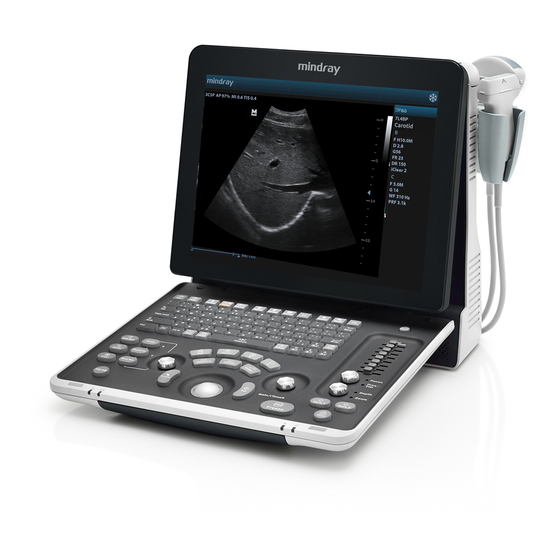
Product Specifications Overview 2.1.1 Intended Use The diagnostic ultrasound system is intended for use in clinical ultrasonic diagnosis. 2.1.2 Introduction of Each Unit Right View Product Specifications 2-1... - Page 18 Left View Rear View 2-2 Product Specifications...
- Page 19 Bottom View Name Function Probe holder Used to place the probe Display Displays the image and parameters during scanning Control Panel Refer to the 2.1.5 Control Panel. USB ports Used to connect USB devices Handle Used to carry the machine Interface panel used for inputting and outputting signals, refer to I/O Panel 2.1.3 I/O Panel.
-
Page 20: I/O Panel
2.1.3 I/O Panel Symbol Function Network port USB ports Separate video output, connecting video printer or LCD Composite video output Remote control port ECG port VGA signal output Power indicator 2.1.4 Power Supply Panel 2-4 Product Specifications... -
Page 21: Control Panel
Name Function Power inlet AC power inlet Used for equipotential connection, that balances the protective Equipotential terminal earth potentials between the system and other electrical equipment. 2.1.5 Control Panel Name Description Function Off: when system is turned off; Power button Green: when system is turned on by pressing this button. - Page 22 Name Description Function Report Press to open or close the diagnosis reports. End Exam Press to end an exam. Press to enter or exit the patient information iStation management system. User-defined key You can assign a function to the key. Biopsy Press to show or hide the biopsy guide line.
- Page 23 Name Description Function Measurement status: press to switch between the fixed and active end of the caliper; Update Multi-imaging mode: press to change the currently active window. iScape: press to start/stop image acquisition. Caliper Press to enter/ exit General Measurement Rotate: to adjust the gain Gain/ iTouch Press: to enter/ exit iTouch...
-
Page 24: Peripherals Supported
2.1.6 Peripherals Supported Item Model Graph / text printer HP OFFICEJET PRO 8100 MITSUBISHI P93W-Z Black and White Video Analog Printer SONY UP-X898MD USB port: 971-SWNOM (2-pedal) Footswitch USB port: 971-SWNOM (3-pedal) LAN Accessory LPA11 (only for CE region) If the ultrasound system cannot recognize the SONY UP-X898MD printer automatically, you may need to change the settings on the printer: push <PUSH ENTER>... -
Page 25: Monitor Specification
2.2.4 Monitor Specification Voltage Dimension 15 inch Resolution 1024×768 Adjustable angle ≤60 degree Product Specifications 2-9... -
Page 27: System Installation
System Installation Preparations for Installation NOTE: Do not install the machine in the following locations: Locations near heat generators; Locations of high humidity; Locations with flammable gases. 3.1.1 Electrical Requirements 3.1.1.1 Requirement of Regulated Power Supply Requirement of power supply is referring to 2.2.2. Due to the difference of the power supply stability of different districts, please advise the user to adopt a regulator of good quality and performance such as an on-line UPS. -
Page 28: Installation Condition
3.1.2 Installation Condition 3.1.2.1 Space Requirements Place the system with the necessary accessories at a proper position for convenient use. 1. Place the system in a room with good ventilation or having an air conditioning unit. 2. Leave at least 20cm clearance around the system to ensure effective cooling. 3. -
Page 29: Unpacking
3.2.1 Unpacking Use the scissor to clip the 2 rubber belts as follows: Use a knife to open the tapes: Take out the operation manual: Take out the probe box 1: Take out the accessory box: System Installation 3-3... - Page 30 Take out the probe box2, as follows (the box is below the accessory box): Hold the handle tightly and pull the machine with the surrounding foam: Remove the surrounding protective foam to take out the main system. 3-4 System Installation...
-
Page 31: Checking
3.2.2 Checking 1. After unpacking, check the objects in the container with the package list to see if anything is in short supply or is wrong. 2. Inspect and make sure there is no damage to the machine, no indentation, no cracks. Installation of Main Unit 3.3.1 Installing Battery... -
Page 32: Display Adjusting
3.3.3 Display Adjusting 1. Open the display as described in 3.3.2 2. Put the finger on the rim of the display and pull the display to tilt the display (90 degrees max.) 3. Tear off the screen protective film. Tilt the display Figure 3-3 Open and tilt the display Press <Fn>+ directional keys to adjust brightness and contrast. -
Page 33: Installing Probe Holder
NOTE: On the monitor, the brightness adjustment comes before contrast. After readjusting the monitor’s contrast and brightness, adjust all preset and peripheral settings. 3.3.4 Installing Probe Holder Fix the probe holder hanger into the groove of the main unit, and push downwards to confirm the installation. -
Page 34: Installing Peripherals
NOTE: Before inserting the connector into the probe port, inspect the connector pin. If the pin is bent, do not use the probe until it has been inspected / repaired / replaced. Installing Peripherals For the models of the supported peripherals, please refer to “2.1.3 Supported Peripherals”. 3.4.1 Footswitch Installation Connecting: Take 971-SWNOM as an example: insert the USB connector to the system... -
Page 35: Installing A Graph / Text Printer
Connect the Remote control line to the Remote interface in the ultrasound system IO panel. Insert the power cord to a power supply receptacle that is well grounded. Video cable Remote port Figure 3-6 Installing Analog Video Printer Digital Video Printer Connect one terminal of the data cable of the video printer to the USB port of the ultrasound system and the other terminal to the video input port of the video printer;... -
Page 36: Installing Printer Adapter
listed in section “2.1.6”. 3.4.1 Installing Printer Adapter Overview Name Function 1. Power Button Powers on the printer adapter. 2. USB port Connects the printer to the printer adapter. 3. Network port Connects the printer adapter to the Ultrasound system. Power inlet Connects the printer adapter to power by using the auxiliary output port of the Ultrasound system. - Page 37 Environment Operation Storage and Transportation Ambient 0°C-40°C -20°C-55°C temperature Relative 30%-85% (no condensation) 20%-95% (no condensation) humidity Atmospheric 700hPa-1060hPa 700hPa-1060hPa pressure System Connection Note: A maximum of 6 text/graph printers can be connected to the printer adapter at the same time.
- Page 38 2. Press the power button on the control panel of the ultrasound system, and the imaging screen is displayed. 3. Press the power button of the printer adapter, and indicator of the button turns blue. (sometimes, the printer adapter is automatically powered on together with the Ultrasound system) ...
- Page 39 Printer Adapter Preset Open the Printer Adapter page via [Setup] [Print Preset] [Printer Adapter]. Set the IP Address to 192.168.1.10 and Port number to 6666. Click [Add], and the Printer Adapter name is displayed in the Service List. Print Preset ...
-
Page 40: Installing External Dvd-R/W
3.4.2 Installing External DVD-R/W Connect the USB cable connector of the external DVD recorder to the USB port in the ultrasound system. cable Figure 3-7 Installing External DVD System Configuration 3.5.1 Power ON / OFF Connect the system power cord to the AC power, and make sure the ultrasound system and other optional devices are correctly connected. -
Page 41: System Preset
3.5.3 System Preset Press the <Setup> key to enter the [Setup] menu. Click <System Preset> to enter the screen as follows: Region System Installation 3-15... - Page 42 In the Region page, set the system language, date format, date, time and hospital related information, etc. General Click <System Preset> to enter: In this page, set the time of standby, brightness/contrast and color temperature of display,etc. Key Config 3-16 System Installation...
- Page 43 Function of keyboard keys <Print>, <Save>, F1 and the footswitch keys (left, mid, right) are user-defined. Key brightness, key volume, trackball backlight and trackball sensitivity can be adjusted. Image Preset Click [Image Preset] to enter: System Installation 3-17...
-
Page 44: Print Preset
General image parameters can be set in this page. 3.5.4 Print Preset Press <Setup> and click [Print Preset] to set video printer, graph/text printer parameters: 3-18 System Installation... - Page 45 After connecting the local printer, Click “Printer Driver”, the system will display the printer name and status (Ready) automatically which already installed printer driver successfully. Return “Printer Service” page, Select the corresponding service from the printer list and increase the service. System Installation 3-19...
-
Page 46: Network Preset
The system integrates drivers of HP printers, after HP printers are connected, drivers will be installed automatically (about 10s).If auto installation fails, icon will display on the right lower corner of the screen to warn you that manual installation is necessary. The driver installation method is as follows: Download the ppd file from HP official website (contact R&D engineer if necessary), and copy the ppd file to the storage device (USB disk as an example). - Page 47 Please select the network type according the actually status, Select “DHCP”, click [OK]. Or, select “Static”, and input the IP address, subnet mask and gateway, then click [OK]. Name Description Current Network Adapter To select the network connection mode If “DHCP” is selected, IP address will be automatically obtained DHCP from DNS server;...
- Page 48 DICOM Setting Enter the AE Title of the ultrasound system, port and PDU according to the actual situation, and then click [OK] to exit the screen. NOTE: AE Title should be the same with the SCU AE Title preset in the server (PACS/RIS/HIS).
-
Page 49: System Information
3.5.6 System Information In System Information screen, it displays the product configuration, software version, hardware & boards, and driver related information. You can check the product information here. 1. Press the <Setup> and click [System Info]. 2. Click [About Detail] to check the detailed board information. 3. -
Page 51: Hardware Principle
Hardware Principle General Structure of Hardware System Monitor Probe IO board board 4D drive board Main module board Control panel Hard disk Speaker Battery DC-DC connecting Charge/ Battery board discharge board Ultrasound signal AC-DC Power supply board Comm&control AC IN Figure 4-1 Schematic Diagram of System As a portable black-and-white ultrasonic product,the system supports two probe slots or three probe slots. -
Page 52: Main Unit
Main Unit The main unit mainly involves 3 boards: Probe board (Two probe ports are standard configuration, and three probe ports are optional) Main board IO board 4D drive board (optional) 4.2.1 Probe Board 4.2.1.1 Probe Board of Two Probe Ports A+5V LC filter A+95V... - Page 53 The probe board supplies power to corresponding Flash of saving probe ID when reading probe ID, and Flash power shuts off after getting probe ID. Support two 156-array probes (A and B), and only one probe could be chosen by relay ...
-
Page 54: Main Board
4.2.2 Main board The main board could be divided into two parts: front-end of the main board and back-end of the main board. 4.2.2.1 Front-end of main board High- CPLD control signal voltage Drive pulse circuit output High-voltage circuit control signal Control signal Probe 4D drive signal... - Page 55 PCI_PHY implements PCIE interface switching. BF FPGA can communicate with the CPU module through transferring DSP FPGA. The CPU module communicates with the probe board via BF FPGA. DSP FPGA controls the 4D drive board to output the 4D signal to the probe board. ...
-
Page 56: Io Broad
Multifunction FPGA on the back-end of the main board is to implement the REMOTE port on the IO panel. Multifunction FPGA on the back-end of the main board is to implement the ECG port on the IO panel. The CPU module implements interfaces including USB, Ethernet and VGA on the IO ... -
Page 57: Drive Board (Optional)
4.2.4 4D Drive Board (Optional) Communication & 4D Drive Board Ultrasonic si gnal Control Power supply Communication signal Voltage control Motor driving signal Power probe amplication 4D probe Hall return signal Amplifies 4D drive signal power and output signal matching the power requirement to drive the ... -
Page 58: Ultrasound System Indicator
Function: On the back-end of the main board, a special monitor IC is used to monitor signal voltages and clock battery power that are provided to the main board by the main unit box power supply module. The system temperature is detected in three positions: BF FPGA, CPU module and power ... -
Page 59: Display
4.2.7 Display Parameter High-voltage Inverter board board screen Display Brightness 3.3V 3.3V LVDS ON/OFF control IO board Brightness 3.3V control triode triode LVDS Control signal Brightness of switch Multifunction FPGA Main board Figure 4-9 Principle Diagram of Display Monitor mainly consists of the inverter board, LCD and the parameter board. Function describes as following: The inverter board produces high voltage to illuminate backlight of LCD which is adjusted ... -
Page 60: Control Panel
4.2.8 Control Panel Trackball TGC board Control panel PCBA ADC curcuit FPGA 5 status backlight Trackball indicators scan scan backlight Main driver curcuit board Main Interface Functional control Single- chip button encoder scan board +12V PWM generating Double- curcuit encoder board Buzzer driver curcuit Buzzer... -
Page 61: Power System
Power System Power supply module DC-DC Main board boar POWER 14.8V,6600mAh drive board Display Battery in place ARM control signal MUL FPGA Control signal AC in place Restart automatically Power on/off signal control Battery connecting board CPU module Power 12V、5V Temperature signal management Battery in... -
Page 62: System Power-On Control
Power Support circuit module or function Remarks description 3 +5V HDD, Control panel, Front-end of main board, Probe board 4 -5V Front-end of main board 5 5Vst CPU module 6 VDD Front-end of main board, Back-end of main board, Display 7 1V2 Back-end of main board (FPGA core voltage) 8 1V8A... - Page 63 Controlling signal Description Remarks SUS_S3_N CPU module output effectively represents that CPU system has been in the standby status, when 5VSTB which is controlled by power management FPGA is in the charging status. SUS_S4_N CPU module output effectively represents that CPU system has been in the dormancy status.
- Page 64 Pressing power button (Control panel) Receiving PWR_BTN_N effective (Power management FPGA) Is AC in place? (Ppower management FPGA) CPU_PWR_BTN_N is valid PWR_5VSTB_EN_N is valid (Power management FPGA) (Power management FPGA) SUS_S3_N and SUS_S4_N 5VSTB start-up is invalid(CPU module) (Power supply module) Indicating PWR_5VSTB_OK_N is valid 5VSTB_CPU...
-
Page 65: Function And Performance Checking Method
The chapter supplies the method to verify main function and performance of product. This is only used for reference, not preventive execution. Function checking and testing of this part shall be carried out by Mindray service engineers and the user together. -
Page 66: General Exam
General exam 5.3.1 Check Flow Check the control panel Check the monitor Check DVD Check peripherals Check ECG module Check I/O ports 5.3.2 Checking Content 5.3.2.1 Check Control Panel Procedure Standard Check the functions of all keys and knobs All keys and knobs are effective. Follow the direction: left to right, and up to down. - Page 67 5.3.2.2 Check the Display Procedure Standard Press “<Fn>+< >”, the brightness increases; and press Adjust LCD brightness “<Fn>+< >”, the brightness decreases. Adjust LCD contrast Press “<Fn>+< >”, the contrast increases; and press Display color temperature ...
-
Page 68: Function Checks
bar Code scanner: The bar code is correctly displayed on the screen. Perform code bar scanning when the ultrasound system is running normally. 5.3.2.5 Check ECG Module Procedure Standard Confirm if the ECG module is ECG trace is displayed; the heart icon is displayed ... -
Page 69: Check Flow
5.4.1 Check Flow Check each imaging mode Check the measurements Check in cine mode Check the probe application Image & video manage Record and save the exam 5.4.2 Checking Content 5.4.2.1 B Mode In B Mode scanning, the image parameter area in the right corner of the screen will display the ... - Page 70 Press <B> Enter B mode, and B image displays Gain adjustment. Rotate clockwise to increase Rotate <Gain/iTouch> Rotate anticlockwise to decrease The adjusting range is 0-100. The real-time value will be displayed in the image parameter area in the upper right corner of the screen. Depth Adjustment Rotate clockwise to increase Press <Depth/zoom>...
- Page 71 mode menu AP value is displayed in real time in the upper part of the screen. [A.power] You should perform exams according to actual situation and follow the ALARA Principle. Focus Click [Focus Number] and rotate the multifunctional knob to adjust (B mode image has max.
- Page 72 line. Then press [M] Press [M] on the control panel again to enter M Mode, then you can observe the again. tissue motion along with anatomical images of B Mode. Press <Update> To switch between the active B image and frozen B image. Tips: Adjustment of the depth, focus position or TGC to the B Mode image will lead to corresponding changes in M Mode image.
- Page 73 Menu Procedure Standard Speed Click [Speed], and rotate the multifunction knob to adjust the parameter. B mode menu-> [Speed] The lower the value the faster the refreshing. Display Format There are 4 formats available for image display: L/R, V1:1, V1:2, Full. M mode menu->...
- Page 74 5.4.2.4 PW Mode In PW Mode scanning, the image parameter area in the right corner of the screen will display the real-time parameter values as follows: Display Angle Pulse Sample Sample Image PW/CW Wall Frequency Repetition Volume Volume Angle Parameters Gain Filter...
- Page 75 Press <ESC> or <Cine> cine review. The images are still frozen but the system exits cine review. Auto Review Region Total frames Start mark Current frame Playback mark End mark 5.4.2.6 Measurement Procedure Standard In B mode Enter the application measurement mode. ...
-
Page 76: Performance Test
Performance Test 5.5.1 Test Process Resolution Detection depth Geometric Position Accuracy Blackout area test Record the exam images 5.5.2 Test Content The image used here is only for reference, stick to the image effect in the real NOTE: situation. Requirements: Display: set the contrast and brightness at the clinical application value (or the default status) Operation environment: dark room, simulating the clinical application environment. - Page 77 In condition that the transverse resolution testing targets are horizontally displayed, record the minimal distance of two targets that can be clearly recognized. Repeat the operation above for the transverse resolution testing targets at other depths. As shown in figure below. Axial resolution ...
- Page 78 When using the convex probe, keep the transverse resolution testing targets to NOTE: be displayed near the midline. When using a linear probe with steer function, do not turn on the steer function when perform the transverse resolution test. Zoom in the region where the targets located if necessary. The diameter of the target point at a certain depth is equal to the transverse resolution at the depth.
- Page 79 5.5.2.3 Geometric positioning accuracy Longitudinal geometric positioning accuracy Test Step: Do adjustments as the way in testing the maximum depth. Record the distance by 20mm each segment on the longitudinal targets line using the measurement caliper; Select the value with the greatest error (to 20mm), calculate the accuracy using the formula below The measurement caliper should be positioned at the upper edge of the target, NOTE:...
- Page 80 Transverse geometric positioning accuracy Test Step: Cover the scan surface of the phantom with water or couple gel, gently contact the probe with the scan surface Adjust the depth, making the transverse targets to be displayed in the image. Adjust the focus point to be posited beside the transverse targets (the standard is not clear) Adjust parameters like gain, TGC, making each transverse targets to be clearly displayed.
- Page 81 5.5.2.4 Blackout Area Test Step: Cover the scan surface of the phantom with water or couple gel, gently contact the probe with the scan surface Adjust the depth at a lower value, and set the focus at the nearest place to the scan surface. Decrease the value of parameters like AP, Gain until the background noise just can be seen.
-
Page 83: Software Upgrade And Maintenance
Software Upgrade and Maintenance WARNING: DO NOT directly remove a USB memory device; otherwise, the USB memory device and / or the system may be damaged. Enter the Maintenance Window NOTE: Log on the system with the identity of Service before perform system maintenance. To log on the system: When access control function has not been activated: press “Ctrl+/”... -
Page 84: System Software Installation/ Restoration
System Software Installation/ Restoration Refer to recovery guide. Installation of Optional Devices Copy the optional devices to the U disk, then insert it to the USB port of the ultrasound system; Enter [Preset], click [Maintenance] to enter [Option] menu to select the option module to be installed. - Page 85 3. Click [Install]. Select key file from the dialog box, and then click [OK]. 4. The options become Installed after the key files are installed. The corresponding function is activated after returning from preset. Note: After all modules are installed, please go to the previous interface to confirm. Trial: select the corresponding software package, and then click [Trial].
- Page 86 Note: the promotion function is only applied to the uninstalled key. If the optional key is installed, the promotion function is disabled. 2. Select the key to be promoted. 3. Click [OK] to complete the promotion. Note: it is unavailable to use promotion for multiple optional keys. For the optional key which is promoted, it can also be installed.
-
Page 87: Data Backup And Storage
Return to the system preset interface. The option status changes into Uninstalled. The uninstalling function is exclusive to internal users. The service engineers must Note: log in the system with the account of Service, and then conduct the uninstallation. Data Backup and Storage 6.4.1 Manage Settings Press <Setup>... -
Page 88: Patient Data Backup And Restore
6.4.1.1 Back up the Preset Data 1. On Manage Settings page, Click [Export] to open the [Export Data] dialogue box. 2. Select the path to save data. 3. Click [OK], a progress bar will appear and the preset data of the selected items will be exported to the specified path. -
Page 89: Software Maintenance
Software Maintenance 6.5.1 Product Configuration NOTE: [Config] is available on the Maintenance menu only if the operator logged on the system as Service. Make the product configuration file—PCF file (generated by the production line or already archived PCF file) according to specific requirements and copy to the USB disk. Connect the USB disk to the machine, click [Config] and load the file in the popped up dialogue box. - Page 90 Select the path in the Browse page to save the log, and click [OK]. When the log is exported, the system prompts “Export succeed!” click [OK] to return to the Maintenance menu. The log can be exported to the external USB storage device only, make sure the NOTE: connection between U disk and ultrasound is normal before the exporting.
-
Page 91: Display Parameter Setting
NOTE: Before uploading the log, make sure the ultrasound system has been connected to network, otherwise, the system may warn “could not connect to server” The server (smtp.163.com) is already specified by the system, the user doesn’t have to select it. Display Parameter Setting NOTE: In normal condition, when changing display assembly or main board assembly, the... -
Page 92: Hdd Partition
3. Click the upper icon in the screen (prompts “Update” if you put the cursor on it), the update step is carried out, if fails, please send to R&D center. Figure 6-1 Main Monitor Maintenance Screen 4. After update is successful, restart the machine after power off to make the data effective. HDD Partition ... - Page 93 structured report related data file and DICOM viewing software Report report template obd.bin OBD data file version.txt Version file Comment Comment file AnatomyImage Anatomical images Measurement Measurement library Doppler program and related boot configuration main file and plug-ins, remote desktop server Multilanguage string file \exe videoplay...
- Page 94 \selftest Self test log appmon_window_monitor.txt Appmon monitor log message.txt Warning message PeriLog.txt Peripheral log commentlog.txt Comment log burn_cd_msg.txt Burn log error.txt System error log \PATIENTDATA Main patient database path \Preset \Current User preset data \temporary Temporary file \PatientBack Patient back up data E drive Catalog Data...
-
Page 95: Field Replacement Unit
Field Replacement Unit This chapter lists the details of the Field Replaceable Units (FRU) of the system. Please refer to the explosive view and the FRU table below. Level 0 represent the main Assemblies of the system, and the whole system is divided into 4 Assemblies. Level X represent the main parts of Level 0 Assemblies. -
Page 96: Explosive View
Explosive View 7-2 Field Replacement Unit... -
Page 97: Assembly Explosive View
Assembly Explosive View 7.2.1 Monitor Assembly (A0) Order Number Part Name Qty. Remark 115-068553-00 Monitor Damper(FRU) With both the left one and the right one 115-063844-00 Monitor Assembly(1117Vet/1116/1156/FRU) Field Replacement Unit 7-3... -
Page 98: Operation Panel Assembly (B0)
7.2.2 Operation Panel Assembly (B0) 7-4 Field Replacement Unit... - Page 99 Order Number Part Name Qty. Remark 115-063838-00 Control Panel Assembly(1116/Vet/FRU) 115-063837-00 Control Panel Assembly(1116/Human/FRU) 115-063841-00 Dual Encodes Assembly(FRU) With trackball connecting line 115-063842-00 Single Encode Assembly(FRU) With harness 801-1150-00015-00 optical trackball unit(FRU) With trackball connecting line 801-1150-00016-00 TGC Adjustment Board(FRU) With STC connecting line 115-063875-00 Bottom Cover of Control Panel(Vet)
- Page 100 Order Number Part Name Qty. Remark B1-1 049-001743-00 silicone keyboard 7-6 Field Replacement Unit...
-
Page 101: Core Assembly (C0)
7.2.3 Core Assembly (C0) Field Replacement Unit 7-7... - Page 102 Order Number Part Name Qty. Remark 115-063879-00 Main Board Assembly(1116/FRU) The MAC address will change with the replacement of CPU module, so you may need apply the optional key for reinstalling. CPU Module with part number 115-043600-00 has been 115-043600-00 CPU Module(1112/1114 FRU) discontinued.
- Page 103 Order Number Part Name Qty. Remark remark: Software version, Serial number of unit. CE only. When applying, please 115-063852-00 HDD(Z6S/CE/FRU) remark: Software version, Serial number of unit. CE only. When applying, please 115-063853-00 HDD(Z6W/CE/FRU) remark: Software version, Serial number of unit. CE only.
- Page 104 CE only. When applying, please 115-063868-00 HDD(Z80Pro/CE/FRU) remark: Software version, Serial number of unit. CE only. When applying, please 115-063869-00 HDD(Z80Expert/CE/FRU) remark: Software version, Serial number of unit. CE only. When applying, please 115-065228-00 HDD(DP-60/CE/FRU) remark: Software version, Serial 7-10 Field Replacement Unit...
- Page 105 FDA only. When applying, please 115-066971-00 HDD(Z60/FDA/FRU) remark: Software version, Serial number of unit. FDA only. When applying, please 115-066975-00 HDD(DP-60/FDA/FRU) remark: Software version, Serial number of unit. 115-063873-00 HDD(Z60Vet/FDA/FRU) FDA only. When applying, please Field Replacement Unit 7-11...
- Page 106 Order Number Part Name Qty. Remark remark: Software version, Serial number of unit. 115-063836-00 Power Supply Module(FRU) 115-063845-00 Main Unit Fan(FRU) 115-063886-00 Battery Connection board(FRU) 115-063877-00 FrontCover Assy of MU(1117Vet/1116/1156) 043-011251-00 Handle 115-044346-00 4D Module Kit Optional 043-003940-00 Probe Holster Small 043-004917-00 large probe holster 115-011471-00...
-
Page 107: Cable Set Of Main Unit (D0)
Order Number Part Name Qty. Remark C6-1 115-051844-00 AC-DC board( FRU) C6-2 115-051845-00 DC-DC Board( FRU) C6-3 115-063846-00 Power Supply Fan(FRU) 7.2.4 Cable Set of Main Unit (D0) Order Number Part Name Qty. Remark Include D2~D9, but only one piece for 115-063885-00 Cable Set of Main Unit(FRU) each of them. - Page 108 Main board J7- DC-DC power board power signal line AC input connector - AC-DC power AC input line board J1 Control panel PCBA J2/J5 - Single Harness encoder board J1 1.Control panel PCBA J3 - Dual encoder board J1 Trackball connecting line 2.Control panel PCBA J3 - Track board assembly J1 Main board J14 - Control panel PCBA...
-
Page 109: Mobile Trolley(E0
7.2.5 UMT-170 Mobile Trolley(E0) Field Replacement Unit 7-15... - Page 110 Order Number Part Name Qty. Remark 115-037617-01 probe holder&cup bracket(FRU) 115-070488-00 Bin(FRU) 115-070487-00 UMT-170 Trolley Caster and Spanner(FRU) 7-16 Field Replacement Unit...
-
Page 111: Structure And Assembly/Disassembly
Structure and Assembly/Disassembly Structure of the Complete System Figure 8-1 Overall Exploded View Name Name Holder Null turning axis of keyboard Rear cover assembly of main unit Control panel assembly Assembly of main unit rack Bottom cover of control panel assembly Display assembly Preparations 8.2.1... -
Page 112: Engineers Required
8.2.2 Engineers Required Only technical professionals from Mindray or engineers authorized by Mindray after training can perform maintenance and check. 8.2.3 Assembly/Disassembly Required You should perform the following preparations before the disassembling of ultrasound equipment. When you stop the scanning and the image capture, you should power off the system and disconnect the system from the AC power supply, then pull out AC power cables. -
Page 113: Battery Connecting Board
NOTE: The illustration of disassemble is provided for reference only, and the concrete picture depends on the actual model. 8.3.1 Battery Connecting Board Press the clasp of the battery cover, and then rotate the battery cover down to open it. Figure 8-2 Disassembly of Battery (1) Slide battery to the right side pressing it all the time, and then remove the battery when the battery pops on the recommended distance. -
Page 114: Power Supply Module
Figure 8-5 Disassembly of Rear Cover Assembly of Main Unit (2) Remove panhead screws with washers (2 M3X6) fixed on the main unit box, and then take off the battery connecting board. Figure 8-6 Removing the Battery Connecting Board 8.3.2 Power Supply Module 1. - Page 115 Figure 8-8 Disassemble the Power Module Assembly (1) Figure 8-9 Disassemble the Power Module Assembly (2) Figure 8-10 Disassemble the Power Module Assembly (3) Remove panhead screws with washers (2 M3X6) fixed on power module assembly to take out the lower baffle and remove cables connecting the battery conversion board and the main board.
- Page 116 Remove three cables Figure 8-12 Disassemble the cables 8.3.2.1 Power module Fan After removing panhead screws with washers (5 M3X6) fixed on the power module assembly and pulling out the plug of the fan connecting cables and power input outlet connecting cables, you can take off the rear panel of power supply assembly.
- Page 117 Figure 8-15 Disassemble the Power Module Fan During the assembly, fan label must be pasted towards the surface of the machine, NOTE: and don’t confuse with fans of other products. 8.3.2.2 DC-DC Power Board Remove panhead screws with washers M3X6 (4) used to fix the DC-DC power board. Figure 8-16 Disassemble the DC-DC Power Board (1) Remove the plug of fan cable.
-
Page 118: Io Broad
8.3.2.3 AC-DC Power Board Remove panhead screws with washers M3X6 (5) used to fix the AC-DC power board (one of the screws should be removed after the fan is removed). Figure 8-19 Disassemble the AC-DC Power Board (1) After removing the connecting plug between DC-DC power board and AC-DC power board, and the connecting plug between AC-DC power board and power input, you could take out the AC-DC power board. -
Page 119: Probe Board
Remove panhead screws with washers M3X6 (4) used to secure the IO board, and then you could take out the IO board. Figure 8-22 Disassembly of the IO Board 8.3.4 Probe Board Remove rear cover assembly of the main unit (referring to 8.3.1 the 1~4 step) After removing panhead screws with washers (14 M3X6) which are installed on the rack of the main unit rear cover and cutting off cable ties fixed on the probe board, you could remove the probe board assembly backward. -
Page 120: Main Board And Cpu Module
Force point (metal handle) Cut off cable ties Figure 8-24 Disassemble the Probe Board Assembly-Three Probe Ports (Optional) NOTE: Make sure that you could pull out and push into the probe board sockets vertically when pulling out and assembling the probe board assembly on the position of the handle. - Page 121 Figure 8-26 Disassemble the Main Board Assembly (2) When removing panhead screws with washers (4 M3X6) used to fix the CPU module, you can take out the CPU module. Figure 8-27 Disassemble the CPU module NOTE: You can’t draw out the CPU module abruptly, but you would pull it out after loosening the board from the left/right side to avoid damaging the main board FPGA.
-
Page 122: Control Panel Assembly
NOTE: 1. The button cell model of the main board PCBA is Lithium 3V220mAh D20*3.2. 2. During assembly, please assemble the main board and fasten with the screws, and then install the CPU module. Turn the main board, remove the panhead screws with washers M3X6 (4 pcs), and then the 4D board (optional) can be removed. - Page 123 the control panel assembly. Figure 8-32 Disassembly of the Control Panel Assembly (3) 8.3.6.1 Encoder Board Draw out the 4 knobs upwards fixed on the encoder board on the control panel assembly. Figure 8-33 Disassemble the Encoder Board (1) After removing the connecting cable plug on the control panel and taking out countersunk head self-tapping screw PT3X10(7) used to secure the encoder board, you could remove the encoder boards.
- Page 124 Figure 8-35 Disassembly of the Trackball 8.3.6.3 TGC Board Draw out the 8 knobs upwards fixed on the TGC board on the control panel assembly. Figure 8-36 Disassembly of the TGC Board (1) After removing the connecting cable plug of TGC board and removing screws PT3X10 (4) fixed on the TGC board, you could remove the TGC board.
- Page 125 Figure 8-38 Disassembly of the Buzzer 8.3.6.5 Silicon Key Remove the encoder board, TGC board, trackball and buzzer in turn by referring to 8.3.6.1 – 8.3.6.4. Remove 18 PT3X10 self-tapping screws fixed on the control panel. Figure 8-39 Disassemble the Control Panel (1) Pull out the control panel and silicon key from the keyboard cover and then dispatch them apart.
-
Page 126: Display Assembly
8.3.7 Display Assembly Remove rear cover assembly of the main unit (referring to 8.3.1 the 1~4 step) Remove panhead screws with washers (4 M3X10) used to be secured the monitor on the rack by a screwdriver. Figure 8-41 Screws on the Display Assembly Cut off cable ties connecting the main unit on the display by diagonal cutting pliers, and then pull out the corresponding cable plugs. -
Page 127: Hard Disk
8.3.8 Hard Disk NOTE Please pay attention to the following matters during disassembling/assembling, otherwise the hard disk will be damaged: Hold the side of the hard disk, and please do not touch the board of the hard disk. Fasten the screws with the handy screw driver, and do not with the electric screw driver. -
Page 128: Speaker
Figure 8-46 Disassembly of HDD (3) NOTE: After replacing the HDD, you need to: Restore the system; Install the optional functions: Key file must be written according to MAC address of the machine, Or else, the optional function of the product will be lost. 8.3.9 Speaker 1. - Page 129 Figure 8-48 Disassembly of Speaker (2) 4. Remove 10 panhead screws with washers (M3X6) used to fix machine assembly unit to separate the machine core assembly from the front cover of the main unit. And the speaker assembly appears. Figure 8-49 Disassembly of Speaker (3) 5.
-
Page 130: Printer Adapter (Optional)
Type-2 screwdriver screws. 8.3.10.3 Engineers Required Only technical professionals from Mindray or engineers authorized by Mindray after training can perform the maintenance and the check. 8.3.10.4 Requirements You should perform the following preparations before disassembling the ultrasound device. Power off the printer adapter, and disconnect all the AC power. - Page 131 Unscrew the four M2.5 flat-headed screws and remove the rear cover of the printer adapter, as shown in the following figure: The disassembled printer adapter is shown as follows: Structure and Assembly/Disassembly 8-21...
-
Page 133: System Diagnosis And Support
System Diagnosis and Support General Status Indicator 9.1.1 Status Indicators of the Control Panel Status Icon Status definition and indicators Position indicators Power-on The indicator is not on when the system is turned off; The Control Panel status Press the key, the indicator blinks green at power on. indicator on the upper After power on, the indicator is green. -
Page 134: Status Indicator Of The Power Supply On The Io Board
Screen-saver default is and the backlight of the freezing status automatically. “mindray” showing on the control panel both monitor. restore to the previous 9-2 System Diagnosis and Support... -
Page 135: Starting Process Of The Whole System
The system is frozen. status. Ultrasound imaging hardware system is in the dormancy mode The system is on the power-off status: when Press the power switch for a connected the AC power short time, and then the system Starting the system by Power-off supply the AC indicator is is turned off by choosing from... -
Page 136: Start Process Of Complete System
9.2.1 Start Process of Complete System 9.2.1.1 Powered on by AC Basic Procedures Phenomenon The original status: no indication Finishing loading The AC status indicator on the control panel lights on, but the 3.3VSTB,Finishing loading indicators of HDD and standby are off. 5VSTB Press the power button, The Power-on status indicator flashes continuously on the control... -
Page 137: Start-Up Process Of Bios
9.2.2 Start-up Process of BIOS The start-up process of BIOS is a black-box operation, and the primary description is as following: Basic Procedures Basic phenomenon Self-test after the system power-on The LCD is blank screen in a short time. Initialization& The settings of record system & BIOS start-up display Providing the resident programmer library &... -
Page 138: Start-Up Of Doppler
9.2.4 Start-up of Doppler 9.2.4.1 Procedure of Startup Linux app initialization Initialize Related PC HDD peripherals along with PC initialization PC software initialization Initialize ultrasonic Ultrasonic HDD initialization Finish related Ultrasonic startup ,operation and software application of ultrasonic initialization software Finish initialization 9.2.4.2... - Page 139 Platform Initializing gui… initialization Ultrasonic software Peripheral Initializing ultrasound peripheral… The total initialization initialization increment is 1 Imaging Initializing ultrasound image… The total initialization increments are 2 Application Initializing ultrasound application… The total initialization increment is 1 Finishing Initialization completed… The total initialization increment is 1...
-
Page 140: Alarming And Abnormal Information
Initializing Set related information of the zoom, languages, font In increments of 1. locale… library and input Construct widget factory Configure the GUI layer Set menu items Initialize function library Construct UICenter Initializing Configure the application layer In increments of 1. gui…... -
Page 141: Turning On The System Configuration File Is Abnormal
9.3.1 Turning on the System Configuration File is Abnormal Alarming tips LOG record Suggestion Fail to open the file none Reinstall the system software. "SystemConfiguration.ini", and please check HDD data. 9.3.2 The voltage of system power is abnormal Alarming tips LOG record Suggestion ×××: System Monitor: Power supply alert! [VBAT], Current... -
Page 142: Fan Alarming
[VVV] represents the current value, and [LLL] represents the first limit of CPU temperature. Temperature The log records are the same The second alarming, XX temperature of CPU [VVV] represents the current value, and [LLL] Shut down represents the second limit of CPU temperature. Suggestion as above (XX means inversion timing,... -
Page 143: Phv Related Alarming
replace with new battery please change the battery Replace battery and confirm Battery I2C error, the malfunction module. Shutdown State Stop the illegal operation. Battery Hot Plug, Shutdown State 9.3.6 PHV Related Alarming Alarming tips LOG record Potential reason Alarm! Something is wrong with the programmed High-voltage voltage of power module, which make... -
Page 145: Care And Maintenance
Care and Maintenance 10.1 Overview These procedures in this chapter are recommended. 10.1.1 Tools, Measurement Devices and Consumables Table 10-1 Tools and Measurement Devices Tool/Measurement Devices Qty. Remarks Resin or plastic container 1 pcs Can accommodate two probes Soft brush 1 pcs About a toothbrush size Small plastic basin... -
Page 146: Care And Maintenance Items
10.1.2 Care and Maintenance Items Table 10-3 Maintenance Items and Frequency Maintain content Frequency Method Clean display Monthly Referring to 9.2.1 Clean trackball Monthly Same as the above Clean control panel Monthly Same as the above Clean probes (the head) Every time after using Same as the above Clean probe cable and the surface of... -
Page 147: Cleaning
10.2 Cleaning 10.2.1 Clean the System 10.2.1.1 Flow of Cleaning Power off and pull out the power cables Clean display Clean trackball Clean control panel Clean probe Clean holders Clean cover Figure 10-1 View of Cleaning Maintenance Before cleaning the system, be sure to turn off the power and WARNING: disconnect the power cord from the outlet. - Page 148 Trackball is one of important interface parts, which are embedded into the main unit keyboard, and part of which is exploded to be operated by users in order to implement variety of module’s control functions. Trackball is one of the most using frequency of input assemblies on the whole operation panel, and the trackball similar to a multi-directory caster can rotate in every direction drived manually, due to the feature, gas or dust can enter into module internal easily, as a result, contamination of lens would lead to the failure of the trackball.
- Page 149 Clean control panel Tools: dry soft cloth, mild soapy water Method: Use dry soft cloth to clean the surface of the system. If the system is dirty, moisten the soft cloth with mild soapy water and wipe off any stains. Use dry soft cloth to remove any moisture and allow all hard surfaces to completely air-dry.
-
Page 150: Clean The Peripherals
10.2.3 Clean the Peripherals Do the cleaning maintenance according to your actual peripheral configuration; items which are not configured can be skipped. Table 10-4 Peripherals Cleaning List Content Description First wipe off dust or stain attached to the cover of printer with Color and B/W video soft dry cloth, then clean the inside of printer. -
Page 151: System Function Check
Content Method Check the battery periodically : a) Check if battery can be charged normally when power-on: That the current capacity is 100% or capacity increases after a short time indicates that the battery can be charged normally. It takes less than 2 minutes to increase 1% capacity when the total Battery capacity is less than 90% and it takes more time when the... -
Page 152: Peripherals And Options Check
10.3.3 Peripherals and Options Check If the system is not configured with any module or peripheral, the corresponding items checking can be skipped. Table 10-7 Options, Peripherals and Accessories Check list Content Method Color and B/W video Check if the output of video printer is normal. printer Graph / text printer Check if the output of graph / text printer is normal. -
Page 153: Electrical Safety Inspection
10.3.5 Electrical Safety Inspection Only technical professionals from Mindray or engineers authorized by Mindray after training can perform electric safety inspection. Please refer to appendix A: Electrical Safety Inspection for details. Care and Maintenance 10-9... -
Page 155: Troubleshooting Of Regular Malfunctions
Troubleshooting of Regular Malfunctions 11.1 System cannot be powered on 11.1.1 Module or Board Related Descriptions Remarks Battery Li-ion 14.8V 6600mAh LI34I002A Power supply module CPU module 11.1.2 Key Points Supporting Troubleshooting Key Points Supporting Troubleshooting Remarks AC power indicator Located on control panel Power-on status indicator Backlight of the power button... -
Page 156: System Cannot Start Up Normally
The AC input is normal ,AC power indicator Power supply module fails Replace power remains off; supply module Power indicators: off AC power indicator: ON; Power supply module fails Replace power supply module Power-on status indicator: off after power button pressed Power indicators: off AC power indicator: ON;... -
Page 157: Image Fault
interface BIOS start-up graphics is normally CPU module failure Replace CPU module displayed, but it cannot be kept on Enters BIOS start-up graphics. Cannot find operating system, Find the failure cause the HDD or OS in HDD may by entering BIOS No LINUX start-up graphics be damaged. -
Page 158: Key Points Supporting Troubleshooting
4D drive board ECG module IO board 11.3.2 Key Points Supporting Troubleshooting Key Points Supporting Troubleshooting Remarks Image feature, including dark strips and noise Images appearance when contact occurs between different types of probe in different interface of probe socket. 11.3.3 Troubleshooting Fault Cause Analysis... -
Page 159: Probe Socket System Malfunction
cable shield, it can confirm by replacing the probe. The image abnormality may be caused by Replace the probe, or the swivel of the 4D probe or the 4D drive replace the 4D drive board board. It is suggested to replace the probe first, and then replace the 4D drive board. -
Page 160: Io Interface System
Main board or probe board malfunction. 11.5 IO Interface System 11.5.1 Module or Board Related Descriptions Remarks Main board CPU module IO board Speaker 11.5.2 Key Points Supporting Troubleshooting Key Points Supporting Troubleshooting Remarks Working condition of the control panel Confirm if the USB main device is functional since the control panel is connected by internal USB cable... -
Page 161: Control Panel
CPU module or IO board Confirm by replacing Network disconnected malfunction if there is no CPU module or IO abnormal network or setting failure. board. 11.6 Control Panel 11.6.1 Module or Board Related Descriptions Remarks Silicon key Control panel Dual encoder module Single encoder module Trackball module TGC module... -
Page 162: Lcd Display
Open and clean the groove Trackball failed or Dirt or obstacles jam in the abnormal trackball groove Improper setting of trackball Make a proper preset speed in system preset; Replace the trackball module Degenerated trackball performance All key of control panel are Single encoder malfunction Replace the encoder board normal,... - Page 163 Displays normally with external LCD connecting by VGA. Control panel powered on normally; Main board or Replace the main monitor board or monitor The color of some mode key turns on orange. malfunction assembly No display (blank screen) on the LCD, with backlight only;...
-
Page 164: Printer Adapter Related Troubleshooting
11.8 Printer Adapter Related Troubleshooting Failure Description Cause Analysis Measure The ultrasound system Connect the ultrasound and the printer adapter system to the printer are not properly adapter again using connected. Ethernet cables. Check whether the indicator on the printer adapter flashes The following icon is displayed at the normally after power-on, bottom right corner of the ultrasound... - Page 165 The indicator on the printer Errors occur when the adapter turns orange, and the printing printer adapter runs. Disconnect and connect the fails. power adapter, power on the printer adapter again, and verify whether the printing is normal after 1 minute.
-
Page 167: Electrical Safety Inspection
Appendix A ELECTRICAL SAFETY INSPECTION The following electrical safety tests are recommended as part of a comprehensive preventive maintenance program. They are a proven means of detecting abnormalities that, if undetected, could prove dangerous to either the patient or the operator. Additional tests may be required according to local regulations. - Page 168 ELECTRICAL SAFETY INSPECTION 1- Power Cord Plug TEST PROCEDURE The Power Plug The Power Plug Pins No broken or bent pin. No discolored pins. The Plug Body No physical damage to the plug body. No physical damage to the strain relief. No plug The Strain Relief warmth for device in use.
- Page 169 ELECTRICAL SAFETY INSPECTION Device Enclosure And Accessories TEST PROCEDURE Visual Inspection No physical damage to the enclosure and accessories. No physical damage to meters, switches, connectors, etc. No residue of fluid spillage (e.g., water, coffee, The Enclosure and Accessories chemicals, etc.).
- Page 170 ELECTRICAL SAFETY INSPECTION Device Labeling TEST PROCEDURE Check the labels provided by the manufacturer or the healthcare facility is present and legible. Main Unit Label Integrated Warning Labels Slope and High Voltage Caution Label Don’t Stress Label ...
- Page 171 ELECTRICAL SAFETY INSPECTION 4- Protective Earth Resistance VOERVIEW Protective Earth Resistance is measured using the RED test lead attached to the DUT Protective Earth terminal or Protective Earth Metal enclosure or equipotential terminal. Select the test current by pressing SOFT KEY 3 to toggle between 1AMP, 10AMP, and 25AMP. The front panel outlet power is turned off for this test.
- Page 172 ELECTRICAL SAFETY INSPECTION 4- Protective Earth Resistance metal area. Press shortcut key 3. The Protective Earth Resistance test is displayed. Press SOFT KEY 3 to select a test current (1AMP, 10AMP, or 25AMP). The selected test current is displayed in the upper right corner of the display. Press START TEST to start the test.
- Page 173 ELECTRICAL SAFETY INSPECTION Earth Leakage Test OVERVIEW Run an Earth Leakage test on the device being tested before performing any other leakage tests. Leakage current is measured the following ways: ♦ Earth Leakage Current, leakage current measured through DUT outlet Earth ♦...
- Page 174 ELECTRICAL SAFETY INSPECTION Earth Leakage Test Failure Check any short-circuits of the Y capacitor on power unit. Replace a new one if any portion defective. Check any broken of the Power Unit. Replace a new one if any portion defective. Inspect mains wiring for bad crimps, poor connections, or damage.
- Page 175 ELECTRICAL SAFETY INSPECTION Patient Leakage Current OVERVIEW Patient leakage currents are measured between a selected applied part and mains earth. All measurements may have either a true RMS or a DC-only response. TEST PROCEDURE Prepare Perform a calibration from the Mains on Applied Part menu. The following outlet conditions apply when performing this test: Normal Polarity, Earth Open, Outlet ON Normal Polarity, Outlet ON...
- Page 176 ELECTRICAL SAFETY INSPECTION Patient Leakage Current the 601PRO. Press the print data key at any time to generate a printout of the latest measurement. Figure 2 patient leakage Current Note 1, In addition to Probes ,Patient leakage current test should be perform if ECG or PCG parts used;...
- Page 177 ELECTRICAL SAFETY INSPECTION Patient Leakage Current All countries For BF ECG input and transducer 100μA Normal Condition 500μA Single Fault Condition Electrical Safety Inspection A-11...
- Page 178 ELECTRICAL SAFETY INSPECTION Mains on Applied Part Leakage OVERVIEW The Mains on Applied Part test applies a test voltage, which is 110% of the mains voltage, through a limiting resistance, to selected applied part terminals. Current measurements are then taken between the selected applied part and earth. Measurements are taken with the test voltage (110% of mains) to applied parts in the normal and reverse polarity conditions as indicated on the display.
- Page 179 ELECTRICAL SAFETY INSPECTION Mains on Applied Part Leakage Attach the applied parts to the 601PRO applied part terminals. Attach the red terminal lead to a conductive part on the DUT enclosure. Press shortcut key 7. The Mains on Applied Part test is displayed. Select the desired outlet configuration and applied part to test using the appropriate SOFT KEYS: Press START TEST (SOFT KEY 1) to begin the test.
- Page 180 ELECTRICAL SAFETY INSPECTION Mains on Applied Part Leakage could be used instead. Change another probe to confirm if the fail is caused by console. Inspect wiring for bad crimps, poor connections, or damage. If the leakage current measurement tests fail on a new unit and if situation cannot be corrected, submit a Safety Failure Report to document the system problem.
- Page 181 ELECTRICAL SAFETY INSPECTION FORM (Class I equipment) Overall assessment: □ Scheduled inspection Test item: 1, 2, 3, 9 □ Unopened repair type Test item: 1, 2, 3, 9 □ Opened repair type, not modify the power part Test item: 1, 2, 3, 4, 5, 9 including transformer or patient circuit board □...
-
Page 183: Appendix B Phantom Usage Illustration
Appendix B Phantom Usage Illustration Note: The use of Phantom is not required during Preventive Maintenance. Customer may use it as part of their Quality Assurance Program tests。 Note: Best storage and operating temperature of phantom is 10℃~35℃,do not use phantom beyond the specified temperature range, otherwise tested performance indicators may be affected. - Page 184 Targets disposal of Phantom KS107BD A1——A4 Axial resolution target group B1——B4 Lateral resolution target group Longitudinal target group Horizontal target group E1——E3 Mimic sacs with diameters of 2, 4, 6mm 4. Line Target System There are 8 groups of line targets disposed in TM material as shown in the figure. 1.A1——A4:...
- Page 185 Phantom Usage Illustration B-3...
- Page 187 P/N: 046-017671-00 (6.0)
Need help?
Do you have a question about the DP-60 and is the answer not in the manual?
Questions and answers