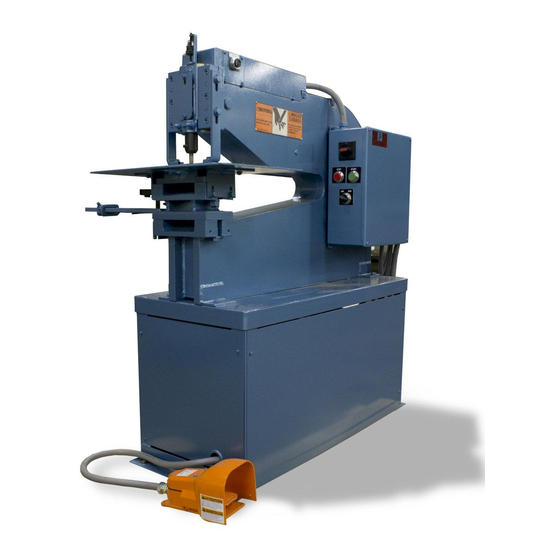
Summary of Contents for Roper Whitney 134
- Page 1 MODEL NO. 134 HYDRAULIC PRESS OPERATION, PARTS & MAINTENANCE MANUAL Model: Purchased From: Serial #: Date Received:...
- Page 2 Its purpose, aside from operations instructions, is to promote safety through the use of accepted operat- ing procedures. Read all instructions thoroughly before operating the press. Also contained in this manual is the parts list for your press. It is recommended that only Roper Whitney or factory authorized parts be used as replacements.
-
Page 3: Safety Labels
SAFETY LABELS Do not operate the hydraulic press without the proper safety labels in place. If your machine is missing the following labels please contact Roper Whitney Co. or your authorized Roper Whitney distributor to order. (This label is located on the footswitch) -
Page 4: Safety Instructions
SAFETY INSTRUCTIONS CAUTION: Before operating the 134 Hydraulic Press, read and understand this operator’s manual. Become famil- iar with the controls of the machine. FOR MAXIMUM SAFETY: * Always wear eye protection when operating this machine. * Install and use all necessary point-of-operation guards. - Page 5 1/16 and 1/32 of an inch. TOP-OF-STROKE ADJUSTMENT: After punch to die alignment is verified, the ram top-of-stroke position must be set. The stroke of the 134 press is infinitely variable between zero and one inch. To set desired stroke length, lower the punch (using the JOG setting) to the desired top-of-stroke height.
- Page 6 134 HYDRAULIC PRESS PARTS IDENTIFICATION CHART MECHANICAL - HYDRAULIC - ELECTRICAL *See page 10 for item 42, Power Unit component identification - 6 -...
-
Page 7: Front View
134 HYDRAULIC PRESS POWER UNIT COMPONENTS IDENTIFICATION ITEM #42 42C, 42D 42K, 42N 42A, 42F FRONT VIEW See pg 10, for item 42, REAR VIEW power unit component identification - 7 -... -
Page 8: Customer Connections
134 HYDRAULIC PRESS HYDRAULIC DIAGRAM ITEM #42 CUSTOMER CONNECTIONS: Manifold Ports P, A & B - #4 SAE SETTINGS: Pump Flow - 2.85 GPM Relief Valve - 1500 PSI See pg 10 for item 42, power unit component identification - 8 -... - Page 9 134 HYDRAULIC PRESS PARTS IDENTIFICATION LIST MECHANICAL - HYDRAULIC - ELECTRICAL ITEM PART NO. PART NAME QTY. 731140279 Frame 731200254 Cylinder Bracket 731240255 Cylinder Link 730560055 Connect. Link Nut 731240070 Connect. Link 731160075 Connect. Link Stud 678033119 Washer, Die Shoe Sup.
- Page 10 134 HYDRAULIC PRESS PARTS IDENTIFICATION LIST MECHANICAL - HYDRAULIC - ELECTRICAL ITEM PART NO. PART NAME QTY. Hydraulic Oil - Mobil DTE 25 or Compatible Hyd Fluid 5 gal. 669092558 Power Unit, 2 H.P. 669133107 Reservoir 669082399 Electric Motor 669021280...
- Page 11 NO. 134 HYDRAULIC PRESS PARTS IDENTIFICATION CHART - 11 -...
- Page 12 134 HYDRAULIC PRESS PARTS IDENTIFICATION LIST RAM - GAGES - ACCESSORIES ITEM PART NO. PART NAME QTY. 600356318 Knurled Nut 731030267 Threaded Rod 731180268 Rod Brace 731610133 431600019 Punch Retainer 731650275 Punch Retainer Screw Wear Plate: 731060074 731060081 3/32 731060073...
- Page 13 134 HYDRAULIC PRESS PARTS IDENTIFICATION LIST RAM - GAGES - ACCESSORIES ITEM PART NO. PART NAME QTY. Stripper Plate: 332200500 A-7 (1/2”) 332201000 B-7 (1”) Optional 332202000 C-7 (2”) Optional 332203000 D-7 (3”) Optional 332204000 E-7 (4”) Optional 731090260 Worktable...
-
Page 14: Available Tooling
AVAILABLE TOOLING LARGE PRESS TOOLING Punches and Dies for 127, 129, 130, 150, 230, 231 and 331. & 134 Power Presses Kick & Lever Presses No. 15, 811, 118, 218, 32, 34, 29, 58, 68 TYPE O ROUND PUNCHES AND DIES... - Page 15 AVAILABLE TOOLING LARGE PRESS TOOLING Punches and Dies for 127, 129, 130, 150, 230, 231 and 331. & 134 Power Presses Kick & Lever Presses No. 15, 811, 118, 218, 32, 34, 29, 58, 68 TYPE O ROUND PUNCHES AND DIES...
- Page 16 AVAILABLE TOOLING LARGE PRESS TOOLING Punches and Dies for 127, 129, 130, 150, 230, 231 and 331. & 134 Power Presses Kick & Lever Presses No. 15, 811, 118, 218, 32, 34, 29, 58, 68 TYPE O ROUND PUNCHES AND DIES...
- Page 17 AVAILABLE TOOLING LARGE PRESS TOOLING Punches and Dies for 127, 129, 130, 150, 230, 231 and 331. & 134 Power Presses Kick & Lever Presses No. 15, 811, 118, 218, 32, 34, 29, 58, 68 TYPE O ROUND PUNCHES AND DIES...
- Page 18 - 18 -...


Need help?
Do you have a question about the 134 and is the answer not in the manual?
Questions and answers