Table of Contents
Advertisement
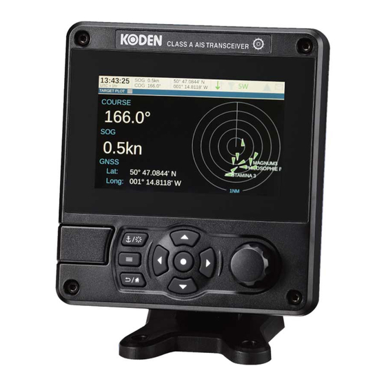
OPERATION MANUAL
CLASS A AIS / INLAND AIS TRANSCEIVER
KAT-330
This product is specifically
designed to be installed on boats
and other means of maritime
transport. If your country forms part
of the EU please contact your dealer
for advice before attempting to
install elsewhere.
KAT-330_KAT-330.OM.E 0093173302
Advertisement
Table of Contents

Related Manuals for Koden KAT-330

Summary of Contents for Koden KAT-330
- Page 1 OPERATION MANUAL CLASS A AIS / INLAND AIS TRANSCEIVER KAT-330 This product is specifically designed to be installed on boats and other means of maritime transport. If your country forms part of the EU please contact your dealer for advice before attempting to install elsewhere.
- Page 2 Thank you for purchasing this AIS Class A transceiver / Inland AIS. This product has been engineered to offer you the highest level of performance and durability and we hope that it will provide many years of reliable service. We constantly strive to achieve the highest possible quality standards, should you encounter any problems with this product, please contact your dealer who will be pleased to offer any assistance you require.
- Page 3 List of abbreviations List of abbreviations Automatic Identification System AIS SART AIS Search and Rescue Transmitter Access Point (Relating to WiFi behaviour) AtoN AIS Aid to Navigation Compact Disc European Declaration of Conformity Course Over Ground Common (electrical) Closest Point of Approach Carrier Sense Direct Current Decimal...
- Page 4 List of abbreviations External Federal Communications Committee GNSS satellite fault detection message GNSS fix accuracy and integrity message Global positioning system (GPS) fix data message Geographic position - Latitude/longitude message GLONASS Globalnaya Navigazionnaya Sputnikovaya Sistema (Russian GNSS) Electrical Ground GNSS fix data message GNSS Global Navigation Satellite System Global Positioning System...
- Page 5 List of abbreviations Liquid Crystal Display Longitude Long-range Minimum Keyboard and Display MMSI Maritime Mobile Service Identity Man Overboard Normally Closed (electrical) Navigation Nautical Miles NMEA National Marine Electronics Association Portable Document Format Parameter Group Number Presentation Interface RAIM Receiver Autonomous Integrity Monitoring Radio Equipment Directive Radio Frequency Recommended minimum specific GNSS data message...
- Page 6 List of abbreviations TDMA Time Division Multiple Access True heading and status message Threaded Neill–Concelman (a type of connector) Threads per Inch Transmit User Datagram Protocol Ultra High Frequency Co-ordinated Universal Time Dual ground/water speed message All VDL AIS messages received AIS own-ship broadcast data Very High Frequency VSWR...
-
Page 7: Table Of Contents
Table of contents Table of contents Notices ............11 Safety warnings ................11 General notices................12 Regulatory statements ..............13 Introduction ........... 17 About AIS..................17 Installation and configuration...... 19 What’s in the box? ................. 19 Preparing for installation ..............19 Installation procedures.............. - Page 8 Table of contents 4.10 Communication test ............... 60 4.11 Displaying AIS targets..............61 4.12 Micro SD card data input..............63 4.13 WiFi Feature................... 65 Inland mode........... 67 Mode SOLAS / Inland AIS.............. 67 Technical information........71 Interface circuits ................71 Output drive capability of bi-directional ports .........
- Page 9 Table of contents Applicable equipment standards............ 95 Product category................96 Physical..................97 Environmental ................98 Electrical ..................98 Display and user interface ............. 98 Internal GNSS................99 TDMA Transmitter................99 TDMA Receiver................99 8.10 DSC Receiver ................100 8.11 RF Connections ................100 8.12 WiFi....................
- Page 10 Table of contents Page 8...
- Page 11 List of figures and tables List of figures and tables Figure 1 The AIS network ..............17 Figure 2 What’s in the box? ............... 19 Figure 3 Typical AIS transceiver connection........21 Figure 4 Mounting the AIS transceiver..........23 Figure 5 Desk mounting the AIS transceiver ........
- Page 12 List of figures and tables Figure 28 Blue Sign interface connection options........ 70 Figure 29 Input port schematic............. 71 Figure 30 Data output port schematic ..........72 Figure 31 AIS Transceiver dimensions ..........74 Figure 32 GNSS Antenna ..............75 Table 8 IEC 61162 Transmission interval for periodic sentences..
-
Page 13: Notices
Notices Notices When reading this manual please pay particular attention to warnings marked with the warning triangle symbol shown on the left. These are important messages for safety, installation and usage of the AIS transceiver. 1.1 Safety warnings This equipment must be installed in accordance with the instructions provided in this manual. -
Page 14: General Notices
Notices Do not attempt to service this equipment as doing so may cause fire, electric shock or malfunction and will invalidate the warranty. If any malfunctions are detected contact your supplier or service agent. NOT ALL SHIPS CARRY AIS. The Officer of the Watch should always be aware that other ships and, in particular, leisure craft, fishing vessels and warships may not be fitted with AIS. -
Page 15: Regulatory Statements
Notices 1.2.6 Accuracy of this manual This manual is intended as a guide to the installation, setup and use of this product. If you are in any doubt about any aspect of this product, please contact your dealer. 1.3 Regulatory statements 1.3.1 Declaration of Conformity The manufacturer of this product declares that this product is in compliance... - Page 16 Notices 1.3.2 FCC Notice This equipment has been tested and found to comply with the limits for a class A digital device, pursuant to part 15 of the FCC Rules. These limits are designed to provide reasonable protection against harmful interference in a residential installation. This equipment generates, uses and can radiate radio frequency energy and, if not installed and used in accordance with the instructions, may cause harmful interference to radio communications.
- Page 17 Notices 1.3.3 Industry Canada Notice This device complies with Industry Canada licence-exempt RSS standard(s). Operation is subject to the following two conditions: 1.This device may not cause interference, and 2.This device must accept any interference, including interference that may cause undesired operation of the device. This Class A digital apparatus complies with Canadian ICES-003.
- Page 18 Notices Page 16...
-
Page 19: Introduction
Introduction Introduction 2.1 About AIS The marine Automatic Identification System (AIS) is a location and vessel information reporting system. It allows vessels equipped with AIS to automatically and dynamically share and regularly update their position, speed, course and other information such as vessel identity with similarly equipped vessels. - Page 20 Introduction Page 18...
-
Page 21: Installation And Configuration
Installation and configuration Installation and configuration 3.1 What’s in the box? Please ensure all items are present and if any of the items are missing please contact your dealer. Product mounting AIS transceiver Product template manual Quick start guide Quick operation Flyer guide Mounting bracket... -
Page 22: Installation Procedures
Installation and configuration 3.2.1 VHF Antenna Connection of a suitable VHF antenna will be required for the AIS transceiver to operate. The antenna cable should be terminated with a PL-259 (or UHF) connector. A surge arrestor should be fitted in line with VHF antenna connector. - Page 23 Installation and configuration VHF antenna GNSS antenna Surge arrestor Above decks Below decks 12V DC to 24V DC Supply Chassis/GND Optional connections NMEA 2000 Displays Ship’s sensor data (DGNSS, GYRO, Heading) (ECDIS, Radar) Figure 3 Typical AIS transceiver connection Page 21...
- Page 24 Installation and configuration 3.3.1 Step 1 - Installing the AIS transceiver Please note the following guidelines when selecting a location for your AIS transceiver: ● The AIS transceiver must be fitted in a location where it is at least 0.5m (1ft 8ins) from a compass or any magnetic device. ●...
- Page 25 Installation and configuration Panel mounted Desk mounted Overhead mounted (reverse mounting bracket) Figure 4 Mounting the AIS transceiver Refer to Figure 31. for dimensions. A drilling and cutting template is provided with the AIS transceiver. To panel mount the unit it is necessary to remove the 4 off socket cap screws recessed in front of the unit.
- Page 26 Installation and configuration Figure 5 Desk mounting the AIS transceiver Page 24...
- Page 27 Installation and configuration Figure 6 Panel mounting the AIS transceiver 3.3.2 Installing the GNSS antenna For mounting the GNSS antenna supplied with your AIS transceiver you will require a one inch 14 TPI pole mount. Contact your dealer to source a mount suitable for the installation location.
- Page 28 Installation and configuration ● The GNSS antenna should be located where it has a clear, unobstructed view of the sky overhead. ● The GNSS antenna should be mounted as high as possible, however it is not recommended to mount the antenna on the top of a high mast where the motion of the vessel will cause the antenna to move and potentially reduce the accuracy of the GNSS position.
- Page 29 Installation and configuration GNSS Antenna connection Figure 8 GNSS Antenna connection 3.3.3 Installing the VHF antenna Please note the following guidelines when selecting and locating the AIS VHF antenna: ● The VHF antenna should be located as high as possible and positioned as far from other antennas as possible.
- Page 30 Installation and configuration ● The VHF antenna cable should be kept as short as possible to minimize signal loss. High quality, low loss co-axial cable appropriate to the installation location should be used. ● The VHF antenna cable should be terminated in a PL-259 co-axial connector for connection to the AIS transceiver.
-
Page 31: Connecting The Equipment
Installation and configuration VHF antenna connection Figure 10 VHF Antenna connection 3.4 Connecting the equipment 3.4.1 Data connections The AIS transceiver is supplied with a 2m (6.5 ft) 18-way data cable and a 2m (6.5 ft) 14-way data cable for connection of the AIS transceiver to external sensors and equipment. - Page 32 Installation and configuration 3.4.3 Data input ports (14-way connector) 14-way interface connection Figure 11 Serial input port connection Page 30...
- Page 33 Installation and configuration SIGNAL WIRE COLOUR BLUE SIGN N BLACK BLUE SIGN P BROWN SILENT N BLUE SILENT P SENSOR 1 RX B ORANGE SENSOR 1 RX A PURPLE SENSOR 1 COM GREEN SENSOR 2 RX B WHITE SENSOR 2 RX A WHITE / BLACK SENSOR 2 COM GREY...
- Page 34 Installation and configuration Note: Any unused ports should be terminated by a 120 Ohm resistor across RX A and RX B signals. 3.4.4 Silent mode switch To activate the Silent mode switch, apply a voltage of between 2V and 30V to the SILENT P (Pin 7) and SILENT N (Pin 6) terminals of the 14-way connector.
- Page 35 Installation and configuration SIGNAL WIRE COLOUR LR DGNSS TX B ORANGE LR DGNSS TX A BROWN LR DGNSS RX B PURPLE 15 14 LR DGNSS RX A BLUE 11 10 LR DGNSS COM BLACK PILOT TX B PILOT TX A RED / WHITE PILOT RX B PINK...
- Page 36 Installation and configuration Note: Any unused ports should be terminated by a 120 Ohm resistor across RX A and RX B signals. COMMON signals should be grounded. All sensor ports can be configured via the Interface settings menu which can be found under the ‘Home’...
- Page 37 Installation and configuration 3.4.7 Power connection Power is connected to the AIS transceiver via the supplied 2-way power cable as shown in Figure 15. Power connection Figure 15 Power connection Wire colour Function Connect to Power supply + 12VDC to 24VDC power supply from ships emergency power source* Black...
-
Page 38: Grounding The Ais Transceiver
Installation and configuration *Connection to an emergency power source is an IMO requirement for SOLAS vessels. The power supply current ratings and recommended fusing or circuit breaker currents are as follows: ● A 12VDC supply should be able to provide a peak current of 6.0A and be fused at 10.0A. -
Page 39: Connection To An Nmea 2000 Network (Optional)
To connect your PC to an AIS transceiver, use the following You need to download and install the USB driver from the link. For Macs, you usually don't need to install a driver. https://www.koden-electronics.co.jp/en/enmarine/imo/kat-330 Follow these steps to install the driver: 1. Unzip the downloaded file. -
Page 40: Turning The Ais Transceiver On
Installation and configuration 4. Follow the on-screen instructions to complete the installation. 5. After the installation is complete, you can connect your AIS console to your PC. The AIS is automatically installed and the new COM port device is installed and appears on the screen. 6. - Page 41 Installation and configuration 16:58:29 SOG 21.1kt 50° 32.0286’ N COG 88.0° 0° 55.2715’ W UTC + 1h PASSWORD SETTINGS Enter the current password: Figure 17 Enter password screen Following configuration of the AIS transceiver the password should be changed from its default value of ‘0000’ (four zeros) to another alpha numeric code.
- Page 42 Installation and configuration Page 40...
-
Page 43: Operation
Operation Operation Please read the warning notices at the front of this manual before operating the AIS transceiver. 4.1 Display and controls Navigation status / Screen brightness Display Select Micro SD card slot behind door Options menu Back / Home Scroll wheel Function keys (push to select) -
Page 44: Button Functions
Operation 4.2 Button functions Scroll wheel. This is used to highlight information presented on the display. The scroll wheel can also be pressed to confirm data entry or select information. Navigation status / Screen brightness key. When pressed with a short press will go to the Navigation status screen. -
Page 45: Menu Navigation
Operation 4.5 Menu navigation 16:58:29 SOG 21.1kt 50° 32.0286’ N COG 88.0° 0° 55.2715’ W UTC + 1h HOME INT. GNSS Voyage Chart* Target list Target plot data settings Messages Alerts Own dynamic data System settings * The Chart feature is only enabled when this Class A AIS transceiver is operating on a non-SOLAS or Inland vessel. - Page 46 Operation HOME INBOX TARGET LIST SENT VOYAGE DATA SETTINGS COMPOSE TARGET PLOT INLAND PERSONS ON BOARD CHART* MESSAGES DISPLAY & UNIT SETTINGS ALERTS SOUND SETTINGS LANGUAGE OWN DYNAMIC DATA TIME SYSTEM SETTINGS PASSWORD FILTER AND CPA/TCPA SETTINGS USER SETTINGS INTERFACES SENSOR PORT 1 SENSOR PORT 2 SYSTEM INFORMATION...
-
Page 47: Information Displayed
Operation 4.5.2 Data entry screens Some screens allow you to enter data, such as vessel parameters. On these screens you navigate to the desired field and select the appropriate menu item. Some data entry items require a password, this is shown by means of a ‘Padlock’... - Page 48 Operation 4.6.1 Menu title Refers to the current menu displayed from Figure 20. 4.6.2 Time Time derived from GNSS satellites or AIS Base Stations. 4.6.3 Time offset Offset from UTC, set on the ‘Time’ menu. 4.6.4 Speed / Course Vessel speed and course as taken from GNSS satellite data. 4.6.5 Position Vessel position taken from GNSS source.
- Page 49 Operation Icon Description INLAND Shown when the AIS transceiver is operating in ‘Inland Waterways’ Mode Shown when the transmitter is set to 1W mode. INT GNSS Shown when the internal GNSS receiver has a valid position fix. EXT GNSS Shown when the connected external GNSS receiver has a valid position fix.
- Page 50 Operation changes to show the unacknowledged warning alert icon. Once the warning alert has been acknowledged, the acknowledged warning alert icon is displayed. If the only active alerts are caution alerts, the caution alert icon is displayed. Specific alerts can be disabled in the Alert settings menu if the relevant sensors are not installed.
- Page 51 Operation Alert Alert Identifier Alert Additional Description (Instance Information Locating Check AIS 3108 An active locating (AIS device targets SART, MOB or PLB) message has been received. The device will be displayed as the top item in the target list. Select this item to see the location of the device.
- Page 52 Operation Alert Alert Identifier Alert Additional Description (Instance Information Lost Own ship 3015 This alert occurs if the AIS position position not transceiver has no valid transmitted position information from any connected sensor. Please check the connections to the sensor. Table 6 Warnings in priority order Alert Alert...
- Page 53 Operation Alert Alert Identifier Alert Additional Description (Instance Information Sync in Check AIS for 3113 This alert indicates that the fallback UTC time transmitter is no longer synchronisation directly synchronized with the GNSS receiver. This may be because the GNSS receiver cannot receive sufficient satellites.
- Page 54 Operation Alert Alert Identifier Alert Additional Description (Instance Information Missing Not transmitting 3119 This alert occurs if the AIS transceiver has no valid Speed Over Ground information from any connected sensor. Please check the connections to the sensor. Missing Not transmitting 3119 This alert occurs if the AIS Heading...
- Page 55 Operation Alert Alert Identifier Alert Additional Description (Instance Information Doubtful Difference with 3013 This alert occurs if the heading COG exceeds difference between the limit course over ground and heading data is greater than 45° for more than 5 minutes. This alert only occurs if the vessel speed over ground is greater than 5 knots.
- Page 56 Operation 4.6.8 Messages AIS text messages and Safety Related Messages (SRMs) can be received from other AIS equipped vessels and also sent to specific vessels (addressed messages) or sent to all vessels in range (broadcast messages). Reception of an AIS text message is indicated by the presence of the message icon at the top of the screen.
- Page 57 Operation 4.6.9 Long-range messages If the AIS transceiver is connected to a long-range communication system via the long-range communications port then long-range interrogations may be received. These are requests for information from a distant base station beyond normal AIS operation range. The AIS transceiver can be configured to automatically respond to Long-range (LR) interrogations, or you can opt to respond to any interrogation manually.
-
Page 58: Configuring Vessel Information
Operation SOG vectors can also be displayed on the screen if this item is selected from the ‘Options’ menu. Some of the layers displayed on the chart can be removed to provide more clarity on the display. The ‘Chart Settings’ screen provides a way of modifying these. - Page 59 Operation ● MMSI - Vessel MMSI number, this can usually be found on the ships VHF radio license and should be the same MMSI as used for the VHF / DSC radio. ● Ship name (limited to 20 characters) ● Callsign - Vessel radio call sign (limited to 7 characters) ●...
- Page 60 Operation GNSS Antenna Ref C Stern Ref B Ref A Ref D Ref A + Ref B = Length in metres Ref C + Ref D = Beam in metres Figure 23 Vessel dimension measurement Page 58...
-
Page 61: Configuring Voyage Information
Operation 4.8 Configuring voyage information 4.8.1 Configure voyage related data The AIS transceiver must be configured with information about its voyage prior to operation. To enter the vessel identification information select the ‘Home’ > ‘Voyage Data settings’ option. The following information is required: ●... -
Page 62: Communication Test
Operation 5. Go to the ‘Home’ > ‘System settings’ > ‘System Information’ screen and select ‘Hardware status’, check that the supply voltage, forward power, and antenna VSWR are acceptable. A good VSWR is 3:1. A good Forward Power is 41dBm. The AIS transceiver is now operational and should remain powered unless authorised by the local maritime authority. -
Page 63: Displaying Ais Targets
Operation 4.11 Displaying AIS targets 4.11.1 Target list The ‘Target list’ screen is the primary screen for displaying AIS targets received. This is the first screen displayed when the unit is switched on, but can also be accessed from the ‘Target list’ option on the ‘Home’ menu. 16:58:29 SOG 21.1kt 50°... - Page 64 Operation Different symbols are shown for an AIS target depending on the type of target and its status, these are shown in Figure 25. These symbols are common to the ‘Target list’ and ‘Target plot’ displays. Base station Virtual AIS AtoN AIS Class A AIS Class B AIS SART...
-
Page 65: Micro Sd Card Data Input
Operation These CPA/TCPA figures are calculated solely on AIS data and should not be used for anti-collision purposes. Note: Setting the CPA/TCPA filter will not activate the Filters Icon. 4.11.4 Target plot The ‘Target plot’ screen shows the location of other AIS equipped vessels and shore stations relative to your own vessel. - Page 66 Operation Figure 26 Micro SD card Socket 4.12.1 Loading new charts The AIS transceiver always contains a basic low resolution world chart. More detailed resolution charts can be purchased and overlaid onto the AIS transceiver’s chart display. The AIS transceiver will read only C-MAP MAX format Micro SD cards. See your dealer for available charts for your region.
-
Page 67: Wifi Feature
Operation 4.12.2 Upgrading the unit firmware If a Micro SD card that contains valid upgrade firmware is inserted into the card socket, the unit will recognize the new firmware and will display a message asking you if you want to install it. The system will guide you to the appropriate menu screen, where the firmware update can be applied. - Page 68 Operation output a range of NMEA 0183 sentences over the selected WiFi port to any connected devices. 4.13.2 Access point mode If the AIS transceiver is configured as a WiFi access point (AP) it will create its own WiFi network, allowing other WiFi enabled devices to connect to it. Up to 5 simultaneous connections are supported.
-
Page 69: Inland Mode
Inland mode Inland mode 5.1 Mode SOLAS / Inland AIS The AIS transceiver supports both standard ‘high seas’ operation and ‘Inland AIS’ operation. Inland AIS is an extension of AIS intended for use on board vessels navigating Inland waterways. The information entered and transmitted in Inland mode is not the same as that transmitted in SOLAS mode. - Page 70 Inland mode ● The vessels ENI - this is an 8-digit number allocated to the vessel. ● The ship and convoy type as an ERI code selected from the menu provided. ● The length and beam of the ship to the nearest 10cm (greater accuracy than standard AIS configuration).
- Page 71 Inland mode The additional identification information can be entered via the ‘Voyage data settings’ menu. The voyage destination should be entered using UN terminal location codes and ERI terminal codes where possible when in Inland Mode 5.1.4 Inland alert masking Inland AIS installations do not typically include connection of external GNSS, Heading or Rate of Turn sensors to the AIS transceiver.
- Page 72 Inland mode FIELD POWER 32Vdc max. BLUE_SIGN_P OUTPUT + BLUE_SIGN_N OUTPUT - FIELD GND Remote FIELD POWER Equipment 32Vdc max. BLUE_SIGN_P CONTACT 1 BLUE_SIGN_N CONTACT 2 BLUE_SIGN BLUE_SIGN_P BLUE_SIGN_N FIELD GND 0 / 5V BLUE_SIGN_P BLUE_SIGN_N 0 / 12V BLUE_SIGN_P BLUE_SIGN_N Figure 28 Blue Sign interface connection options Page 70...
-
Page 73: Technical Information
Technical information Technical information 6.1 Interface circuits 6.1.1 Sensor data input port The sensor data input port schematic is shown in Figure 29. V ISOOUT DC to DC Converter Oscillator Rectifier V ISOIN Regulator Digital isolation Transceiver Encode Decode Encode Decode Data input port To UART... -
Page 74: Output Drive Capability Of Bi-Directional Ports
Technical information V ISOOUT DC to DC Converter Oscillator Rectifier V ISOIN Regulator Data output port From UART Digital isolation Transceiver TX_A Encode Decode TX_B Encode Decode RX_A Encode Decode RX_B ADM2587E GND 1 GND 2 Isolation Barrier RX_COM Figure 30 Data output port schematic Each bi-directional data port is isolated from the other bi- directional data ports and from the AIS transceiver’s internal power supply. -
Page 75: Dgnss Port
Technical information 6.3 DGNSS Port The DGNSS correction port is intended for connection to a beacon receiver. The port has the same physical characteristics as the bi-directional data ports as described in the preceding sections. If connection of a beacon receiver is not required this port can be re-configured as an additional bi-directional port to IEC 61162-2. -
Page 76: Ais Transceiver Overall Dimensions
Technical information 6.5 AIS Transceiver overall dimensions 75 mm 152 mm 48 mm 130 mm Figure 31 AIS Transceiver dimensions Page 74... -
Page 77: Gnss Antenna Drawing
Technical information 6.6 GNSS Antenna drawing 75 mm* 10m RG58 cable TNC (male) Figure 32 GNSS Antenna * The dimensions of the supplied antenna may vary from those shown here. 6.7 Transmission intervals The IEC 61162 sentences are in general output in response to a specific event, such as initiation of a binary message via the user interface. - Page 78 Technical information Output sentence Transmission interval Comments type Once a second Own vessel VDL reports. A ‘dummy’ VDO is generated every second. A transmission VDO is generated whenever the transceiver transmits a message. Once every thirty The cycle alert list (ALC) sentence seconds provides a list of all alerts that are not in alert state normal.
-
Page 79: Interface Sentences
Technical information 6.8 Interface sentences The IEC 61162 sentences accepted by and output by the AIS transceiver serial data ports are listed in Table 9. Data port Input sentences Output sentences Sensor 1 DTM, GBS, GGA, GLL, Sensor 2 GNS, HDT, RMC, ROT, Sensor 3 THS, VBW, VTG External... - Page 80 Technical information Alert Description TX Malfunction This alert will occur if the MMSI has not been configured. This alert can also occur if the radio hardware has failed to select the correct frequency, that the output power is too low or a transmitter shutdown has occurred.
- Page 81 Technical information Alert Description No valid SOG information This alert occurs if the AIS transceiver has no valid Speed Over Ground information from any connected sensor. Heading lost or invalid This alert occurs if the AIS transceiver has no valid heading information from any connected sensor, or if the heading is undefined.
- Page 82 Technical information Alert Description Active AIS SART An active AIS SART (AIS Search and Rescue Transmitter) message has been received. The SART will be displayed as the top item in the target list. Select this item to see the location of the SART. Internal / External GNSS This alert occurs if the difference in position mismatch...
-
Page 83: Unused Fields
Technical information 6.9 Unused fields Unused fields in the sentences from section 6.8 are listed in Table 11. All fields of other input and output sentences that are not in this table are used. Sentence Unused fields Description Channel of Interrogation Message ID 1.1 Station 1 reply slot Message ID 1.2 Station 1 reply slot Message ID 2.1 Station 2 reply slot... -
Page 84: Proprietary Sentences
Technical information Sentence Unused fields Description Number of satellites in use, 00-99 Horizontal dilution of precision Antenna altitude, m, above mean sea-level Geoidal separation, m Age of differential data Differential reference station ID Date: dd/mm/yy Magnetic variation, degrees, E/W Longitudinal water speed, knots Transverse water speed, knots Status: water speed Stern transverse water speed, knots... - Page 85 Technical information ● Heading ● Rate of Turn The sensor input ports have a priority order as shown in Table 12. Port Priority (1 = highest) Sensor 1 Sensor 2 Sensor 3 External Display Pilot Long-range Table 12 Port priority order 6.11.1 Position priority scheme Position information is taken from the highest priority source reporting DTM with WGS84 or datum override and RMC.
- Page 86 Technical information ● GBS ● GRS ● GSA ● GSV ● GFA When no position has been received on the selected port for 30 seconds, the port is deselected as a position source, and a new source selected as described above. 6.11.2 Course and Speed priority scheme COG and SOG are taken from the highest priority source reporting any one of: ●...
-
Page 87: Compatibility Mode
Technical information 6.11.4 Rate of Turn priority scheme Rate of Turn shall be taken from the highest priority sensor reporting ROT. ROT shall only be processed if they are from the currently selected Rate of Turn source. When no Rate of Turn has been received on the selected port for 30 seconds, the port shall be deselected as a Rate of Turn source, and a new source selected as described above. - Page 88 Technical information Title in NMEA database Usage NMEA 0183 (Dec.) (Hex) 060416 0EC00 ISO Transport Protocol - in, out Data 060160 0EB00 ISO Transport Protocol - in, out Connection 060928 0EE00 ISO Address Claim in, out 065240 0FED8 ISO Commanded Address 126208 1ED00 Group Function...
- Page 89 Technical information Title in NMEA database Usage NMEA 0183 (Dec.) (Hex) 129040 1F810 AIS Class B Extended VDM/VDO Position Report 129041 1F811 AIS AtoN Report VDM/VDO 129545 1FA09 GNSS RAIM 129793 1FB01 AIS UTC and Date Report VDM/VDO 129794 1FB02 AIS Class A Static and VDM/VDO Voyage Related Data...
-
Page 90: Troubleshooting
Technical information 6.15 Troubleshooting Issues Possible cause and remedy No data is being ● Check that the power supply is received by a connected connected correctly. chart plotter ● Check that the power supply is a 12VDC or 24VDC supply. ●... - Page 91 Technical information The ’Alert’ icon is ● The unit may not have a valid MMSI. illuminated or flashing Check that the AIS transceiver is correctly configured with a valid MMSI. ● The VHF antenna may be faulty. Please check the connection to the VHF antenna and that the VHF antenna is not damaged.
- Page 92 Technical information External Sensors not ● Check Compatibility Mode option in being recognised. the Interface Settings Menu. ● Check the Baud Rate set. ● Check the wiring is correct. VSWR Alert Activated or ● Ensure VHF Antenna is as far away High VSWR.
-
Page 93: Junction Box Accessory
Junction box accessory Junction box accessory 7.1 What’s in the box Please ensure all items are present and if any of the items are missing please contact your dealer. Quick Start Guide Junction Self-tapping and 14-way 18-way Unit Screws extension cable extension cable Figure 33 Junction box - What’s in the box 7.2 Installation... - Page 94 Junction box accessory a port requires no termination then that port’s jumper can be removed. ● Secure the accessory cables within the junction box with cable ties (not supplied). ● Fit the lid securely using the 8 screws provided to ensure the waterproof integrity of the unit.
-
Page 95: Connecting External Equipment
Junction box accessory 7.3 Connecting external equipment ● Figure 35. shows an example of how external equipment could be connected through the junction box accessory. AIS Transceiver 14-way data cable 18-way data cable Junction Box Displays (ECDIS, Radar) Ships sensor data (DGNSS, GYRO, Heading) Figure 35 Connecting external equipment When connecting external equipment the following procedures should be observed. -
Page 96: Technical Information
Junction box accessory ● The shield in the cable used to connect the external equipment should be connected at one end only. Refer to the manufacturer’s documentation regarding cable construction. ● The chassis connection can be made with EITHER a drain wire OR directly to the cable shield using exposed wire links on the junction box printed circuit board, depending on the cable construction. -
Page 97: Technical Specification
Technical specification Technical specification 8.1 Applicable equipment standards ITU-R M.1371-5 Technical characteristics for an automatic 02/2014 identification system using time division multiple access in the VHF maritime mobile band IEC 60945:2002 Maritime navigation and radio communication + Corr.1:2008 equipment and systems – General requirements –... -
Page 98: Product Category
Technical specification IEC 61993-2: Class A shipborne equipment of the universal 2018 automatic identification system (AIS) – Operational and performance requirements, methods of test and required test results IEC 62288 Maritime navigation and radiocommunication Ed. 2.0 equipment and systems - Presentation of navigation 2014-07 related information on shipborne navigational displays - General requirements, methods of testing... -
Page 99: Physical
Technical specification 8.3 Physical AIS Transceiver 152mm x 165mm x 111mm (WxHxD), see Figure 31. dimensions for drawing) AIS Transceiver 1.5kg weight Compass safe 0.5m (AIS Transceiver) distance Safe operating 20cm from the antenna distance Page 97... -
Page 100: Environmental
Technical specification 8.4 Environmental ° ° Operating temperature C to +55 range ° Maximum operating 90% at +40 C, non-condensing humidity Water ingress rating IPx6, IPx7 8.5 Electrical Supply voltage 12VDC to 24VDC (absolute min 10.8V, absolute max 31.2 V) Power consumption 6.2W (average) Current consumption... -
Page 101: Internal Gnss
Technical specification 8.7 Internal GNSS Receiver 72 channels GPS, GLONASS and BeiDou operating channels modes Time to first fix Typically 26 seconds Frequency L1 GPS band 1575.42MHz L1 GLONASS band 1597.1 - 1609.5MHz B1 BeiDou band 1561.098MHz Accuracy 2.5m CEP / 5.0m SEP without differential correction 2.0m CEP / 3.0m SEP with SBAS or RTCM DGNSS correction Antenna... -
Page 102: Dsc Receiver
Technical specification Modulation mode 25kHz GMSK Adjacent channel selectivity 70dB Spurious response rejection 70dB 8.10 DSC Receiver Number of receivers Frequency 156.525MHz (Channel 70) Channel bandwidth 25kHz Sensitivity -107dBm @ BER <10 Modulation mode 25kHz AFSK Adjacent channel selectivity 70dB Spurious response rejection 70dB 8.11 RF Connections... -
Page 103: Wifi
Technical specification 8.12 WiFi Maximum output power IEEE 802.11g/n +15dBm Maximum output power IEEE 802.11b +17dBm 8.13 Data interface Sensor data input ports Number of ports Standard IEC 61162-1 / -2 Baud rate 4800 baud or 38400 baud Port impedance 54K Ohms Bi-directional data ports (including pilot port) Number of ports... -
Page 104: Power And Data Connector Information
Technical specification Silent Mode port Port impedance 10K Ohms NMEA 2000 Port: Load equivalency number (LEN) 8.14 Power and data connector information Power Chogori Mating Half Chogori connector 22002525-04-RC 22002221-01 18-way data Chogori Mating Half Chogori connector 23018525-04-RC 23018221-01 14-way data Chogori Mating Half Chogori... -
Page 105: Installation Record
Installation record Installation record The following installation record should be completed and retained on board the vessel once the AIS transceiver has been installed and commissioned. 9.1 Vessel details Vessel name Flag state IMO Number MMSI Number Owner Radio call sign Type of vessel Gross registered... - Page 106 Installation record GNSS Antenna Ref C Stern Ref B Ref A Ref D Ref A + Ref B = Length in metres Ref C + Ref D = Beam in metres Figure 36 GNSS Antenna position Connected equipment type (where applicable note equipment and AIS data port in each case.
- Page 107 Installation record Maintenance Record Modification Details (enter details of modifications to the AIS record number transceiver including software updates) Installer Detail Installed by (name) Installation company name Date of installation Vessel location at installation Signature Page 105...
- Page 108 Installation record Page 106...
- Page 110 Koden Electronics Co., Ltd Tamagawa Office: 2-13-24 Tamagawa, Ota-ku, Tokyo, 146-0095 Japan Tel: +81 -3-3756-6501 Fax: +81 -3-3756-6509 Uenohara Office: 5278 Uenohara, Uenohara-shl, Yamanashl, 409-0112 Japan Tel: +81 -554-20-5860 Fax: +81 -554-20-5875 www.koden-electronics.co.jp 201-0853:7...
Need help?
Do you have a question about the KAT-330 and is the answer not in the manual?
Questions and answers