Table of Contents
Advertisement
Quick Links
MODELS:
BB ("Blue Bullet")
1302-BAS 1302-BA
Keep this operation manual near the
machine at all times. Make sure that ALL
USERS read this manual .
SHIPPING DAMAGE CLAIMS
When this equipment is shipped, title passes to the
purchaser upon receipt from the carrier. Consequently,
claims for material damaged in shipment must be made by
the purchaser against the transportation company at the
time shipment is received.
©2021 by BendPak Inc. All rights reserved.
Please read the entire contents of this manual prior to using the product.
Failure to follow the instructions and safety precautions in this manual
can result in serious injury or death. Make sure all other operators also read
this manual. Keep the manual near the product for future reference. By
proceeding with operation, you agree that you fully understand the
contents of this manual and assume full responsibility product use.
OPERATION AND SERVICE MANUAL
"America's Most Popular Tubing Bender"
P/N# 5900103 Rev. D2 - June 2021
BE SAFE
BendPak, Inc. Benders are designed and built with safety
in mind. However, your overall safety can be increased by
proper training and thoughtful operation on the part of the
operator. DO NOT operate or repair this equipment without
reading this manual and the important safety instructions
shown inside.
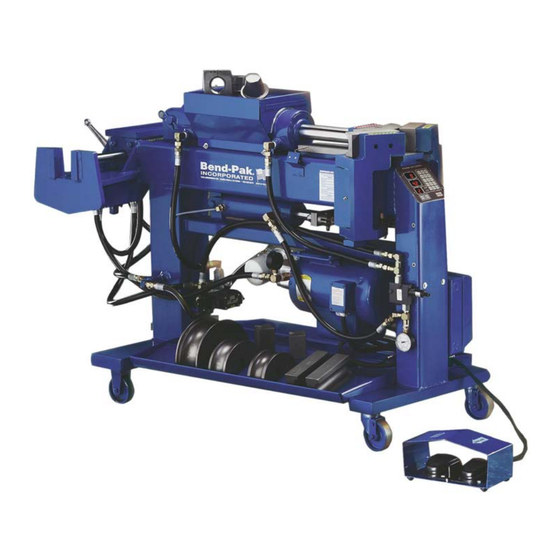
Model 1302-BA
shown.
1645 Lemonwood Dr.
Santa Paula, CA. 93060, USA
Toll Free 1-800-253-2363
Tel: 1-805-933-9970
www.bendpak.com
Advertisement
Table of Contents

Related Manuals for BendPak BB 1302-BA


Summary of Contents for BendPak BB 1302-BA
- Page 1 USERS read this manual . BE SAFE SHIPPING DAMAGE CLAIMS BendPak, Inc. Benders are designed and built with safety When this equipment is shipped, title passes to the in mind. However, your overall safety can be increased by purchaser upon receipt from the carrier. Consequently,...
-
Page 2: Table Of Contents
TABLE OF CONTENTS Identification Data / Warranty ............................. 3 Specifications ................................4 Important Safety Instructions............................5 Definition Of Terms / Model Identification ........................6 Installing The Electrical Plug ............................7 Turning Your New Bender On ............................8 Introduction Of Tooling Identification .......................... 8 Segment Identification Chart ............................. 11 Typical End Finishing Illustrations .......................... -
Page 3: Identification Data / Warranty
• Use of the product for purposes other than those described in this manual. • Modifications to the equipment without prior, written permission from BendPak Inc. • Injury or death caused by modifying, disabling, overriding, or removing safety features. •... -
Page 4: Specifications
SPECIFICATIONS DESIGN FEATURES DESIGN FEATURES MODELS 1302-BAS MODELS 1302-BA Bending Capacity ......Tubing from 1/2” OD - 3” OD Bending Capacity ......Tubing from 1/2” OD - 3” OD Maximum Capacity/Tube Thickness ..See Chart Below Maximum Capacity/Tube Thickness ..See Chart Below Maximum Bending Radius ....5” Maximum Bending Radius ....5”... -
Page 5: Important Safety Instructions
UPON DELIVERY 1. Carefully remove the crating and packing materials. 13. Check the Voltage, Phase and Amperage requirements for the Motor shown on the Motor Data 2. Inspect the Bender for any signs of concealed ship- Plate. Wiring should be performed by a Licensed, Certified Electrician only. -
Page 6: Definition Of Terms / Model Identification
INTRODUCTION Your new Bender is a “Press-Style” Bender that is capable of bending, flaring and swaging Tubing up to 3 inches in diameter. The thickness of the Tubing plays an important part in bending. (See Specifications for recommended Tubing allowances.) The front of the Bender is where all the bending is performed. -
Page 7: Installing The Electrical Plug
CONTROL FEATURES BB or BLUE-BULLET Models - A Hydraulic Control Valve is located at the front of the machine at knee height that allows the operators to manually control the machine with their leg. A Degree Plate is mounted up front that shows proper bend depths. -
Page 8: Turning Your New Bender On
OIL FILL AND INITIAL START 7. Activate the Swaging and Expanding Cylinders by pressing the directional controls located at the back UP PROCEDURES of the machine. Cycle the Cylinders to their full extent at least five times. WARNING! 8. The Hydraulic System will self-bleed any trapped air Prior to operation, you must add approximately 4.5 in the system after approximately 10 minutes of gallons (17 liters) of Anti-Foaming Hydraulic Fluid... - Page 9 Half Shoe Three-Quarter Shoe BACK SHOES - Back Shoes, which are commonly referred to as Wiper Dies come in pairs and are used together with the Radius Dies during the bending process. CAUTION! These Dies play an important part as their primary pur- pose is to form the outside radius of the bend.
- Page 10 END-FINISHING TOOLS - A variety of End Finishing REDUCING TOOLS - Reducing Tools are used for Tools are available that perform different functions. Not reducing or “shrinking” Pipe Ends to exact outside every Tool is included with your Tooling package. If you diameters.
-
Page 11: Segment Identification Chart
STANDARD SEGMENT SETS - These Segment Sets are used to make Straight Expansions on Tubing ends and are found in all standard tooling packages. HSA-112 Arbor HSA-114 Arbor WARNING! 1. Always remove excess Tooling from Swaging area before using Internal Expander. NOTE: 2. -
Page 12: Typical End Finishing Illustrations
DIGITAL CONTROL DESCRIPTION OF OPERATIONS. CONTROLS: SELCT - Selects KEYPAD or MEMORY functions. “BA” MODELS. CLEAR - Clears the SET ANGLE. ENTER - Enters the numbers displayed in SET ANGLE STOP! into memory. (Only when KEYPAD is lighted.) Before any attempt is made to operate this machine it is important that you have read and fully STEP - Advances station number display. -
Page 13: Operating The Digital Control Board (Ba Models)
4. After installing a matched Die set, position the Tubing WARNING! so that you can begin bending. 1. Either Foot Switch will act as an EMERGENCY STOP. 5. Check your “Circle-of-Swing” for allowable clearance. 2. NEVER operate the Remote Electric Foot Switches in or around water or damp areas. -
Page 14: Description Of Three-Button Control ((Bas Models)
6. Repeat these steps until all Depth-of-Bends have DESCRIPTION OF been entered. Always remember to press the CONTROLS: ENTER key prior to advancing to the next station. NEVER HOLD IN COLORED Control Buttons! - To 7. Now press the SELCT key to illuminate the MEMORY properly operate the colored Control Buttons, quickly light. -
Page 15: Operating The Manual Knee Control (Bl / Bullet Models)
To use the three-button automatic controls, follow these simple instructions. 1. Position the “Auto-Stop” pointer at the desired depth of bend. 2. Position the Tubing at the appropriate bend mark. 3. Check your “Circle-of-Swing” and prepare to begin bending. 4. Press the GREEN Control Button. 5. - Page 16 Sample screen shots of cards with specific bending instructions. Look up the make and model of the vehicle using the BENDING INSTRUCTIONS - Shows what Radius Die will Exhaust Pro Software to find the "card" or "record" be used in addition to other Tooling such as half Shoes number.
- Page 17 4. Using the program card, refer to the section marked NOTE: CENTER MARKS for the list of measurements in The weld seam on the Tubing should be directly in line inches where the different bends will be made. Each with the ZERO mark at this time. (See figure 2-A) CENTER MARK is measured from the left end of the Tubing.
- Page 18 IMPORTANT NOTE: Figure 2-B The ROTATION DIAL Degree Plate MUST NEVER be moved after bending has begun. ALWAYS be prepared to support the Tubing as it is released from the Dies to prevent it from hitting the ground. If the dial is accidentally moved during the bending process, re-position the dial so that the ZERO mark is located at the weld seam of the Tubing, or return to the previous bend and...
-
Page 19: Pattern Bending
22. Review the SYMBOLS section of the card and check Die to the original starting position. 37. You are now finished bending the pipe. Remove the for any special instructions. Figure 3-C 23. On bend number four you will notice that a REVERSE USE HALF SHOE is again called for. -
Page 20: Blank Program Card
ALWAYS USE THE NUMBERS CLOSEST TO THE CENTER OF THE ROTATION DIAL. THE OUTSIDE NUMBERS ARE FOR SPECIAL APPLICATIONS ONLY. Record the rotation degree as zero for your first PIPE ROTATION. 7. You are now ready to make your first bend. Place the first bend of the master pipe or wire flat on top of the Back Shoes. -
Page 21: Three Inch Tube Bending Procedure
Figure 2-A NOTE: Repeat these steps for the remaining bends. After all bends are completed, make the necessary end finishing and take a measurement for the overall cut off length. Be sure to make all notations on the blank program card for later reference. USING A BLOCK OF WOOD Some Bending Cards or certain bending applications require the use of a BLOCK OF WOOD. -
Page 22: Stainless Tube Bending Procedure
BENDING STAINLESS Figure 3-B TUBING In order to get good results when bending Stainless Tubing, it is necessary to increase the Back Shoe pressure by adjust- ing the Sequence Valve similar to the procedure previously described. The recommended pressures are shown below. When using large diameter or light gauge Tubing, more Back Shoe pressure is required. -
Page 23: Using The Standard Segment Expanders
USING THE STANDARD SEGMENT EXPANDERS Figure 1-A There are five standard Segment Sets included with your Bender. Each Segment Set is designed to be used with a particular size Tubing only. The appropriate sizes are shown below. Standard Segment Sets are used for making Straight Expansions. -
Page 24: Using The Ball-Joint Segment Expanders
Lift the Valve Handle up until the Arbor extends and Press the Valve Handle to form the Ball on the end the Segment Set is released. of the Tubing. Be careful not to distort the end of the Tubing. (See figure 2-A) 10. -
Page 25: Using The Manifold Flange Segment Expanders
2. Place the Tubing over the Arbor and Segment Set, but Tubing. DO NOT place the end of the Tubing past the last 3. Position the Tubing over the Arbor and Segment Set step on the Segment Set. (See figure 1-A) until the Tubing meets the shoulder. -
Page 26: Making Male Ball Expansions
MAKING STRAIGHT EXPANSIONS Follow these steps to produce Straight Expansions using 8. Separate the Collar from the Tubing. Remove Tooling the STEP Expander Dies. (See chart on page 12 for and return to the storage area. typical end finishing illustrations.) USING THE STED EXPANDER DIES OR THE B-2I2 TO MAKE MALE BALL EXPANSIONS 1. -
Page 27: Making Female Ball Expansions
4. Leave at least three inches of Tubing extended Figure 3-A beyond the inside edge of the Adapter Collar. (See figure 2-B) Figure 2-B Slowly, move the Tool forward until the desired Ball is achieved. This procedure requires careful control. (See figure 1-B) 5. -
Page 28: Making A Manifold Flange Using The Hpf-300 Tool
4. Leave at least three inches of Tubing extended Slowly, move the Tool forward until the Flare forms a beyond the inside edge of the Adapter Collar. flat surface. (See figure 2-C) (See figure 1-A) Figure 2-C Figure 1-A 3. Retract the Die by lifting up on the control handle. 5. - Page 29 5. Snug the Collar back into the Clamp Blocks by gently CAUTION! pushing back on the Collar assembly. Pay careful attention when performing the following steps. KEEP HANDS CLEAR from all 6. Slowly, while pressing the Valve Handle down, pinch points. ALWAYS remove hands from the move the shaft forward until the Tool enters the Tubing.
-
Page 30: Making A Manifold Flange Using The Cft Tool
8. Retract the Die by lifting up on the Control Handle. USING THE CFT TO MAKE A MANIFOLD FLANGE. 9. Separate the Collar from the Tubing. Remove Tooling IMPORTANT NOTE: and return to the storage area. When making a Manifold Flange, it is necessary to first install the Pipe Flange or Clamp around the Tube prior to finishing the ends. -
Page 31: Using The Doming Die To Finish Tailpipe Ends
8. Retract the Die by lifting up on the control handle. 7. Slowly, move the Tool forward until the desired finish (See figure 2-C) is achieved. (See figure 1-A) Figure 2-C Figure 1-A 9. Separate the Collar from the Tubing. Remove Tooling and return to the storage area. -
Page 32: Maintenance
5. Snug the Collar back into the Clamp Blocks by gently RECOMMENDED WEEKLY MAINTENANCE pushing back on the Collar Assembly. Clean and re-grease Guide Plate, Arbor and Swaging 6. Slowly, while pressing the Valve Handle down, Clamp Blocks. move the shaft forward until the Tool enters the Check for equal chain tension. -
Page 33: Recommended Weekly / Monthly Procedures
NOTE: The Hydraulic Oil should be changed after 1,500 9. Remove the Cannister-Type Oil Filter. (10-Micron, 200 hours of operation or yearly, whichever comes first. psi, 3/4" NPT) The Oil Filter should also be changed at this time. 10. Clean the Gasket Seat if necessary. 11. -
Page 34: Pressure Settings
attached to the Sequence Valve. (See figure 3-B) NOTE: 5. If an adjustment is required, loosen the locking nut Loose hoses and Hydraulic Components will not always that secures the adjusting screw. show a visual sign of leakage, however even small leaks can allow air into the system. - Page 35 If the return pressure needs adjusting, proceed as follows: Pump. (See figure 3-B) 1. Turn the machine on. To check and adjust the system pressure, proceed as follows: 1. Turn the machine on. 2. Place a Radius Die and set of Back Shoes in position. Tubing will not be required for this operation.
-
Page 36: Aligning The Guide Plate
LEVELING THE GUIDE PLATE WITH THE BACK GATES The Back Gates and Guide Plate have been precisely leveled at the factory and should seldom require adjustment. If however, the Guide Plate becomes un-lev- el with the Back Gates, the Bending Dies will become misaligned and cause the Tubing to wrinkle. -
Page 37: Barrel Bushing Maintenance
Figure 2-C 6. It will not be necessary to loosen the rear most bolt on the Guide Plate for this service. 7. Using a pry bar, elevate the front of the Guide Plate. (See figure 2-A) 2. Remove the barrel shaft nut located below the Left Gate Assembly. -
Page 38: Aligning The Swaging Box Cylinder
Visually check bronze bushings for excessive wear. 5. Hold the Tubing securely making sure that the Replace bushings if inside diameter is greater than HAC-300 is square within the Clamp Blocks. 2.005” or more. (See figure 3-A) 6. Advance the Tool forward until it just makes contact with the Tubing. -
Page 39: Pusher Block Maintenance
If the Pusher Block is excessively worn or out of square, Figure 1-A then replace the Pusher Block as follows. 12. Shim the Swaging Cylinder as necessary by inserting shim stock between the cylinder end block and the Swaging Box until proper alignment is achieved. (See figure 1-B) Figure 1-B 1. -
Page 40: Calibrating The Depth-Of-Bend Plate Manual Models
3. Remove the Pusher Block by sliding it to the rear end NOTE: then off of the Guide Plate. Some Tubing may experience “spring back” after the bend is made. To compensate for this, set your Depth-of-Bend 4. Carefully re-install the new Pusher Block (it should be pointer 2 degrees less than the actual position of the tight) by reversing these steps. -
Page 41: Calibrating The Digital Readout Display (Ba Models)
5. Loosen the set screw on the adjustable Trip Arm Figure 13-C located directly underneath the Depth-of-Bend Plate and adjust so that it just activates the Micro-Switch. 6. Re-tighten the set screw. 7. Retract the Radius Die and re-check. 8. If further adjustment is required, repeat steps. CALIBRATING THE DIGITAL READOUT DISPLAY / “BA”... -
Page 42: Using The Jumper Board Ba Models
4. Read the degree of bend shown in the DIE ANGLE window on the Control Board and make the following USING THE JUMPER BOARD adjustments. All “BA” models have a bypass device or “Jumper Board” NOTE: included that can be used to effectively bypass the Before making any adjustments, check to make sure that Digital Control Board for trouble shooting or diagnostic the flexible coupler or “U-Joint”... -
Page 43: Operating The Machine Manually Using The Solenoid Valve
5. With the Jumper Board in place, movement of the The manual buttons control the Top Cylinder as follows; Radius Die will be controlled by the twin Foot Switches To advance the Radius Die - Press the Right Button only. There will be no provision for Depth-of-Bend inward using an insulated Tool or non-conducting rod. -
Page 44: Checking The Micro-Switches (Automatic Models)
The following section contains instructions and WITH THE LEVER OR BUTTON PRESSED - Place one illustrations to aid in electrical repair. Most electrical of the leads from your Ohmmeter on the “common” termi- components cannot be repaired and require only removal nal of the switch and the other on the “normally open”... -
Page 45: Checking Motor Rotation
prevent damage to the Starter Switch or Motor in the 380 VoIt 50HZ Three-Phase event of an over-current situation. Single Phase Incoming Power Motor Leads machines use one (1) #B-36 heater while Three-Phase Line 1 1 and 7 machines use three (3) #B-25 heaters. Continued Line 2 2 and 8 over-current through the thermal unit will raise its... -
Page 46: Trouble Shooting Procedures
TROUBLESHOOTlNG Introduction: The troubleshooting procedures shown on the following pages contain certain systems and/or conditions, possible causes and the corrective actions required. The chart gives the easiest corrective action first, then proceeds with more difficult procedures. Be certain that the person(s) working on the machine have the ability to do the service. Only Licensed, certified Electricians should work on electrical components. - Page 47 SYMPTOM / CONDITION POSSIBLE CAUSE CORRECTIVE ACTION BAS models - The bending ram The rear limit switch is malfunctioning. Check wire connections on the rear limit continues retracting even after the rear switch. Refer to diagram on page 50. limit switch is activated. Pressure builds Check Micro-Switch with ohmmeter as up on the Sequence Valve Gauge.
- Page 48 HELPFUL DIAGNOSTIC TIPS FOR DIGITAL MODELS If you feel a control problem exists with the main circuit panel, the Jumper Board can be used to temporarily bypass the complete Control Board Assembly until repairs are made. (See page 41) If the Top Cylinder advances or retracts by itself without activating any controls and you feel the problem exists with the front display panel due to cuts or other damage, disconnect it from the main circuit panel by unplugging it from the blue wire ribbon.
-
Page 49: Bending Problems
BENDING PROBLEMS Bending complications can be usually attributed to Tubing thickness, Tubing quality or improper radius selection. The bigger the Tubing diameter, the bigger the radius and wall thickness should be. See the chart below for minimum Tubing thickness and proper radius selection. Tubing Diameter Minimum Tubing Thickness Minimum Tubing Thickness... -
Page 50: Electrical Wiring Diagrams (Models Ba & Bas)
50 Bender Operation Manual... - Page 51 Bender Operation Manual 51...
-
Page 52: Die Package For Blue Bullet
B-1 Tooling Package BENDING DIES PIPE COLLARS QTY. PART NO. TOOLING DESCRIPTION QTY. PART NO. TOOLING DESCRIPTION 5R-212 5 " Radius Die / 2-1/2" HAC-212 2-1/2" Pipe Collar 5R-214 5 " Radius Die / 2-1/4" HAC-214 2-1/4" Pipe Collar 5R-200 5 "... -
Page 53: Die Package For Blue Bullet
B2 Deluxe Tooling Package BENDING DIES PIPE COLLARS QTY. PART NO. TOOLING DESCRIPTION QTY. PART NO. TOOLING DESCRIPTION 5R-212 5 " Radius Die / 2-1/2" HAC-212 2-1/2" Pipe Collar 5R-214 5 " Radius Die / 2-1/4" HAC-214 2-1/4" Pipe Collar 5R-200 5 "... -
Page 54: Economy 202 Die Package
202 Tooling Package BENDING DIES PIPE COLLARS QTY. PART NO. TOOLING DESCRIPTION QTY. PART NO. TOOLING DESCRIPTION 5R-212 5 " Radius Die / 2-1/2" HAC-212 2-1/2" Pipe Collar 5R-214 5 " Radius Die / 2-1/4" HAC-214 2-1/4" Pipe Collar 5R-200 5 "... -
Page 55: Deluxe 302 Die Package
302 Deluxe Tooling Package BENDING DIES PIPE COLLARS QTY. PART NO. TOOLING DESCRIPTION QTY. PART NO. TOOLING DESCRIPTION 5R-212 5 " Radius Die / 2-1/2" HAC-212 2-1/2" Pipe Collar 5R-214 5 " Radius Die / 2-1/4" HAC-214 2-1/4" Pipe Collar 5R-200 5 "... -
Page 56: Parts Breakdowns
56 Bender Operation Manual... - Page 57 Bender Operation Manual 57...
- Page 58 58 Bender Operation Manual...
- Page 59 Bender Operation Manual 59...
- Page 60 60 Bender Operation Manual...
- Page 61 Bender Operation Manual 61...
- Page 62 62 Bender Operation Manual...
- Page 63 Bender Operation Manual 63...
-
Page 64: Hose Routing
64 Bender Operation Manual... - Page 65 Bender Operation Manual 65...
-
Page 66: Three-Inch Tooling Ordering Information
58 Rockwell. No cast or ductile (brittle) iron is used for any of our tooling. All BendPak benders are built with 3” bending capacity so you can order three inch dies when you need them. No other manufacturer uses our exclusive step-cut process for the die rails that actually helps contain the larger size tubing better and gives you a more uniform bend. - Page 67 58 Rockwell. No cast or ductile (brittle) iron is used for any of our tooling. All BendPak benders are built with 3” bending capacity so you can order three inch dies when you need them. No other manufacturer uses our exclusive step-cut process for the die rails that actually helps contain the larger size tubing better and gives you a more uniform bend.
-
Page 68: Notes
Notes: _____________________________________________________ _____________________________________________________ _____________________________________________________ _____________________________________________________ _____________________________________________________ _____________________________________________________ _____________________________________________________ _____________________________________________________ _____________________________________________________ _____________________________________________________ _____________________________________________________ _____________________________________________________ _____________________________________________________ _____________________________________________________ _____________________________________________________ _____________________________________________________ 68 Bender Operation Manual... - Page 69 Notes: _____________________________________________________ _____________________________________________________ _____________________________________________________ _____________________________________________________ _____________________________________________________ _____________________________________________________ _____________________________________________________ _____________________________________________________ _____________________________________________________ _____________________________________________________ _____________________________________________________ _____________________________________________________ _____________________________________________________ _____________________________________________________ _____________________________________________________ _____________________________________________________ Bender Operation Manual 69...
- Page 70 Notes: _____________________________________________________ _____________________________________________________ _____________________________________________________ _____________________________________________________ _____________________________________________________ _____________________________________________________ _____________________________________________________ _____________________________________________________ _____________________________________________________ _____________________________________________________ _____________________________________________________ _____________________________________________________ _____________________________________________________ _____________________________________________________ _____________________________________________________ _____________________________________________________ 70 Bender Operation Manual...
- Page 71 Notes: _____________________________________________________ _____________________________________________________ _____________________________________________________ _____________________________________________________ _____________________________________________________ _____________________________________________________ _____________________________________________________ _____________________________________________________ _____________________________________________________ _____________________________________________________ _____________________________________________________ _____________________________________________________ _____________________________________________________ _____________________________________________________ _____________________________________________________ _____________________________________________________ Bender Operation Manual 71...
- Page 72 For Parts Or Service Contact: BendPak Inc. / Ranger Products 1645 Lemonwood Dr. Santa Paula, CA. 93060 Tel: 1-805-933-9970 Toll Free: 1-800-253-2363 Fax: 1-805-933-9160 www.bendpak.com www.rangerproducts.com P/N: 5900103 Rev. D2 ©2021 by BendPak Inc. All rights reserved.
Need help?
Do you have a question about the BB 1302-BA and is the answer not in the manual?
Questions and answers