dji ROBOMASTER User Manual
Type c
Hide thumbs
Also See for ROBOMASTER:
- User manual (5 pages) ,
- User manual (6 pages) ,
- User manual (15 pages)
Table of Contents
Advertisement
Quick Links
Advertisement
Table of Contents

Related Manuals for dji ROBOMASTER


Summary of Contents for dji ROBOMASTER
- Page 1 Development Board Type C User Manual v1.0 2020.01...
- Page 2 Searching for Keywords Search for keywords such as “battery” and “install” to find a topic. If you are using Adobe Acrobat Reader to read this document, press Ctrl+F on Windows or Command+F on Mac to begin a search. Navigating to a Topic View a complete list of topics in the table of contents.
-
Page 3: Table Of Contents
Content Disclaimer Warning RoboMaster Development Board Type C Introduction In the Box Overview Development Board SWD Cable 2-Pin CAN Cable 4-Pin CAN Cable Mounting the Board Type C Function Description Power Supply Input Protection Circuit Customizable LED 5V Port BOOT Configuration Port... -
Page 4: Disclaimer
DJI. The final interpretation right of this disclaimer is reserved by DJI. This document and all other collateral documents are subject to change at the sole discretion of DJI. For up to date product information, visit http://www.robomaster.com and click on the product page for this product. -
Page 5: In The Box
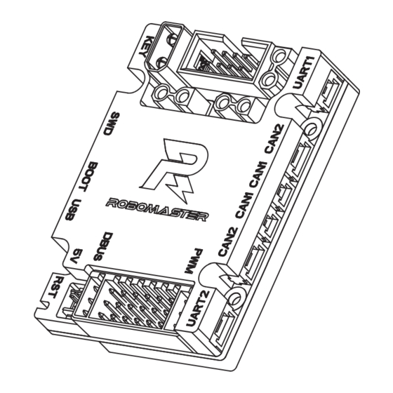
2-Pin CAN port 4-Pin UART Port 4-Pin UART port PWM Port PWM output port x 7 DBUS Port DBUS remote controller receiver port x 1 18-Pin Digital Camera FPC port for DCMI FPC Port © 2020 DJI All Rights Reserved. -
Page 6: Swd Cable
ROBOMASTER Development Board Type C User Manual XT30 Power Cable Cable length: 450 mm; A: Positive electrode (Red); B: Negative electrode (Black) SWD Cable Cable length: 100 mm; A: SWDIO (Black); B: SWCLK (Black); C: GND (Black); D: 3.3 V (Black) 2-Pin CAN Cable Cable length: 350 mm;... -
Page 7: Function Description
ROBOMASTER Development Board Type C User Manual On the Board Type C there are four mounting holes, each with an inner diameter of 2.5 mm and an outer diameter of 5 mm. The holes are used to help mount the board onto structural components. As shown below, the ESC Center Board 2 can be used as an extension port for the Board Type C. -
Page 8: Input Protection Circuit
ROBOMASTER Development Board Type C User Manual One 24 V to 5 V step-down circuit (power network VCC_5V), which is used for the onboard device power supply and as the second input of power supply. The maximum output current is 1 A. -
Page 9: 5V Port
5V Port The controllable 5V power port can be connected to the RoboMaster Red Laser Sight. The corresponding switch control IO of the port is PC8. The brightness of the RoboMaster Red Laser Sight can be adjusted via the PWM control. -
Page 10: Micro Usb Port
ROBOMASTER Development Board Type C User Manual The relationship between the STM32 boot method and BOOT configuration is shown below. Boot Mode Selection Pins Boot Mode Aliasing BOOT1 BOOT0 User Flash memory User Flash memory is selected as the boot space... -
Page 11: Swd Port
ROBOMASTER Development Board Type C User Manual SWD Port The SWD debugging port can be used for downloading and debugging programs via a dedicated emulator such as J-Link and ST-Link. 100R 0201 SWDIO 100R 0201 SWCLK VCC_3V3 0603 1.4A 53261-0471... -
Page 12: Customizable I/O Port
The two UART ports map to the UART1 4-pin external port and the UART6 3-pin external port of the STM32. The two ports can be connected to the RoboMaster Power Management Module and the baud rate can be configured. An external level conversion chip is required for the ports to communicate with a RS485 or RS232 port. -
Page 13: Can Ports
The Board Type C has two CAN ports. CAN1 port is a 2-pin port and CAN2 is a 4-pin port. The CAN ports support a maximum transmission speed of 1 Mbps and can be used to control the RoboMaster ESC or communicate with other devices. -
Page 14: Pwm Ports
ROBOMASTER Development Board Type C User Manual VCC_5V [4,8] CAN1_L [4,8] CAN1_H [4,8] CAN2_H [4,8] CAN2_L 1.25T-7-2AW 1.25T-7-4AW Horizontal Horizontal 卧式 卧式 Pin1 (CAN2) Pin1 (CAN1) CAN1 pin: CAN2 pin: CANL CANH CANH CANL PWM Ports The Board Type C has seven PWM output ports that can be used to connect 5V servo motor modules or other PWM drive modules. -
Page 15: Dbus Port
ROBOMASTER Development Board Type C User Manual Pin-C7 PWM (Pin-C1) Pin-B7 5V (Pin-B1) Pin-A7 GND (Pin-A1) DBUS Port The Board Type C has one DBUS* port that shares one connector with the PWM port. When the DBUS signal passes through the inverter circuit to connect to UART3 of STM32, the baud rate is approximately 100 kbps. -
Page 16: Digital Camera Fpc Port
ROBOMASTER Development Board Type C User Manual Digital Camera FPC Port The Board Type C has one FPC port (18-Pin) that supports DCMI and can connect 8-bit CMOS camera modules as well as support multiple data formats. VCC_3V3 PCLK_OUT R205... -
Page 17: Voltage Detection
ROBOMASTER Development Board Type C User Manual VCC_5V 10uF 510R TIM4_CH3 0402 0402 Voltage Detection The voltage detection can be used to detect the input voltage VCC_BAT. After being divided, the voltage connects to ADC (PF10) of the SMT32. D10 clamps the voltage and protects the ADC port of the STM32. -
Page 18: Magnetometer
ROBOMASTER Development Board Type C User Manual SPI1_CLK INT1_Accel INT1 SPI1_MOSI INT2 33.0R SPI1_MISO INT1_Gyro SDO1 INT3 0402 SDO2 INT4 CS1_Accel CSB1 CS1_Gyro VCC_3V3_IMU CSB2 VDDIO 100.0nF 100.0nF GNDIO PS connects GND: SPI mode PS接GND:使用SPI模式 BMI088 PS接VDD:使用IIC模式 PS connects VDD: IIC mode Heat_Power 120.0R... -
Page 19: Usage
ROBOMASTER Development Board Type C User Manual Usage The Board Type C firmware can be downloaded by SWD or DFU. Users can download and debug programs via J-Link or ST-Link (SWD mode) and also download programs to the Board Type C via USB (DFU mode). - Page 20 ROBOMASTER Development Board Type C User Manual TIM1_CH1 TIM1_CH2 PE11 TIM1_CH3 PE13 PWM Port TIM1_CH4 PE14 TIM8_CH1 TIM8_CH2 TIM8_CH3 DBUS Port UART3_RX PC11 I2C1_SCL I2C1_SDA PCLK_OUT DCMI_HREF DCMI_VSYNC DCMI_D0 Digital Camera FPC Port DCMI_D1 DCMI_D2 DCMI_D3 DCMI_D4 DCMI_D5 DCMI_D6 DCMI_D7...
- Page 21 WWW.ROBOMASTER.COM are trademarks of DJI. Copyright © 2020 DJI All Rights Reserved. Printed in China.
Need help?
Do you have a question about the ROBOMASTER and is the answer not in the manual?
Questions and answers