Advertisement
Quick Links
Thank you for purchasing a Sealey product. Manufactured to a high standard this product will, if used according to these instructions and
properly maintained, give you years of trouble free performance.
IMPORTANT: PLEASE READ THESE INSTRUCTIONS CAREFULLY. NOTE THE SAFE OPERATIONAL REQUIREMENTS, WARNINGS AND CAUTIONS.
USE THE PRODUCT CORRECTLY AND WITH CARE FOR THE PURPOSE FOR WHICH IT IS INTENDED. FAILURE TO DO SO MAY CAUSE
DAMAGE AND/OR PERSONAL INJURY AND WILL INVALIDATE THE WARRANTY. PLEASE kEEP INSTRUCTIONS SAFE FOR FUTURE USE.
1. SAFETY INSTRUCTIONS
WARNING! THIS LIFT IS ONLY SUITABLE FOR MOTORCYCLES WHICH HAVE A CENTRE STAND.
WARNING! Ensure the bike is adequately strapped onto the platform before operating.
Maintain the lift in good condition (use an authorised service agent).
Replace or repair damaged parts. Use genuine parts only. Unauthorised parts may be dangerous and will invalidate the warranty.
Use a qualified person to lubricate and maintain the lift. DO NOT use brake fluid to top up hydraulic unit.
Locate the lift in a suitable work area, keep area clean and tidy and free from unrelated materials, and ensure that there is adequate lighting.
Also ensure that the floor is level and strong enough (preferably concrete) to take the weight of the lift and the bike. DO NOT operate the lift
on tarmacadam, as the surface may be unstable.
Keep the lift clean for best and safest performance.
The maximum bike weight is 365kg. DO NOT exceed this rated capacity.
Remove ill fitting clothing. Remove ties, watches, rings and other loose jewellery, and contain long hair.
Maintain correct balance and footing, do not over reach. Ensure the floor is not slippery and wear non-slip shoes.
Ensure the bike is adequately secured to the lifting platform with appropriate straps.
Before lifting check that there are no overhead obstructions.
When platform has been raised to the working height ensure the locking bar is engaged to prevent accidental lowering.
Keep children and unauthorised persons away from the work area.
The lowering speed will vary according to the weight of the load and the amount by which the release pedal is depressed.
DO NOT use the lift for a task it is not designed to perform.
DO NOT operate the lift if damaged.
DO NOT exceed the rated capacity of the lift.
DO NOT operate the lift when you are tired or under the influence of alcohol, drugs or intoxicating medication.
DO NOT allow untrained persons to operate the lift.
DO NOT attempt to transport a load on the lift. The lift must only be used in a static position for raising and lowering loads.
DO NOT make any modifications to the lift and DO NOT adjust or tamper with the safety valve.
Before lowering the lift ensure that there are no obstructions underneath and that all persons are standing clear.
Before storing in safe area, ensure all parts are clean and free of grease and oil. Store lift in the lowest position.
2. SPECIFICATION
Specification
Capacity . . . . . . . . . . . . . . . . . . . . . . . 365kg
Minimum Height . . . . . . . . . . . . . . . . 220mm
Maximum Height . . . . . . . . . . . . . . . 760mm
3. ASSEMBLY
Unpack the lift and check contents with list below. Should there be any damaged or missing parts contact your supplier immediately.
Content
• Main Assembly
• Sliding Plate
• Lifting Pedal
• Release Pedal
WARNING! Keep your hands away from moving parts.
Numbers in brackets refer to item numbers in the parts diagram.
3.1.
Assembly
3.1.1. Attach lead plate (31) to end of platform (32) using bolts (30).
3.1.2. Fit the front wheel vice assembly (35, 47) to the front of the platform (32) using bolts (33),
washers (34) and nuts (38).
3.1.3. Insert the lift foot pedal (7) into the pump piston spindle and insert the
release foot pedal (10) into the release valve spindle (18).
3.1.4. Attach baffle plate (39) using bolts (33), washers (34) and nuts (38).
3.2.
Before first use
3.2.1. Remove the transit plug on the hydraulic pump and replace with the vented plug (fig. 1.A) provided.
3.2.2. Leave the pump for one hour, to allow the oil to settle, before purging the system.
Note: Failure to allow sufficient time for the oil to settle could result in air remaining in the oil. In this event, the pump will not purge
completely first time and a second purge will be required.
3.2.3. Purge the hydraulic circuit to eliminate any air in the system, by fully pressing the release valve pedal (10) and pumping the lift pedal
(7) 15 to 20 times.
3.2.4. Test the lift, unladen, by raising it to full height and then lowering it. Depress release valve pedal (10) slowly to control the rate of
descent.
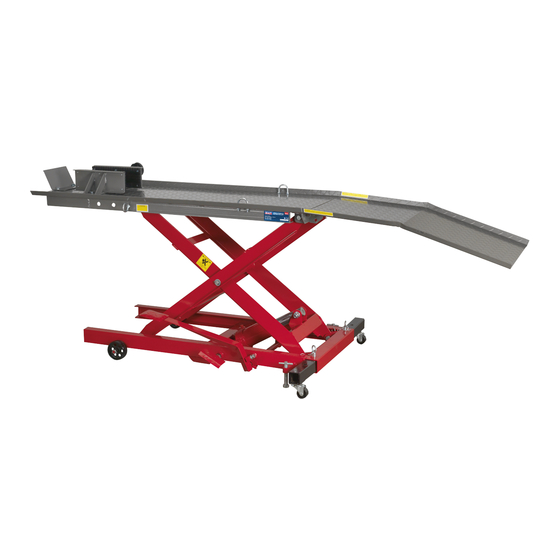
INSTRuCTIoNS FoR:
365kG HYDRAULIC MOTORCYCLE LIFT
MoDEL No:
Width. . . . . . . . . . . . . . . . . . . . . . . . 480mm
Length . . . . . . . . . . . . . . . . . . . . . . 2215mm
Max. Load Length . . . . . . . . . . . . . 1350mm
• Leading Plate
• Vice
• Bolts, Washers, Nuts, Cotter Pins
Original Language Version
MC365
fig. 1
MC365
Issue: 3 - 01/06/11
Advertisement

Related Manuals for Sealey MC365


Summary of Contents for Sealey MC365
- Page 1 MC365 MoDEL No: Thank you for purchasing a Sealey product. Manufactured to a high standard this product will, if used according to these instructions and properly maintained, give you years of trouble free performance. IMPORTANT: PLEASE READ THESE INSTRUCTIONS CAREFULLY. NOTE THE SAFE OPERATIONAL REQUIREMENTS, WARNINGS AND CAUTIONS.
- Page 2 2) Remove vented plug (fig.1.A). Correct oil level is up to plug aperture - add hydraulic oil as necessary. WARNING! Only a good quality hydraulic oil, such as SEALEY HYDRAULIC OIL, must be used. DO NOT use brake fluid. ...
- Page 3 SERIAL NuMBER: CoMPANY CoNDuCTING TEST: This test was commissioned by Jack Sealey Limited, Kempson Way, Suffolk Business Park, Bury St. Edmunds, Suffolk, 1P32 7AR and was undertaken by Catic, the manufacturer of the product in China and the holder of the construction file.