Advertisement
Quick Links
Q ui c k Sta r t G u id e
2-Port Media Converter
ICC-MMC-WW
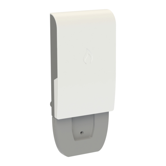
1. Unpack and Check Contents
ICC-MMC-WW Media Converter
Grounding screw
2. Mount the Media Converter
a. Mounting on a Pole
1
2
1
Place the unit against the pole (diameter 20-200 mm).
2
Use up to 12 mm (1/2 in) strapping to secure the unit to the
pole.
b. Mounting on a Wall
2
1
1
In the required location, mark and drill three holes in the wall
for M4 wall anchors (not included).
Note:
For a wood wall, drilling holes and using wall anchors
is not required.
2
Mount the unit on the wall and secure it in place using three
M4 x20 tapping screws (not included).
www.ignitenet.com
3. Ground the Media Converter
1
1
Ensure the structure on which the unit is to be mounted is
properly grounded and in compliance with ETSI ETS 300 253.
Verify that there is a good electrical connection to a
grounding point (no paint or isolating surface treatment).
2
Use the included screw to attach a grounding wire (not
included) to the grounding point inside the unit, and then to
ground.
Caution:
The earth connection must not be removed
unless all supply connections have been disconnected.
4. Connect Power
The media converter can be powered by a 24 to 48 VDC passive PoE
injector or by connecting an external 24 to 48 VDC power source to
its DC terminal block.
a. PoE Power
1
Connect Category 5e or better cable to the PoE Out/In RJ-45
port.
Connecting Ethernet cable from an optional passive PoE
injector can power on the unit. (Does not require a DC power
connection.)
Note:
When powered by PoE, the DC terminal block
provides a DC power output. When powered by a DC power
input, the RJ-45 port functions as a PoE PSE (power source)
port.
In PoE PSE mode, the RJ-45 port pin definitions can be
modified by a switch on the panel:
◆
IgniteNet: + (pins 1/2 & 4/5), - (pins 3/6 & 7/8)
◆
Other: + (pins 4/5), - (pins 7/8)
In PoE input mode, the switch position has no function.
– 1 –
1
Advertisement

Related Manuals for IgniteNet ICC-MMC-WW

Summary of Contents for IgniteNet ICC-MMC-WW
- Page 1 M4 x20 tapping screws (not included). ◆ IgniteNet: + (pins 1/2 & 4/5), - (pins 3/6 & 7/8) ◆ Other: + (pins 4/5), - (pins 7/8) In PoE input mode, the switch position has no function.
- Page 2 Quick Start Guide b. DC Power 7. (Optional) Add Cable Strain-Relief Attachment Warning: Before wiring the DC block or connecting power to the device, ensure that power to the feed lines is turned off at the supply circuit breaker or disconnected from the power bus.
- Page 3 The Declaration of Conformity (DoC) can be obtained from frequency energy and, if not installed and used in accordance with the www.ignitenet.com/support. instruction manual, may cause harmful interference to radio communications. Operation of this equipment in a residential area is...
- Page 4 Quick Start Guide Hardware Specifications Chassis Size (WxDxH) 119 x 182.8 x 30 mm (4.69 x 7.2 x 1.18 in) Weight 425 g (0.94 lb) Temperature Operating: -20° C to 65° C (-4° F to 149° F) Storage: -40° C to 70° C (-40° F to 158° F) Humidity Operating: 5% to 90% (non-condensing) ◆...
Need help?
Do you have a question about the ICC-MMC-WW and is the answer not in the manual?
Questions and answers