FlowLine DataLoop LI25 Series Instruction Manual
Hide thumbs
Also See for DataLoop LI25 Series:
- Quick start manual (9 pages) ,
- Instruction manual (40 pages)

Related Manuals for FlowLine DataLoop LI25 Series


Summary of Contents for FlowLine DataLoop LI25 Series
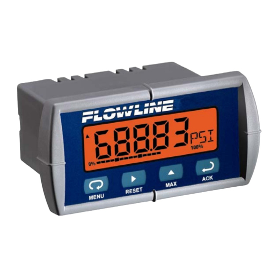
- Page 1 ™ DataLoop Loop-Powered Meters CALL TOLL FREE 877-742-2878 FOR SALES AND SUPPORT. CLICK HERE TO RETURN TO WEBSITE LI25 Series Instruction Manual Loop- Powered Backlight Standard! LIM60000FL2 Rev B MN301034 rev D...
-
Page 2: Ordering Information
REGISTERED TRADEMARKS NORYL® and LEXAN® are registered trademarks of General Electric Company. All other trademarks mentioned in this document are the property of their respective owners. © 2013 Flowline, Inc. All rights reserved. Visit our Web Site http://www.flowline.com MN301034 rev D... -
Page 3: Table Of Contents
DataLoop™ LI25 Level Controller Instruction Manual TABLE OF CONTENTS INTRODUCTION ....................2 ORDERING INFORMATION ................. 2 SPECIFICATIONS ....................5 General ......................5 Input ......................... 6 LI25 SERIES COMPLIANCE INFORMATION ............7 Ratings and Approvals ..................7 SAFETY INFORMATION ..................7 INSTALLATION ..................... - Page 4 DataLoop™ LI25 Level Controller Instruction Manual Information Menu (InFO) ................29 Operation ......................30 Front Panel Buttons Operation ..............30 Maximum & Minimum (MAX & MIN) ............31 MOUNTING DIMENSIONS ................. 32 Reset Meter to Factory Defaults ..............33 Factory Defaults & User Settings .............. 34 TROUBLESHOOTING ..................
-
Page 5: Specifications
DataLoop™ LI25 Level Controller Instruction Manual SPECIFICATIONS Except where noted all specifications apply to operation at +25°C. General Five digits 0.60" (15.2 mm) high, 7-segment, DISPLAY automatic lead zero blanking. -99999 99999 Four characters 0.25" (6.4 mm) high, 14 segment. (Engineering Units) Bar graph 20-segment, 0% to 100% indication. -
Page 6: Input
DataLoop™ LI25 Level Controller Instruction Manual Screw terminal connectors: 4.5 lb-in (0.5 Nm) TIGHTENING Mounting screws: 8.0 lb-in max. (0.9 Nm) TORQUE 4.68" x 2.45" x 3.79" (119 mm x 62 mm x 96 mm) OVERALL (W x H x D) DIMENSIONS 5.7 oz (162 g) WEIGHT... -
Page 7: Li25 Series Compliance Information
DataLoop™ LI25 Level Controller Instruction Manual LI25 SERIES COMPLIANCE INFORMATION Ratings and Approvals Class I, Div 1, 2, Groups ABCD Class II, Div 1, Groups EFG Class II, Div 2, Groups FG Class III, Div 1, 2 Class 1, Zone 0, Group IIC Class I, Div 1, 2, Groups ABCD Class II, Div 1, Groups EFG Class II, Div 2, Groups FG... -
Page 8: Installation
DataLoop™ LI25 Level Controller Instruction Manual INSTALLATION There is no need to remove the meter from its case to complete the installation, wiring, and setup of the meter. Unpacking Remove the meter from box. Inspect the packaging and contents for damage. Report damages, if any, to the carrier. -
Page 9: Figure 1. Panel Cutout And Mounting
DataLoop™ LI25 Level Controller Instruction Manual Gasket Removable Connector Panel 3.622" (92mm) Square Corners to 0.060" (1.5mm) Max Radius 1.772" Panel Cutout (45mm) to DIN 43700 Tolerances: A: +0.032 (+0.8mm) -0.000 (-0.0mm) Mounting Mounting B: +0.024 (+0.6mm) Bracket Screw -0.000 (-0.0mm) Figure 1. -
Page 10: Connections
DataLoop™ LI25 Level Controller Instruction Manual CONNECTIONS Signal connections are made to a four-terminal removable connector. This section is only intended for the LI25-1001. LI25-2001 installation must be performed in accordance with Control Drawing QS301034-1 in order to meet agency approval ratings. Observe all safety regulations. -
Page 11: 4-20 Ma Input Connections
DataLoop™ LI25 Level Controller Instruction Manual 4-20 MA INPUT CONNECTIONS Input connections are made to a four-terminal connector labeled S+|S-|B+|B-. The loop-powered backlight is an optional configuration and requires a total maximum voltage drop of 5.7 V. The backlight is recommended for dim lighting conditions and is enabled when wired as shown in Figure 3. -
Page 12: Setup And Programming
DataLoop™ LI25 Level Controller Instruction Manual SETUP AND PROGRAMMING • There is no need to recalibrate the meter for milliamps when first received from the factory. • The meter is factory calibrated for milliamps prior to shipment. The calibration equipment is certified to NIST standards. -
Page 13: Front Panel Buttons & Status Indicators
DataLoop™ LI25 Level Controller Instruction Manual FRONT PANEL BUTTONS & STATUS INDICATORS Button Description Symbol Status Symbol Bar graph Menu minimum Bar graph Right arrow/Reset 100% maximum Increasing trend Up arrow/Max Decreasing trend Enter/Ack Press the Menu button to enter or exit the Programming Mode at any time. ... -
Page 14: Main Menu Display Functions & Messages
DataLoop™ LI25 Level Controller Instruction Manual MAIN MENU DISPLAY FUNCTIONS & MESSAGES The meter displays various functions and messages during setup, programming, and operation. The following table shows the main menu functions and messages in the order they appear in the menu. Display Parameter Action/Setting... -
Page 15: Main Menu
DataLoop™ LI25 Level Controller Instruction Manual Main Menu The main menu consists of the most commonly used functions: Setup, Program, and Password. Press Menu button to enter Programming Mode then press Up arrow button to scroll main menu. Press Menu, at any time, to exit and return to Run Mode. -
Page 16: Setting Up The Meter (Setup)
DataLoop™ LI25 Level Controller Instruction Manual The decimal point is set using the Right or Up arrow button in the Setup-decimal point menu. Setting Up the Meter (SETuP) The Setup menu is used to select: Decimal point position Engineering units display Press the Enter/Ack button to access any menu or press Up arrow button to scroll through choices. -
Page 17: Setting The Units Display (Units)
DataLoop™ LI25 Level Controller Instruction Manual Pressing the Right or Up arrow moves the decimal point one place to the right until no decimal point is displayed, then it moves to the left most position. Setting the Units Display (units) The meter can be set to display a combination of three alphanumeric characters for engineering units or for identification (eg. - Page 18 DataLoop™ LI25 Level Controller Instruction Manual The upper right alphanumeric character may also be selected. This character includes degree symbols and a degrees symbol and “x10” symbol (eg. °C, °F, x103, x106, x109). Press the Enter/Ack button, at any time, to accept the programmed unit or tag. Press the Menu button to exit without saving changes.
-
Page 19: Programming The Meter (Prog)
DataLoop™ LI25 Level Controller Instruction Manual prOG Programming the Meter It is very important to read the following information, before proceeding to program the meter: • There is no need to recalibrate the meter for milliamps when first received from the factory. •... -
Page 20: Scaling The Meter (Scale)
DataLoop™ LI25 Level Controller Instruction Manual sCAlE Scaling the Meter The 4-20 mA input can be scaled to display the process in engineering units. A signal source is not needed to scale the meter; simply program the inputs and corresponding display values. Press Ack to Accept Setting Press Up to Set Digit Value Press Right to Select Next Digit... -
Page 21: Calibrating The Meter (Cal)
DataLoop™ LI25 Level Controller Instruction Manual Calibrating the Meter (Cal) To scale the meter without a signal source refer to Scaling the Meter ), page 21. sCAlE The meter can be calibrated to display the process in engineering units by applying the appropriate input signal and following the calibration procedure. -
Page 22: Setting Up The Bargraph (Graph)
DataLoop™ LI25 Level Controller Instruction Manual GrApH Setting Up the Bargraph The meter can be set to display a bargraph proportional to the percentage process reading within a user-defined span. The span is determined by values entered for 0% and 100%. If the 0% and 100% values are the same as the values that were entered for display 1 and display 2, respectively, from the scale or calibrate steps, then it is not necessary to modify them. -
Page 23: Setting Up The Password (Pass)
DataLoop™ LI25 Level Controller Instruction Manual PASS Setting Up the Password The Password menu is used to program a five-digit password to prevent unauthorized changes to the programmed parameter settings. Locking the Meter Enter the Password menu and program a five-digit password. For instructions on how to program numeric values see Setting Numeric Values, page 16. -
Page 24: Unlocking The Meter
DataLoop™ LI25 Level Controller Instruction Manual Unlocking the Meter If the meter is password protected, the correct password must be entered in order to make changes to the parameter settings. Entering the correct five-digit number sets the password to 00000, disabling the protection. -
Page 25: Advanced Features Menu
DataLoop™ LI25 Level Controller Instruction Manual Advanced Features Menu To simplify the setup process, functions not needed for most applications are located in the Advanced features menu. Press and hold the Menu button for five seconds to access the Advanced features of the meter MN301034 rev D... -
Page 26: Advanced Features Menu & Display Message
DataLoop™ LI25 Level Controller Instruction Manual Advanced Features Menu & Display Messages The following table shows the Advanced features menu functions and messages in the order they appear in the menu. Display Parameter Action/Setting Funct Enter Function menu Function LnEAr Set linear scaling Linear Set square root extraction... -
Page 27: Math Functions (Lnear, Squar, Proge, Cutof)
DataLoop™ LI25 Level Controller Instruction Manual lnEAr SquAr ProGE Cutof Math Functions The LI25 SERIES provides a number of math functions to condition outputs from linear and non-linear transmitters. lnEAr Linear ( Meters are set up at the factory for linear function. The linear function provides a display that is linear with respect to the input signal. -
Page 28: Contrast (Contr)
DataLoop™ LI25 Level Controller Instruction Manual contr Contrast LCD contrast is adjustable through the front panel buttons. Select contr and increase level using Up Arrow/Max button. Settings 1 through 9 will be displayed on the screen as 11111 to 99999. Settings 1 through 4 are usually best when viewing from below the angle perpendicular to the display. -
Page 29: Internal Calibration (Ical)
DataLoop™ LI25 Level Controller Instruction Manual Internal Calibration (ICal) • There is no need to recalibrate the meter for milliamps when first received from the factory. • The meter is factory calibrated for milliamps prior to shipment. The calibration equipment is certified to NIST standards. The internal calibration allows the user to scale the meter without applying a signal. -
Page 30: Information Menu (Info)
DataLoop™ LI25 Level Controller Instruction Manual Information Menu (info) The Information menu is located in the Advanced features menu, to access Information menu see Advanced Features Menu, page 25. It shows software and version number. To determine the software version of a meter: Go to the Information menu (info) and press Enter/Ack button. -
Page 31: Operation
DataLoop™ LI25 Level Controller Instruction Manual Operation Front Panel Buttons Operation MN301034 rev D... -
Page 32: Maximum & Minimum (Max & Min)
DataLoop™ LI25 Level Controller Instruction Manual (Max& MiN) Maximum & Minimum Readings The maximum and minimum (peak & valley) readings reached by the process are stored in the meter since the last reset or power-up. The meter shows MIN or MAX to differentiate between run mode and max/min display. -
Page 33: Mounting Dimensions
DataLoop™ LI25 Level Controller Instruction Manual MOUNTING DIMENSIONS 1.76" (45mm) 2.45" (62mm) 3.2" 0.59" (81mm) (15mm) Figure 5. Meter Dimensions – Side View 2.50" (64mm) 3.61" (92mm) 4.68" (119mm) Figure 6. Case Dimensions – Top View MN301034 rev D... -
Page 34: Reset Meter To Factory Defaults
DataLoop™ LI25 Level Controller Instruction Manual RESET METER TO FACTORY DEFAULTS When the parameters have been changed in a way that is difficult to determine what’s happening, it might be better to start the setup process from the factory defaults. Instructions to load factory defaults: Enter the Advanced features menu by holding the Menu button for 5 seconds. -
Page 35: Factory Defaults & User Settings
DataLoop™ LI25 Level Controller Instruction Manual FACTORY DEFAULTS & USER SETTINGS The following table shows the factory setting for most of the programmable parameters on the meter. Next to the factory setting, the user may record the new setting for the particular application. Model: ______________ S/N: _______________ Date: _________ Parameter... -
Page 36: Troubleshooting
DataLoop™ LI25 Level Controller Instruction Manual TROUBLESHOOTING The rugged design and the user-friendly interface of the meter should make it unusual for the installer or operator to refer to this section of the manual. If the meter is not working as expected, refer to the recommendations below. Troubleshooting Tips Symptom Check/Action... -
Page 37: Quick User Interface Reference Guide
DataLoop™ LI25 Level Controller Instruction Manual QUICK USER INTERFACE REFERENCE GUIDE MN301034 rev D... - Page 38 DataLoop™ LI25 Level Controller Instruction Manual Push button Function Go to Programming Mode or leave Programming, Menu AdvancedFeatures, and Max/Min Modes. ArrowMove to next digit or decimal point position. Reset Total. Right Up Arrow Move to next selection or increment digit. Go to Max/Min Mode. Accept selection/value and move to next selection.
- Page 39 RETURNS Products cannot be returned to Flowline without Flowline's prior authorization. To return a product that is thought to be defective, go to flowline.com, and submit a customer return (MRA) request form and follow the instructions therein. All warranty and non-warranty product returns to Flowline must be shipped prepaid and insured.
- Page 40 FINAL, COMPLETE AND EXCLUSIVE STATEMENT OF WARRANTY TERMS AND NO PERSON IS AUTHORIZED TO MAKE ANY OTHER WARRANTIES OR REPRESENTATIONS ON BEHALF OF FLOWLINE. This warranty will be interpreted pursuant to the laws of the State of California. If any portion of this warranty is held to be invalid or unenforceable for any reason, such finding will not invalidate any other provision of this warranty.
Need help?
Do you have a question about the DataLoop LI25 Series and is the answer not in the manual?
Questions and answers