
Related Manuals for Acer V66LT


Summary of Contents for Acer V66LT
- Page 1 Systembaugruppe D1153 bis 500 MHz System board D1153 up to 500 MHz Technisches Handbuch Technical Manual...
- Page 4 Dieses Handbuch wurde auf Recycling-Papier gedruckt. This manual has been printed on recycled paper. Ce manuel est imprimé sur du papier recyclé. Este manual ha sido impreso sobre papel reciclado. Questo manuale è stato stampato su carta da riciclaggio. Denna handbok är tryckt på recyclingpapper. Dit handboek werd op recycling-papier gedrukt.
- Page 5 Deutsch English Systembaugruppe D1153 bis 500 MHz System board D1153 up to 500 MHz Technisches Handbuch Technical Manual Ausgabe Januar 2000 January 2000 edition...
- Page 6 Intel und Pentium sind eingetragene Warenzeichen der Intel Corporation, USA. Microsoft, MS, MS-DOS und Windows sind eingetragene Warenzeichen der Microsoft Corporation. PS/2 und OS/2 Warp sind eingetragene Warenzeichen von International Business Machines, Inc. Alle weiteren genannten Warenzeichen sind Warenzeichen oder eingetragene Warenzeichen der jeweiligen Inhaber und werden als geschützt anerkannt.
-
Page 7: Table Of Contents
Contents Introduction .............................1 Notational conventions ........................1 Important notes ..........................2 Information on boards........................3 Features ............................4 Components on the system board .....................5 Ports, connectors and switch blocks ....................6 Switch block 1 - Settings and functions ..................7 Switch block 2 - Settings and functions ..................7 Possible screen resolution.........................8... - Page 8 Contents VGA Palette Snoop ......................30 Graphics Aperture Size ....................30 Plug & Play OS ....................... 30 Reset Resource Assignments ..................31 Load Default Settings........................31 Abort Settings Change ........................31 Exiting Setup........................... 31 Index .............................. 33 A26361-K522-Z122-3-7419...
-
Page 9: Introduction
Introduction This manual describes the features of the system board as well as the setting options and the extensions that you can make to the system board. This system board is available in different configuration levels. Depending on the hardware configuration of your device, it may be that you cannot find several options in the system board, even though they are described. -
Page 10: Important Notes
Important notes Important notes Store this manual close to the device. If you pass on the device to third parties, you should also pass on this manual. Be sure to read this page carefully and note the information before you open the device. You cannot access the components of the system board without first opening the device. -
Page 11: Information On Boards
Important notes Information on boards To prevent damage to the system board or the components and conductors on it, please take great care when you insert or remove boards. Take care above all to ensure that extension boards are slotted in straight without damaging components or conductors on the system board, or any other components, for example EMI spring contacts. -
Page 12: Features
Features Features The system board for SCOVERY 250 is an IBM PC/AT compatible board with Pentium II processor and PCI bus. Supported features: • Intel Pentium II processor with 100 MHz or 66 MHz system frequency for slot 1 processor socket •... -
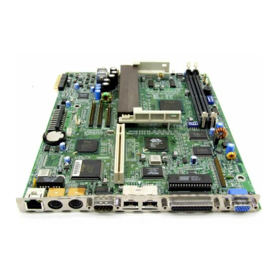
Page 13: Components On The System Board
Components on the system board Components on the system board 1 = Switching Regulator 7 = Hardware monitoring 2 = CLK Generator 8 = Flash ROM 3 = Intel chipset 440BX 9 = LAN Controller Intel 82558 4 = SGRAM 10 = Intel PIIX4 5 = Screen controller ATI Rage LT Pro 11 = Battery... -
Page 14: Ports, Connectors And Switch Blocks
Ports, connectors and switch blocks Ports, connectors and switch blocks 15 16 1 = Connector for power-on indicator (JP1) 17 = LAN connector (CN28) 2 = Connector for Turbo/LAN LED (JP5) 18 = Connector for slot board 3 = Connector for Wake-on-LAN (CN2) 19 = Connector for CD-in (CN25) 4 = Connector for Modem-ring-in (CN1) 20 = Connector for power supply (CN26) -
Page 15: Switch Block 1 - Settings And Functions
Ports, connectors and switch blocks The blackened pin of a jumper or a connector represents pin 1 The connectors marked do not have to be present on the system board. Switch block 1 - Settings and functions In the following paragraphs the settings and functions of the single switches of switch block 1 are explained (position No. -
Page 16: Possible Screen Resolution
Possible screen resolution Possible screen resolution Depending on the operating system used the screen resolutions in the following table refer to the screen controller on the system board. If you are using an external screen controller, you will find details of supported screen resolutions in the Operating Manual or Technical Manual supplied with the controller. -
Page 17: Upgrading Main Memory
Upgrading main memory Upgrading main memory The system board is equipped with two 168 pin sockets with which the main memory can be upgraded to a maximum of 256 Mbyte. These slots are suitable for 16, 32, 8, 64 and 128 Mbyte SDRAM memory modules of the DIMM format. -
Page 18: Replacing The Processor
Replacing the processor Replacing the processor Removing the Pentium II Ê Pull connector JP6 (connector for the On/Off switch, position No. 31 in figure "Ports, connectors and switch blocks"), and remember its plug-in position. Ê Pull connectors JP8 and JPX1 (connectors for temperature sensor and fan, position No. 26 and 30 in figure "Ports, connectors and switch blocks"), and remember their plug-in positions. -
Page 19: Replacing The Lithium Battery
Replacing the lithium battery Replacing the lithium battery Once you have installed the system board, you should remove the battery protection (i.e. the thin plastic plate between battery and contact spring). Incorrect replacement of the lithium battery may lead to a risk of explosion. The lithium battery must be replaced with an identical battery or a battery type recommended by the manufacturer (CR2032). - Page 20 Error messages PS/2 Pointing Device Interface Error Ê Check or replace the pointing device interface. Floppy Disk Controller Error Ê Check the floppy drive cable and its connections. Change the floppy disk controller or disable the onboard controller by installing another add-on board with a controller.
- Page 21 Error messages Expansion ROM Allocation Fail Ê Change the I/O expansion ROM address. Onboard Serial Port IRQ Conflict(s) Ê In BIOS Setup change the interrupt assignment for the onboard serial port or disable it. Onboard Parallel Port IRQ Conflict(s) Ê In BIOS Setup change the interrupt assignment for the onboard parallel port or disable it.
-
Page 23: Bios Setup
BIOS Setup In BIOS Setup you can set the system functions and the hardware configuration of the device. When it is supplied, the device is set to factory default settings. You can change these settings in BIOS Setup. Any changes you make take effect as soon as you save the settings and quit the BIOS Setup. -
Page 24: System Information
BIOS Setup As an advanced user you can call the Advanced level by pressing [F8] [F8] [F8] in the main menu. [F8] Additional parameters appear. These parameters are marked with asterisk (*) in this manual. The command line at the bottom of the menus tells you how to use BIOS Setup. Ê... -
Page 25: Product Information
BIOS Setup System Information Page 2/2 Serial Port ....... 3F8h, IRQ 4 Parallel Port ..... 378h, IRQ 7 PS/2 Mouse ......Installed Memory Parity Mode ....[Disabled] USB Host Controller ....[Enabled] PgDn/PgUp = Move Screen, Esc = Back to Main Menu Example for the 2. -
Page 26: Diskettes Drives
BIOS Setup Disk Drives Page 1/1 Diskette Drive A ..[1.44-MB 3.5-inch] Diskette Drive B ..[ None • *IDE Primary Channel Master • *IDE Primary Channel Slave • *IDE Secondary Channel Master • *IDE Secondary Channel Slave ↑↓ = Move Highlight Bar F1 = Help →... - Page 27 BIOS Setup Type This field is used to specify the type of hard disk drive. Auto configures the hard disk automatically. You do not need to select the parameters yourself. If you know your hard disk type, you can enter the setting manually with the Cylinder, Head, Sector and Size parameters. Number of cylinders Cylinder Head...
-
Page 28: Onboard Peripherals
BIOS Setup Onboard Peripherals In the Onboard Peripherals menu you can make the settings for the serial and parallel ports. In the Onboard Device Settings submenu you can make settings for specific onboard controller. To display Onboard Device Settings you must enter the main menu and switch to Advanced level with [F8] [F8] [F8] [F8]. -
Page 29: Onboard Device Settings
BIOS Setup Onboard Device Settings To display this parameter you must enter the main menu and switch to Advanced level with [F8] [F8]. [F8] [F8] Onboard Device Settings Page 1/1 Floppy Disk Controller ....[Enabled ] IDE Controller ...... [Both ] PS/2 Mouse Controller .... -
Page 30: Power Management
BIOS Setup Onboard Ethernet Chip This field is used to enable and disable the built-in Ethernet chip on the system board. The Ethernet controller is enabled. Enabled The Ethernet controller is disabled. Disabled Power Management In the Power Management menu you can set energy saving functions for your system. Programs for power management can change the settings for the energy saving functions. -
Page 31: System Wake-Up Event
BIOS Setup System Wake-Up Event Specifies the event which wakes up the system. Modem Ring Indicator This field specifies whether the system can be switched on by an incoming message (e.g. via modem, fax or telephone). The signal can be supplied externally via serial port 1 or internally via the Wake-on-LAN or the modem-ring-in connector. -
Page 32: Fast Boot
BIOS Setup Fast Boot Fast Boot can reduce the extent of the self-test and thus accelerate the system startup. Auto The fast self test is performed. Disabled When the device is switched on, the complete device configuration is tested. Silent Boot With Silent Boot you can display or hide the startup messages while the system is booting. -
Page 33: Date And Time
BIOS Setup Date and Time The Date and Time menu indicates the date / the time of the device. The date is entered in the weekday-month-day-year format. The time is entered in the hour-minute-second format. If you want to change the current date set / the current time set, enter the new date in the System Date field / the new time in the System Time field. - Page 34 BIOS Setup The Setup Password screen is displayed. Setup Password Page 1/1 Enter your new Password twice. Password may be up to 7 characters long. Enter Password ....[XXXXXXX] Enter Password again ... [XXXXXXX] Set or Change Password ↑↓ = Move Highlight Bar F1 = Help Esc = Exit Ê...
-
Page 35: Power-On Password
BIOS Setup Power-on Password With the system password you can prevent booting of the operating system. Only those who know the system password can access the system. You can set the system password in the Power-on Password field of the System Security menu. Follow the same procedure as in setting the Setup password. -
Page 36: Memory / Cache Options
BIOS Setup Memory / Cache Options Calls the submenu in which you can make the settings for main memory and cache. *Memory / Cache Options Page 1/1 Internal Cache (CPU Cache) .....[Enabled] *External Cache ......[Enabled] *Cache Scheme .......Write Back *Memory at 15MB - 16MB Reserved for ..[System] *Memory Parity Mode ....[Disabled] ↑↓... -
Page 37: Memory Parity Mode
BIOS Setup Memory Parity Mode Determines whether a parity check is carried out in the case of DRAM modules. If the system BIOS detects that at least one DRAM module does not have a parity bit, the parity check is generally disabled. No parity check is performed. -
Page 38: Pci Slot 1 / 2 / 3
BIOS Setup PCI Slot 1 / 2 / 3 If PCI IRQ Setting is set to Manual, you can set the PCI interrupts in this field. Multifunctional PCI boards or boards with an integrated PCI-to-PCI bridge can use several PCI interrupts (INTA#, INTB#, INTC#, INTD#). -
Page 39: Reset Resource Assignments
BIOS Setup Reset Resource Assignments This field specifies whether the configuration data is reset and reinitialized when the system is started. After the system is started, the configuration data is reset, and the entry in this field is set to No. The new configuration data is determined by means of the Plug&Play functionality. -
Page 41: Index
Index Abort Settings Change Accumulator Advanced Options Advanced system configuration Battery disposal replace BIOS Setup Abort Advanced shell advanced system configuration calling exiting loading defaults Main menu Standard shell Boot from LANDesk Service Agent Boot Options Boot over BOOTP Boot Sequence Cache Configuration Table Connector... - Page 42 Index Graphics controller, screen resolutions IDE drives Interfaces, onboard Internal Cache Lithium battery Load Default Settings Main memory upgrading Main menu Memory Memory / Cache Options Memory at 15MB-16MB Memory module installing removing Memory test Monitor controller Multifunctional PCI boards Notational conventions Num Lock After Boot Onboard controller...
- Page 43 Index Power management Power-on Password Primary Display Adapter Product Information Real-time clock module Recycling, battery Replacing the processor Reset Resource Assignments Screen resolutions Security functions Self test, reduced Setting bus frequency Setting date Setting display Setting floppy disk drive Setting the clock ratio Setting time Setup password Skipping password query...