Table of Contents
Advertisement
Quick Links
Advertisement
Table of Contents

Related Manuals for Extron electronics SW USB Series


Summary of Contents for Extron electronics SW USB Series
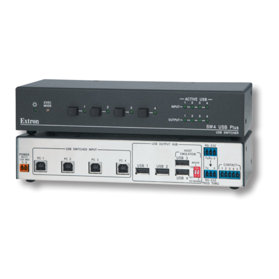
- Page 1 User Guide Switchers SW USB Series USB Switchers 68-1517-01 Rev.G 06 21...
- Page 3 Copyright © 2008-2021 Extron. All rights reserved. www.extron.com Trademarks All trademarks mentioned in this guide are the properties of their respective owners. The following registered trademarks ( ® ), registered service marks ( ), and trademarks ( ) are the property of RGB Systems, Inc. or Extron (see the current list of trademarks on the Terms of Use page at www.extron.com):...
- Page 4 FCC Class A Notice This equipment has been tested and found to comply with the limits for a Class A digital device, pursuant to part 15 of the FCC rules. The Class A limits provide reasonable protection against harmful interference when the equipment is operated in a commercial environment.
- Page 5 Conventions Used in this Guide Notifications The following notifications are used in this guide: WARNING: Potential risk of severe injury or death. AVERTISSEMENT : Risque potentiel de blessure grave ou de mort. CAUTION: Risk of minor personal injury. ATTENTION : Risque de blessure mineure.
-
Page 7: Table Of Contents
Contents Introduction ..........1 About this Guide ..........1 About the SW USB Series ........1 SIS Programming and Control ....27 Features .............. 1 Host-to-Switcher Communication ...... 27 USB System Architecture ........2 Switcher-initiated Messages ......27 Application Diagrams ........... 4 Error Responses .......... - Page 8 SW USB Series • Contents...
-
Page 9: Introduction
“switcher” are used throughout this guide to refer to all models. About the SW USB Series The SW USB Series switchers make it possible for two or four host computers to share and switch among up to four peripheral USB devices such as mass storage devices, keyboards, mice, and other human interface devices (HIDs). -
Page 10: Usb System Architecture
(or root hub) occupying the first tier. NOTE: Do not connect more than five daisy-chained hubs to the root hub. The architecture does not support peripheral devices connected to USB hubs occupying the seventh tier. SW USB Series • Introduction... - Page 11 NOTE: If the host device runs Windows or macOS™ operating systems, use the ® following programs to view the hierarchical relationships between USB devices: • Windows: Device Manager macOS: System Profiler or System Information • SW USB Series • Introduction...
-
Page 12: Application Diagrams
Application Diagrams The following diagrams show examples of how an SW USB Series switcher can be connected. id e t iv Extron V id t a l r iz SW4 USB ls e USB Switcher 1 Rx B 10 -2 32... - Page 13 A rs O TE R EM U TS IN P Extron SW4 VGA Ars VGA/Audio Switcher Flat Panel Display Figure 4. Connection Diagram for an SW4 USB Plus Switcher in a Keyboard-Video-Mouse (KVM) Switching Application SW USB Series • Introduction...
-
Page 14: Installation
Installation This section gives an overview of the steps to installing the SW USB Series switchers. It also provides a description of the rear panel connectors and instructions for cabling. The following topics are discussed: • Installation Overview Rear Panel Features •... -
Page 15: Rear Panel Features
Contact port — If desired, connect a two- or four-button contact closure device to this 3-pole (SW2) or 5-pole (SW4 models), 3.5 mm captive screw connector to enable Setting Up Contact Closure Control input selection via contact closure (see page 12). SW USB Series • Installation... -
Page 16: Wiring The Power Connector
Les deux cordons d’alimentation doivent être maintenus à l’écart tant que la source d’alimentation est branchée. To wire the power connector: Cut the DC output cord of the power supply to the length needed. Strip the jacket to expose 3/16 inch (5 mm) of the conductors. SW USB Series • Installation... - Page 17 Pour vérifier la polarité avant la connexion, brancher l’alimentation hors charge et mesurer sa sortie avec un voltmètre. SW USB Series • Installation...
- Page 18 • Si le produit n’est pas fourni avec une source d’alimentation, il doit être alimenté par une source d’alimentation certifiée UL de classe 2 ou LPS, avec une tension nominale 12 Vcc, 0.7 A minimum. SW USB Series • Installation...
-
Page 19: Wiring For Rs-232 Communication
Contact (closure) port, or the front panel input buttons through the RS-232 Pass Thru port to send SIS commands to another Extron AV switcher. NOTE: Only Extron products can be controlled via this port. SW USB Series • Installation... -
Page 20: Setting Up Contact Closure Control
Issue the SIS command E 0LOOP } to the SW USB to enable loop 0 mode (see Selecting the loop mode on page 18 for more information). Figure 7 App Diagram SW USB Series • Installation... -
Page 21: Connecting Multiple Sw Usbs In A System
NOTE: Do not exceed five cascaded hubs and a total of 127 peripheral devices in the entire system. Figure 9 on the next page shows an example of a single host with the maximum of five SW USB switchers cascaded in a series. SW USB Series • Installation... - Page 22 USB Flash Printer Drive Tier 5 ACTIVE USB EXEC MODE INPUT OUTPUT SW4 USB Plus USB SWITCHER Camera USB Flash Drive Figure 10. Example of a Host with Five SW USB Switchers Cascaded in a Series SW USB Series • Installation...
-
Page 23: Operation
Input Selection buttons and LEDs Figure 11. SW USB Series Front Panels Power LED — This green LED lights when the SW USB has power. Exec Mode LED — This red LED lights when the SW USB is in front panel lock mode,... -
Page 24: Operations
SW USB Contact port, press the button on the device that corresponds to the SW USB input that you want to select. The first button on the left selects input 1, the second button selects input 2, and so forth. SW USB Series • Operation... -
Page 25: Issuing Commands To An Extron Av Switcher Via The Rs-232 Pass Thru Port
NOTE: You can issue commands to the SW USB using the front panel buttons, RS-232, or contact closure in both loop modes. The loop mode selection affects only commands going through the RS-232 Pass Thru port to the AV switcher. SW USB Series • Operation... - Page 26 Passed through, not performed* CMD ] CMD ] Passed through, not performed* * For explanations of commands that are passed through to the AV switcher and not performed by the SW USB, see your AV switcher user guide. SW USB Series • Operation...
- Page 27 Function on the Closure via RS-232 Pass AV Switcher Selection Thru Select input 1 Pin 1 to Select input 2 Pin 2 to Select input 3 Pin 3 to Select input 4 Pin 4 to SW USB Series • Operation...
-
Page 28: Locking And Unlocking The Front Panel (Executive Mode)
Only a single hub or extender is supported. If a second hub or a second extender is connected, host emulation is disabled on one of the ports. SW USB Series • Operation... -
Page 29: Troubleshooting
DIP switches to Off, and then wait for the switcher to reboot. You are not able to use host emulation with that keyboard or mouse. SW USB Series • Operation... -
Page 30: Peripheral Emulation (Sw4 Usb Plus Only)
(if you need an Insider Account, see your Extron representative). Follow the instructions on the subsequent screens to complete the firmware program installation. By default, the firmware file is stored on your computer at C:\Program Files(x86)\Extron\Firmware\DSC 401. SW USB Series • Operation... - Page 31 Click the Browse button in the New Firmware File (Optional) section. On the Open window, navigate to the new firmware file, which has a S19 extension, and double-click it. Figure 14. Open Window for Firmware Loader SW USB Series • Operation...
- Page 32 C:\Program Files (x86)\Extron\Firmware\SW USB. On the Add Device window, the path to the new firmware file is displayed in the Path field. Figure 15. Add Device Window with an SW USB Switcher and Firmware File Selected SW USB Series • Operation...
- Page 33 The Total Progress panel displays a progress bar with Uploading... above it. • In the Devices panel, the Progress column displays an incrementing percentage • and another progress bar. The Status column displays Uploading. Figure 17. Firmware Upload in Progress SW USB Series • Operation...
- Page 34 Progress column shows 100%, and Completed is displayed above the progress bar and in the Status panel. Figure 18. Firmware Upload Complete When the firmware upload and unit reset are complete, close the Firmware Loader window. SW USB Series • Operation...
-
Page 35: Sis Programming And Control
SWn is the switcher model number as well as the number of inputs, and Vn.nn is the firmware version number. NOTE: This message is displayed only when power is applied to the switcher while it is connected to the computer. SW USB Series • SIS Programming and Control... -
Page 36: Error Responses
= Position of the keyboard emulation DIP switch (SW4 USB Plus only) 0 = Keyboard emulation off (DIP switch 2 is down.) 1 = Keyboard emulation on (DIP switch 2 is up.) NOTE: Unless otherwise indicated, commands are not case sensitive. SW USB Series • SIS Programming and Control... -
Page 37: Command And Response Table For Sis Commands
Query firmware version Show firmware version, expressed to the n.nn second decimal place. 1.01 Example: 1.01 The unit firmware version is n.nn.nnnn ] Query version and build Show firmware version and build number. SW USB Series • SIS Programming and Control... - Page 38 Reset the switcher to factory default ZXXX values. Upload Firmware Upload firmware Upload ...go appears after the upload is complete (see Updating Firmware on page 22 for information on the firmware updating process). SW USB Series • SIS Programming and Control...
-
Page 39: Reference Information
Reference Information Mounting the SW USB Series Switcher The SW USB Series switcher can be set on a table, mounted on a rack shelf, or mounted under a desk, podium, or table. Tabletop Use Four adhesive rubber feet are included with the SW USB switcher. For tabletop use, attach one foot at each corner on the bottom of the unit, and place the switcher in the desired location. - Page 40 If rubber feet were previously attached to the bottom of the unit, remove them. Remove the two screws from one side of the SW USB. Retain the screws for possible later reassembly. Attach the brackets to the sides of the unit, using the provided machine screws. SW USB Series • Reference Information...
- Page 41 Align the mounting screws with the slots in the brackets and place the unit against the surface, with the screws through the bracket slots. Figure 21. Mounting the SW USB under Furniture Slide the unit slightly forward or back, then tighten all four screws to secure it in place. SW USB Series • Reference Information...
- Page 42 Extron Warranty Extron warrants this product against defects in materials and workmanship for a period of three years from the date of purchase. In the event of malfunction during the warranty period attributable directly to faulty workmanship and/ or materials, Extron will, at its option, repair or replace said products or components, to whatever extent it shall deem necessary to restore said product to proper operating condition, provided that it is returned within the warranty period, with proof of purchase and description of malfunction to: USA, Canada, South America,...
Need help?
Do you have a question about the SW USB Series and is the answer not in the manual?
Questions and answers