Advertisement
Available languages
Available languages
Quick Links
PowPak
| Installation
TM
Relay Module
Part of the Energi TriPak
Family
TM
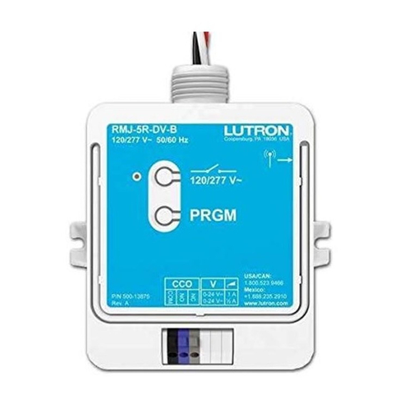
RMJ-5R-DV-B
120 / 277 V~ 50 / 60 Hz 5 A
1/6 HP at 120 V~ 1/3 HP at 277 V~
RMJ-5RCCO1-DV-B
With Occupancy-Status CCO
Important Notes:
Please read before installing.
•
For installation by a qualified electrician in accordance with all local and
national electrical codes.
•
Note: Use copper conductors only.
•
Check to see that the device type and rating is suitable for the application.
•
DO NOT install if product has any visible damage.
•
If moisture or condensation is evident, allow the product to dry completely
before installation.
•
Operate between 32 °F (0 °C) and 104 °F (40 °C).
•
0% to 90% humidity, non-condensing.
•
For indoor use only.
WARNING
Shock Hazard. May result in serious injury or death.
Turn off power at circuit breaker before installing the unit.
PowPak
TM
Relay Module
Install in center of room to
maximize RF coverage.
Radio
Powr Savr
TM
Occupancy
Sensor
30 ft (10 m)
Maximum
Pico
®
Wireless
Transmitter
40 ft (12 m)
All Wireless Transmitters must be installed within
30 ft (10 m) of the PowPak
Relay Module.
TM
CCO Information
• Model RMJ-5RCCO1-DV-B includes a dry contact
closure output that provides occupancy status to
3rd-party equipment such as building management
systems, HVAC, and VAV controllers.
• CCO provides both normally open (NO) and normally
closed (NC) maintained-type outputs.
• CCO rated to switch resistive loads at voltages up
to 24 V only. To properly control inductive load
types such as relays, solenoids, or motors, refer
to Application Note #434.
Switching
Resistive
Voltage
Load
R
0-24 V-
1.0 A
0-24 V~
0.5 A
Lutron Electronics Co., Inc.
7200 Suter Road | Coopersburg, PA 18036-1299
Required Components
For each system ensure you have:
At Least One PowPak
Relay Module.
041-345
TM
Rev. A
(RMJ-5RCCO1-DV-B Shown)
08/2011
Load
Status
LED
Relay Toggle
Advanced
Operations
Contact
Closure
RMJ-5R-DV-B without
Output
occupancy-status CCO
(CCO)
also available.
(Class 2)
PowPak
Relay Module
TM
Start Here
1
Install PowPak
TM
Relay Module
When installing a PowPak
Relay
TM
Module, use the supplied conduit nut
and wire the module as shown.
Suggested Installation Location:
Install in center of room.
This ensures proper RF coverage of area.
If installing unit inside a junction box please
see Application Note #423.
For more information:
www.lutron.com/powpakrelay
2
Associate Wireless Transmitters to PowPak
Before beginning this step, make sure that there are no other PowPak
from other systems can be incorrectly associated to this system.
A
Hold the Relay Toggle
button on the PowPak
Relay Module for 6 seconds
to enter association mode.
Note: The load will flash once
after each step to confirm
successful completion.
Permanently Install
3
Wireless Transmitters
Link
Test
Note: Please consult individual
component installation guides
for information.
Need Help? www.lutron.com or call the Lutron Technical Support Center, 24/7 at 1.800.523.9466
At least one Wireless Transmitter.
+
Radio Powr Savr
Pico
TM
Occupancy Sensor
Transmitter
(6 maximum)
(9 maximum)
120/277 V~
50/60 Hz
Red
(Switched Hot)
COM
(Common)
NC
NO
(Normally Closed)
(Normally Open)
CCO operation affected only by
associated occupancy or vacancy sensors.
Room Occupied:
NO = Close NC = Open
Room Unoccupied: NO = Open NC = Close
Relay Module
TM
modules being set up within the same building. It is possible that Wireless Transmitters
TM
B
Hold the indicated button on a Wireless Transmitter for
6 seconds to associate the device.
TM
Repeat for any additional Wireless Transmitters.
Hold the Relay Toggle button on the PowPak
C
Relay Module for 6 seconds to save association(s).
4
Daylight Sensor Setup
Calibration
Link
Cal.
Test
A
Turn lights in room on using the
A
Relay Toggle button on the PowPak
TM
Relay Module or an associated Pico
.
®
B
Press & hold "Cal." on the associated
Daylight Sensor for 6 seconds.
C
Exit room for 5 minutes to allow
calibration to be completed.
Link
Cal.
Test
Radio Powr Savr
Wireless
TM
®
Daylight Sensor
(1 maximum)
White
(Neutral)
To Load
Black
(Hot)
Conduit Nut
To 3rd Party Equipment
Note: When wiring RMJ-5RCCO1-DV-B
to 3rd-party systems, use 20 to 16 AWG
(0.5 to 1.5 mm
) solid or stranded wire.
2
Cal.
Link
Test
TM
Tuning (Optional)
If it is desired to have multiple zones of lights
turn on at different daylight levels (using multiple
Relay Modules with one Daylight Sensor) follow
the Tuning procedure described in the Daylight
Sensor's installation instructions (041-277).
Use the Relay Toggle button in place of the
Dimmer/Switch tap button referenced in
the document.
FCC Information:
This device complies with part 15 of the FCC Rules and Industry
Canada licence-exempt RSS standard(s). Operation is subject to
the following two conditions:
(1) This device may not cause interference, and
(2) this device must accept any interference, including
interference that may cause undesired operation.
Modifications not expressly approved by Lutron Electronics Co., Inc.
could void the user's authority to operate this equipment.
NOTE: This equipment has been tested and found to comply with the
limits for a Class B digital device, pursuant to part 15 of the FCC Rules.
These limits are designed to provide reasonable protection against harmful
interference in a residential installation. This equipment generates, uses
and can radiate radio frequency energy and, if not installed and used in
accordance with the instructions, may cause harmful interference to radio
communications. However, there is no guarantee that interference will
not occur in a particular installation. If this equipment does cause harmful
interference to radio or television reception, which can be determined by
turning the equipment off and on, the user is encouraged to try to
correct the interference by one or more of the following measures:
• Reorient or relocate the receiving antenna.
• Increase the separation between the equipment and receiver.
• Connect the equipment into an outlet on a circuit different from that to
which the receiver is connected.
Limited Warranty
(Valid only in U.S.A., Canada, Puerto Rico, and the Caribbean.)
Lutron will, at its option, repair or replace any unit that is defective in
materials or manufacture within one year after purchase. For waranty
service, return unit to place of purchase or mail to Lutron at 7200 Suter
Rd., Coopersburg, PA 18036-1299, postage pre-paid.
This warranty is in lieu of all other express warranties, and the implied
warranty of merchantability is limited to one year from purchase. This
warranty does not cover the cost of installtion, removal or reinstallation,
or damage resulting from misuse, abuse, or damage from improper
wiring or installation. This warranty does not cover incidental or
consequential damages.
LUTRON'S LIABILITY ON ANY CLAIM FOR DAMAGES ARIS-
ING OUT OF OR IN CONNECTION WITH THE MANUFACTURE,
SALE, INSTALLATION, DELIVERY, OR USE OF THE UNIT SHALL
NEVER EXCEED THE PURCHASE PRICE OF THE UNIT.
This warranty gives you specific legal rights, and you may have other
rights which vary from state to state. Some states do not allow the
exclusion or limitation of incidental or consequential damages, or
limitation on how long an implied warranty may last, so the above
limitations may not apply to you. Lutron, the Sunburst Logo and Pico
are registered trademarks and PowPak, Radio Powr Savr and Energi
TriPak are trademarks of Lutron Electronics Co., Inc.
©2011 Lutron Electronics Co., Inc.
Reset Factory Defaults
Note: In some instances it may be necessary to reset the
PowPak
Relay Module back to factory default settings.
TM
A
Triple-tap the Advanced Operations button, "ADV"
on the PowPak
Relay Module and hold until the
TM
LED begins to flash slowly.
B
Within 3 seconds of flashing, release and triple-tap
the button again and the LED will flash rapidly
indicating that the unit has been reset to
factory defaults.
Note: Any associations or programming previously set
up with the unit will be lost and will need to be
re-programmed.
Troubleshooting
www.lutron.com
Load does
• Ensure breaker to the PowPak
Relay
TM
not respond
Module is on.
to Wireless
• Ensure the load has been properly wired
Transmitter(s).
to the PowPak
Relay Module.
TM
• Ensure Wireless Transmitter is properly
associated to PowPak
Relay Module.
TM
• Ensure Wireless Transmitter's battery is
installed correctly.
Wireless
• The maximum number of Wireless
Transmitters have been associated
Transmitter(s)
to the PowPak
Relay Module. To
cannot be
TM
remove a previously set up Wireless
associated to
Transmitter, tap the button used for
PowPak
TM
association on the Wireless Transmitter
Relay Module.
three times, on the third tap hold for
three seconds and then tap three
more times.
Advertisement

Related Manuals for Lutron Electronics PowPak RMJ-5R-DV-B


Summary of Contents for Lutron Electronics PowPak RMJ-5R-DV-B
- Page 1 RMJ-5RCCO1-DV-B Relay Toggle Modifications not expressly approved by Lutron Electronics Co., Inc. With Occupancy-Status CCO could void the user’s authority to operate this equipment. NOTE: This equipment has been tested and found to comply with the...
- Page 2 RMJ-5RCCO1-DV-B l’interférence qui peut affecter le fonctionnement. Commutation Avec Occupation-Statut CCO Les modifications non expressément approuvées par Lutron Electronics Co., de relais Inc. pourront annuler le droit de l’utilisateur à faire fonctionner cet équipement. Remarques importantes : REMARQUE : Cet équipement a été testé et est en conformité avec les Opérations...
Need help?
Do you have a question about the PowPak RMJ-5R-DV-B and is the answer not in the manual?
Questions and answers