
Related Manuals for Silvus StreamCaster 4000 Series


Summary of Contents for Silvus StreamCaster 4000 Series
- Page 1 StreamCaster 4000 series MIMO Radio User Manual Document Number 10017C000 Version 4.0.0.1 Date 9/2/2020 Silvus Technologies, Inc. 10990 Wilshire Blvd, #1500 Los Angeles, CA 90024...
- Page 2 StreamCaster 4000 series MIMO Radio User Manual Notice Silvus Technologies reserves the right to make changes to its products or discontinue any of its products or offerings without notice. Silvus Technologies warrants the performance of its products to the specifications applicable at the time of sale in accordance with Silvus Technologies’...
-
Page 3: Table Of Contents
9/2/20 StreamCaster 4000 series MIMO Radio User Manual Contents General Safety Information ......................10 Health & Safety........................ 10 Maximum RF Power Density Limits ................... 13 Introduction ..........................14 StreamCaster Network ......................14 StreamCaster Hardware Overview ....................15 Hardware Interfaces ......................15 SC4400E .......................... - Page 4 9/2/20 StreamCaster 4000 series MIMO Radio User Manual 5.1.4 Serial/USB Setup (not available on IVAS) ............... 73 5.1.5 PTT (push-to-talk) (not available on IVAS).............. 76 StreamScape Network Configuration ................78 5.2.1 Network Topology ....................78 5.2.2 Mapping......................87 5.2.3 Table View ......................95 5.2.4...
- Page 5 9/2/20 StreamCaster 4000 series MIMO Radio User Manual 7.2.1 Implementation ....................129 7.2.2 Use Case ......................129 Custom Frequency Plan ......................131 Accessing and Installing CFP ................... 131 Streaming Response ........................ 134 RSSI and Noise Floor Reporting ..................135 Temperature Reporting ....................138 Voltage Reporting ......................
- Page 6 9/2/20 StreamCaster 4000 series MIMO Radio User Manual 15.6 Radiation Exposure Statement: English ................154 15.7 Radiation Exposure Statement: French................154 10017C000 Silvus Technologies Confidential Page...
- Page 7 9/2/20 StreamCaster 4000 series MIMO Radio User Manual List of Figures Figure 1 Product Symbols with Definition ..................12 Figure 2 StreamCaster 4400E Ruggedized Enclosure ................15 Figure 3 StreamCaster 4200E Ruggedized Enclosure ................17 Figure 4 StreamCaster 4400 Ruggedized Enclosure ................19 Figure 5 StreamCaster 4200 Ruggedized Enclosure ................
- Page 8 Figure 35 Serial/USB Setup Page – RS-232 ..................73 Figure 36 Serial/USB Setup Page – Serial Relay.................. 73 Figure 37 Push-to-Talk (PTT) & Audio Page..................76 Figure 38 Silvus StreamScape Network Topology Page ..............79 Figure 39 Example Network Topology ....................79 Figure 40 Individual Node Characteristics..................82 Figure 41 Link Characteristics ......................
- Page 9 9/2/20 StreamCaster 4000 series MIMO Radio User Manual Figure 66 Security (Encryption) ....................... 105 Figure 67 Security (SSH/HTTPS Certificates) ..................107 Figure 68 (Chrome Browser Warning) ..................... 108 Figure 69 Security (White/Black List) ....................109 Figure 70 Admin page........................110 Figure 71 Login..........................
- Page 10 9/2/20 StreamCaster 4000 series MIMO Radio User Manual List of Tables Table 1 Safe Working Distances ......................11 Table 2 SC4400E Primary Power/Ethernet/Serial Connector Pinout ........... 21 Table 3 SC4400E Serial and GPS Pinout ..................... 22 Table 4 SC4400E USB/GPIO Connector Pinout ................... 23 Table 5 SC4400E PTT Connector Pinout .....................
-
Page 11: General Safety Information
It is important to note that the guidelines adopted differ throughout the world and are from time-to-time re-issued with revised guidelines. For Silvus use, a maximum power density limit of 1w/m² is to be applied when calculating minimum safe working distances. -
Page 12: Table 1 Safe Working Distances
9/2/20 StreamCaster 4000 series MIMO Radio User Manual To be safe: a) Operators should not stand or walk in front of any high gain antenna such as dish antennas, nor should they allow anyone else to do so. b) Operators should not operate any RF transmitter or power amplifier with any of its covers removed, nor should they allow anyone else to do so. -
Page 13: Figure 1 Product Symbols With Definition
9/2/20 StreamCaster 4000 series MIMO Radio User Manual Figure 1 Product Symbols with Definition • Product cleaning should only be done with a soft cloth and mild detergent, do not use any solvents that might remove case markings or labels. -
Page 14: Maximum Rf Power Density Limits
/ frequency characteristics are presented in the two documents. To avoid complexity and to avoid areas of uncertainty, Silvus recommends the use of a single power density limit across the frequency range 100 kHz to 300 GHz. The 1w/m² power density limit we recommend satisfies the most stringent of the guidelines published to date. -
Page 15: Introduction
9/2/20 StreamCaster 4000 series MIMO Radio User Manual 2. Introduction The StreamCaster family of MIMO radios was designed with operator ease of use in mind. Each radio is capable of operating in a multitude of configurations that are accessed via simple web pages within the radio. -
Page 16: Streamcaster Hardware Overview
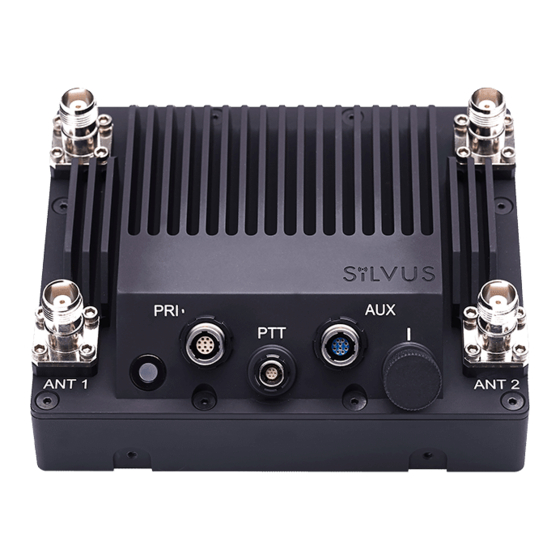
9/2/20 StreamCaster 4000 series MIMO Radio User Manual 4. StreamCaster Hardware Overview Hardware Interfaces SC4400E Figure 2 StreamCaster 4400E Ruggedized Enclosure RF Channels 1-4 Connectors [TNC Female] Bi-Color Status LED • Red – Radio is in the process of booting up •... - Page 17 9/2/20 StreamCaster 4000 series MIMO Radio User Manual Power (9-20V), Ethernet, and Serial Port Connector [ODU GK0YAR-P10UC00-000L] Push-to-Talk (PTT) Connector [ODU GKCWAM-P07UB00-000L] AUX Connector [ODU GK0YCR-P10UC00-000L] Power Switch [15-Position Rotating] 10017C000 Silvus Technologies Confidential Page 16...
-
Page 18: Sc4200E
9/2/20 StreamCaster 4000 series MIMO Radio User Manual SC4200E Figure 3 StreamCaster 4200E Ruggedized Enclosure RF Channels 1-2 Connectors [TNC Female] Power Switch [15-Position Rotating] Power (EB Version Only, 9-20V), Ethernet, and Serial Port Connector [ODU GK0YAR-P10UC00-000L] Bi-Color Status LED •... - Page 19 9/2/20 StreamCaster 4000 series MIMO Radio User Manual • Rapid Flashing Green – When the multi position switch is rotate to a new position, LED will rapidly flash green while new settings are being applied. LED will resume normal indication after settings have been applied.
-
Page 20: Sc4400
9/2/20 StreamCaster 4000 series MIMO Radio User Manual SC4400: Figure 4 StreamCaster 4400 Ruggedized Enclosure RF Channels 1-4 Connectors [TNC Female] Bi-Color Status LED • Red – Radio is in the process of booting up • Flashing Green – Radio is fully booted but not wirelessly connected to any other radio •... -
Page 21: Sc4200
9/2/20 StreamCaster 4000 series MIMO Radio User Manual SC4200: Figure 5 StreamCaster 4200 Ruggedized Enclosure RF Channels 1-2 Connectors [TNC Female] Power Switch [2-Position Rotating] Power (EB Version Only, 9-20V), Ethernet, and Serial Port Connector [Hirose LF10WBRB-12PD] Bi-Color Status LED •... -
Page 22: Connector Pinouts
9/2/20 StreamCaster 4000 series MIMO Radio User Manual Connector Pinouts 4.2.1 SC4400E Pinouts SC4400E Primary Power/Ethernet/Serial Connector Pinout Color of wires Enclosure PWR/COMM Switchcraft Pinout Signal coming from (GK0YAR-P10UC00-000L) (EN3C2F16X) ODU connector 5V OUT (For External GPS Puck) Pink GND IN... -
Page 23: Figure 7 Switchcraft Connector On Primary/Power Cable
9/2/20 StreamCaster 4000 series MIMO Radio User Manual SC4400E RS-232 Pinout RS-232 (DB9) Signal Switchcraft Pinout 5V OUT Ground Table 3 SC4400E Serial and GPS Pinout Figure 7 Switchcraft connector on Primary/Power cable 10017C000 Silvus Technologies Confidential Page 22... -
Page 24: Figure 8 Sc4400E Aux Pinout Diagram (Radio Side)
9/2/20 StreamCaster 4000 series MIMO Radio User Manual SC4400E AUX Connector Pinout Enclosure AUX Color of wires coming from Signal ODU connector (GK0YCR-P10UC00-000L) USB GND Yellow/Blue USB1_D- USB1_VBUS Green USB0_VBUS Violet GPIO1 (BDA control) Pink USB0_D+ Black USB0_D- Brown Light Green... -
Page 25: Figure 9 Sc4400E Ptt Pinout Diagram (Cable Side)
9/2/20 StreamCaster 4000 series MIMO Radio User Manual SC4400E PTT Connector Enclosure PTT Connector Signal (ODU GKCWAM-P07UB00-000L) 5V_OUT (Up to 400mA) COR/DUAL_PTT AUDIO_GND SPEAKER_OUT MIC_IN RESERVED (Do Not Connect) Table 5 SC4400E PTT Connector Pinout Figure 9 SC4400E PTT Pinout Diagram (Cable Side) -
Page 26: Sc4200E Pinouts
9/2/20 StreamCaster 4000 series MIMO Radio User Manual 4.2.2 SC4200E Pinouts SC4200E Primary Power/Ethernet/Serial Connector Pinout Color of wires Enclosure PWR/COMM Switchcraft Pinout Signal coming from (GK0YAR-P10UC00-000L) (EN3C2F16X) ODU connector 5V OUT (For External GPS Puck) Pink GND IN Yellow/Blue... - Page 27 9/2/20 StreamCaster 4000 series MIMO Radio User Manual 10017C000 Silvus Technologies Confidential Page 26...
-
Page 28: Figure 11 Switchcraft Connector On Primary/Power Cable
9/2/20 StreamCaster 4000 series MIMO Radio User Manual SC4200E RS-232 Pinout RS-232 (DB9) Signal Switchcraft Pinout 5V OUT Ground Table 7 SC4200E Serial and GPS Pinout Figure 11 Switchcraft connector on Primary/Power cable 10017C000 Silvus Technologies Confidential Page 27... -
Page 29: Figure 12 Sc4200E Aux Pinout Diagram (Radio Side)
9/2/20 StreamCaster 4000 series MIMO Radio User Manual SC4200E AUX Connector Pinout Enclosure AUX Color of wires coming from Signal ODU connector (GK0YCR-P10UC00-000L) USB GND Yellow/Blue USB1_D- USB1_VBUS Green USB0_VBUS Violet GPIO1 (BDA control) Pink USB0_D+ Black USB0_D- Brown Light Green... -
Page 30: Figure 13 Sc4200E Ptt Pinout Diagram (Cable Side)
9/2/20 StreamCaster 4000 series MIMO Radio User Manual SC4200E PTT Connector Enclosure PTT Connector Signal (ODU GKCWAM-P07UB00-000L) 5V_OUT (Up to 400mA) COR/DUAL_PTT AUDIO_GND SPEAKER_OUT MIC_IN RESERVED (Do Not Connect) Table 9 SC4200E PTT Connector Pinout Figure 13 SC4200E PTT Pinout Diagram (Cable Side) -
Page 31: Sc4400 Pinouts
9/2/20 StreamCaster 4000 series MIMO Radio User Manual 4.2.3 SC4400 Pinouts SC4400 Power/Ethernet/Serial Connector Pinout Enclosure PWR/COMM Switchcraft Pinout Signal (LF10WBRB-12PD) (EN3C2F16X) 5V OUT (For External GPS Puck) GND IN GND IN VCC IN VCC IN 100-Base T ETH0 M2N (RX-) -
Page 32: Figure 14 Sc4400 Power (Optional)/Serial/Ethernet Pinout Diagram (Cable Side)
9/2/20 StreamCaster 4000 series MIMO Radio User Manual Figure 14 SC4400 Power (Optional)/Serial/Ethernet Pinout Diagram (Cable Side) 10017C000 Silvus Technologies Confidential Page 31... -
Page 33: Figure 15 Sc4400 Aux Pinout Diagram (Cable Side)
9/2/20 StreamCaster 4000 series MIMO Radio User Manual SC4400 AUX Connector Pinout Enclosure AUX Signal (LF10WBRB-12SD) USB1_GND USB1_D- USB1_VBUS USB2_VBUS GPIO1 (PA Enable 3.3V) USB2_D+ USB2_D- RESERVED (Do Not Connect) USB1_Sense USB1_D+ USB2_GND Table 12 SC4400 AUX USB/GPIO Connector Pinout (USB1 is USB 2.0 OTG, USB2 is USB 2.0 Host Mode Only) -
Page 34: Figure 16 Sc4400 Ptt Pinout Diagram (Cable Side)
9/2/20 StreamCaster 4000 series MIMO Radio User Manual SC4400 PTT Connector Enclosure PTT Connector Signal (ODU GKCWAM-P07UB00-000L) RESERVED (Do Not Connect) RESERVED (Do Not Connect) AUDIO_GND SPEAKER_OUT MIC_IN RESERVED (Do Not Connect) Table 13 SC4400 PTT Connector Pinout Figure 16 SC4400 PTT Pinout Diagram (Cable Side) -
Page 35: Sc4200 Pinouts
9/2/20 StreamCaster 4000 series MIMO Radio User Manual 4.2.4 SC4200 Pinouts SC4200 Power/Ethernet/Serial Connector Pinout Enclosure PWR/COMM Switchcraft Pinout Signal (LF10WBRB-12PD) (EN3C2F16X) 5V OUT (For External GPS Puck) GND IN (External Power Option Only) GND IN (External Power Option Only) -
Page 36: Figure 17 Sc4200 Primary Power/Serial/Ethernet Pinout Diagram (Cable Side)
9/2/20 StreamCaster 4000 series MIMO Radio User Manual Grey Grey Black Switchcraft female EN3C6FX Serial Rx V+ for GPS Antenna - viewed from front Brown White White White Raised Ground RJ45 Pin 3 Indicates Pin #1 Purple Serial Tx Blue... -
Page 37: Figure 18 Sc4200 Aux Pinout Diagram (Cable Side)
9/2/20 StreamCaster 4000 series MIMO Radio User Manual SC4200 AUX Connector Pinout Enclosure AUX Signal (LF10WBRB-12SD) USB1_GND USB1_D- USB1_VBUS USB2_VBUS GPIO1 (PA Enable 3.3V) USB2_D+ USB2_D- RESERVED (Do Not Connect) USB1_Sense USB1_D+ USB2_GND Table 16 SC4200 AUX USB/GPIO Connector Pinout (USB1 is USB 2.0 OTG, USB2 is USB 2.0 Host Mode Only) -
Page 38: Figure 19 Sc4200 Ptt Pinout Diagram (Cable Side)
9/2/20 StreamCaster 4000 series MIMO Radio User Manual SC4200 PTT Connector Enclosure PTT Connector Signal (ODU GKCWAM-P07UB00-000L) RESERVED (Do Not Connect) RESERVED (Do Not Connect) AUDIO_GND SPEAKER_OUT MIC_IN RESERVED (Do Not Connect) Table 17 SC4200 PTT Connector Pinout Figure 19 SC4200 PTT Pinout Diagram (Cable Side) -
Page 39: Mechanical And Operating Specifications
9/2/20 StreamCaster 4000 series MIMO Radio User Manual Mechanical and Operating Specifications SC4400E: Mechanical • -40° to +65° C Ambient Temp. • IP-68 (Dust / Submersible in Water to 20m)** IP Rating • 5.25” x 4.5” x 1.8” (Excluding Connectors) Dimensions •... - Page 40 9/2/20 StreamCaster 4000 series MIMO Radio User Manual SC4200E: Mechanical • -40° to +65° C Ambient Temp. • IP-68 (Dust / Submersible in Water up to 20m)** IP Rating • 4.00” x 2.63” x 1.51” (Excluding Connectors) Dimensions • 0.94 lbs. (15 oz./0.43 kg.) Weight •...
- Page 41 9/2/20 StreamCaster 4000 series MIMO Radio User Manual SC4400: Mechanical • -40° to +65° C Ambient Temp. • IP-67 (Dust / Immersion in Water up to 1m)** IP Rating • 5.25” x 4.5” x 1.8” (Excluding Connectors) Dimensions • 2.5 lbs. (40 oz./1.13 kg.) Weight •...
- Page 42 9/2/20 StreamCaster 4000 series MIMO Radio User Manual SC4200: Mechanical • -40° to +65° C Ambient Temp. • IP-67 (Dust / Immersion in Water up to 1m)** IP Rating • 4.00” x 2.63” x 1.51” (Excluding Connectors) Dimensions • 0.94 lbs. (15 oz./0.43 kg.) Weight •...
-
Page 43: Sc4400E Enclosure Mechanical Drawing
9/2/20 StreamCaster 4000 series MIMO Radio User Manual 4.3.1 SC4400E Enclosure Mechanical Drawing Figure 20 SC4400E Mechanical Drawing (top) and Mounting Pattern (bottom) *Tapped mounting holes are available on bottom (8-32) and on the sides (4-40) of radio as indicated in Figure 20 SC4400E Mechanical Drawing (top) and Mounting Pattern (bottom). -
Page 44: Sc4200E Enclosure Mechanical Drawing
9/2/20 StreamCaster 4000 series MIMO Radio User Manual 4.3.2 SC4200E Enclosure Mechanical Drawing Figure 21 SC4200E Mechanical Drawing (top) and Mounting Pattern (bottom) *mounting holes utilize https://www.mcmaster.com/96006a234 or equivalent. Hex head (5/64” drive), 2 -56 thread, head diameter 9/64”; stainless steel; 3/8” length or longer... -
Page 45: Sc4400 Enclosure Mechanical Drawing
9/2/20 StreamCaster 4000 series MIMO Radio User Manual 4.3.3 SC4400 Enclosure Mechanical Drawing Figure 22 SC4400 Mechanical Drawing (top) and Mounting Pattern (bottom) *Tapped mounting holes are available on bottom (8-32) and on the sides (4-40) of radio as indicated in Figure 22 SC4400 Mechanical Drawing (top) and Mounting Pattern (bottom). -
Page 46: Sc4200 Enclosure Mechanical Drawing
9/2/20 StreamCaster 4000 series MIMO Radio User Manual 4.3.4 SC4200 Enclosure Mechanical Drawing Figure 23 SC4200 Mechanical Drawing (top) and Mounting Pattern (bottom) *mounting holes utilize https://www.mcmaster.com/96006a234 or equivalent. Hex head (5/64” drive), 2 -56 thread, head diameter 9/64”; stainless steel; 3/8” length or longer... -
Page 47: Sc4400E Specifications
9/2/20 StreamCaster 4000 series MIMO Radio User Manual SC4400E Specifications General • Mobile Networked MIMO (MN-MIMO™) Waveform • BPSK, QPSK, 16-QAM, 64-QAM Modulation • 5, 10 & 20 MHz (1.25*, 2.5*) Channel Bandwidth • DES Standard, AES/GCM 128/256 Optional (FIPS 140-2),... -
Page 48: Sc4200E Specifications
9/2/20 StreamCaster 4000 series MIMO Radio User Manual SC4200E Specifications General • Mobile Networked MIMO (MN-MIMO™) Waveform • BPSK, QPSK, 16-QAM, 64-QAM Modulation • 5, 10 & 20 MHz (1.25*, 2.5*) Channel Bandwidth • DES Standard, AES/GCM 128/256 Optional (FIPS 140-2),... - Page 49 9/2/20 StreamCaster 4000 series MIMO Radio User Manual SC4400E/SC4200 PTT Supported Mic Type Moving Coil or Condenser (Software Configurable) • Max Avg. Speaker Output Power Specifications 2.65W with 4 Ohm Speaker Impedance • MIC Bias 2.15V or 3V (Software Configurable); Applied via a 2K Ohm Resistor •...
-
Page 50: Sc4400 Specifications
9/2/20 StreamCaster 4000 series MIMO Radio User Manual SC4400 Specifications General • Mobile Networked MIMO (MN-MIMO™) Waveform • BPSK, QPSK, 16-QAM, 64-QAM Modulation • 5, 10 & 20 MHz (1.25*, 2.5*) Channel Bandwidth • DES Standard, AES/GCM 128/256 Optional (FIPS 140-2),... -
Page 51: Sc4200 Specifications
9/2/20 StreamCaster 4000 series MIMO Radio User Manual SC4200 Specifications General • Mobile Networked MIMO (MN-MIMO™) Waveform • BPSK, QPSK, 16-QAM, 64-QAM Modulation • 5, 10 & 20 MHz (1.25*, 2.5*) Channel Bandwidth • DES Standard, AES/GCM 128/256 Optional (FIPS 140-2),... - Page 52 9/2/20 StreamCaster 4000 series MIMO Radio User Manual SC4400/SC4200 PTT Supported Mic Type Specifications Moving Coil or Condenser (Software Configurable) • Max Avg. Speaker Output Power 2.65W with 4 Ohm Speaker Impedance • MIC Bias 2.15V or 3V (Software Configurable); Applied via a 2K Ohm Resistor •...
-
Page 53: Web Interface
9/2/20 StreamCaster 4000 series MIMO Radio User Manual 5. Web Interface Getting Started Connect a laptop to the StreamCaster radio using the USB-C to USB-A/USB-C cable (On one end of the cable is a USB-C connector that attaches to the radio. The other end has a USB-C connector that is used to supply power to the radio, and a USB-A connector which is meant to connect to a computer/device ) and turn on the radio. -
Page 54: Local Radio Configuration
9/2/20 StreamCaster 4000 series MIMO Radio User Manual Local Radio Configuration The first group of configurations on the left side of the GUI is the Local Radio Configurations. This group of parameters can help adjust your network to perform better in various environments, conditions, and applications. - Page 55 9/2/20 StreamCaster 4000 series MIMO Radio User Manual • Network ID: Network ID allows for clusters of radios to operate in the same channel, but remain independent. A radio with a given Network ID will only communicate with other radios with the same Network ID.
-
Page 56: Figure 26 Advanced Configuration Page
9/2/20 StreamCaster 4000 series MIMO Radio User Manual 5.1.1.2 Advanced Figure 26 Advanced Configuration Page This page is used to set the advanced settings. A brief description of each parameter is given below. MAC Settings: • Routing Beacon Period: Controls how often routing beacons are sent to other radios. A lower Routing Beacon Period results in faster reaction to topology changes. - Page 57 9/2/20 StreamCaster 4000 series MIMO Radio User Manual • Routing Beacon MCS: Select the MCS that routing beacons are sent at. Higher MCS values require less network overhead and may be beneficial for larger networks. The drawback is that the link will break when the Routing Beacon MCS can no longer be supported.
- Page 58 9/2/20 StreamCaster 4000 series MIMO Radio User Manual • Beamforming (SC4200/SC4400/IVAS): Enable or disable TX Beamforming (Up to 2X increase in range when enabled) • Transmit Channels: Allows user to Enable or Disable each channel on the radio for TX.
-
Page 59: Table 18 Mcs Vs. Sensitivity Chart (5Mhz Bandwidth)
9/2/20 StreamCaster 4000 series MIMO Radio User Manual Modulation Modes and Receiver Sensitivity • Note that listed sensitivity values were measured using a controlled and cabled setup. Actual results may vary by +/- 2dB. Table assumes link distance of 5000m. 10ms, 20ms, and 40ms burst time for 20, 10, and 5MHz bandwidth respectively. -
Page 60: Table 19 Mcs Vs. Sensitivity Chart (10Mhz Bandwidth)
9/2/20 StreamCaster 4000 series MIMO Radio User Manual PHY Throughput UDP User Throughput SC4400/3500/3800 SC4200/3822 Coding Rate (Mbps) (Mbps) Sensitivity Sensitivity BPSK 1/2 3.25 2.48 QPSK 1/2 4.96 QPSK 3/4 9.75 7.40 16-QAM 1/2 9.90 16-QAM 3/4 19.5 14.80 64 QAM 2/3 19.90... -
Page 61: Networking
9/2/20 StreamCaster 4000 series MIMO Radio User Manual 5.1.2 Networking The Networking section will allow you to configure the various networking parameters involved with the mesh network. This includes various LAN settings, WIFI settings, Multicast parameters, as well as QoS (quality of service) settings. - Page 62 9/2/20 StreamCaster 4000 series MIMO Radio User Manual Compile: git clone https://github.com/lukablurr/n2n_v2_fork ### downloads the code cd n2n_v2_fork export N2N_OPTION_AES=no make clean make Execute: ./supernode -l 9000 -v Server will be running on port 9000. • VPN Server IP: IP Address of N2N VPN Server •...
- Page 63 9/2/20 StreamCaster 4000 series MIMO Radio User Manual • Trunk VLAN(s): This setting enables the trunking of VLANs when the radio is connected to an 802.1Q switch. If left empty, only the native and management VLAN traffic will be allowed. User may enter a comma separated list of VLANS, e.g.
-
Page 64: Figure 28 Wifi Ap Configuration Page
9/2/20 StreamCaster 4000 series MIMO Radio User Manual 5.1.2.2 WIFI Settings (not available on IVAS) Figure 28 WIFI AP Configuration Page Figure 29 WIFI Client configuration page 10017C000 Silvus Technologies Confidential Page 63... - Page 65 This is the simplest mode as all data is transparent and at layer 2. NAT mode puts the WiFi wireless traffic on a LAN, and the rest of the Silvus mesh network on a WAN. In effect, this means that a device connected wirelessly via the NAT AP will be able to find any device in the larger mesh network, but not vice versa.
- Page 66 9/2/20 StreamCaster 4000 series MIMO Radio User Manual • Wifi List: provides a list of WIFI networks that the radio can see. • Other AP: provides the ability to manually enter the SSID of hidden WIFI networks. • Apply: Applies the new values but does not save them to flash.
-
Page 67: Figure 30 Multicast Configuration Page
9/2/20 StreamCaster 4000 series MIMO Radio User Manual 5.1.2.3 DHCP Server Figure 30 Multicast Configuration Page DHCP server will disseminate IPv4 addresses to connected devices. Devices may be local to the radio, connected to the primary Ethernet, Wifi or USB-Ethernet adapters, or devices connected to other radios on the mesh. - Page 68 9/2/20 StreamCaster 4000 series MIMO Radio User Manual • MAC Address to IP mappings: Allows user to set some devices to always get same IP based on their MAC address. • Disable DHCP Packets on Mesh: DHCP Packets will not be allowed to go on mesh, only local interfaces will be served.
-
Page 69: Figure 31 Multicast Configuration Page
9/2/20 StreamCaster 4000 series MIMO Radio User Manual Figure 31 Multicast Configuration Page • IGMP Snooping: Enable or Disable IGMP Snooping for Multicast traffic • Action for un-registered multicast traffic: This option controls default behavior for local and mesh multicast traffic that has no IGMP snooping entries. If set to ‘Block’, all unregistered multicast traffic will be block. -
Page 70: Figure 32 Quality Of Service (Qos) Configuration Page
9/2/20 StreamCaster 4000 series MIMO Radio User Manual 5.1.2.5 Quality of Service (QoS) # Qo S Figure 32 Quality of Service (QoS) Configuration Page Quality of Service Port Classification: The Quality of Service configuration page allows the user to make a distinction between low and high priority traffic transmitted through each radio. - Page 71 9/2/20 StreamCaster 4000 series MIMO Radio User Manual Quality of Service Contention Window Control: The Quality of Service Contention Window Control tunes the aggressiveness of CSMA backoffs when collisions occur. The MAC takes random backoffs in the range [0, 2^cw_min]. Every time there is a collision/noise it will increase this cw_min by 1, until it is capped by cw_max.
-
Page 72: Figure 33 Infrastructure Networks Configuration Page
9/2/20 StreamCaster 4000 series MIMO Radio User Manual 5.1.2.6 Infrastructure Networks Figure 333 Infrastructure Networks Configuration Page Infrastructure Networks: • Radio Mesh Type: In Mobile mode, radio will boot up, scan all frequencies in the drop down list above for 10s each, and then join the network corresponding to the Infrastructure radios sending the strongest signal. -
Page 73: Bidirectional Amplifier (Not Available On Ivas)
9/2/20 StreamCaster 4000 series MIMO Radio User Manual 5.1.3 Bidirectional Amplifier (not available on IVAS) Figure 34 Bidirectional Amplifier (BDA) Configuration Page The BDA Support page is used to configure the radio to work with an external bi-directional amplifier. These settings should be configured before connecting the amplifier to the radio. -
Page 74: Serial/Usb Setup (Not Available On Ivas)
9/2/20 StreamCaster 4000 series MIMO Radio User Manual 5.1.4 Serial/USB Setup (not available on IVAS) Figure 35 Serial/USB Setup Page – RS-232 Figure 36 Serial/USB Setup Page – Serial Relay Serial Port Setup: Each StreamCaster is equipped with one user configurable serial port. A special power cable and null modem cable are required for access to the radio’s serial port. - Page 75 9/2/20 StreamCaster 4000 series MIMO Radio User Manual • Serial Port Mode: The user can select one of four available modes for the serial port: GPS, RS232, Debug, and Disabled. GPS: In GPS mode, an external serial GPS module can be connected to and powered from the serial port of the radio.
- Page 76 9/2/20 StreamCaster 4000 series MIMO Radio User Manual USB Status (3822/4200/4400): The USB port on the 3822/4200/4400 can auto-detect whether the connected device is a USB host or client device. The USB cable should not be unplugged while the radio is running.
-
Page 77: Ptt (Push-To-Talk) (Not Available On Ivas)
9/2/20 StreamCaster 4000 series MIMO Radio User Manual 5.1.5 PTT (push-to-talk) (not available on IVAS) Figure 37 Push-to-Talk (PTT) & Audio Page 10017C000 Silvus Technologies Confidential Page 76... - Page 78 9/2/20 StreamCaster 4000 series MIMO Radio User Manual The PTT page can be used to configure talk groups (Multicast Groups) and speaker/mic settings for PTT enabled radios. Radios will only communicate with other radios that are subscribed to the same ‘Multicast Group’.
-
Page 79: Streamscape Network Configuration
Network Topology Page, allows users to quickly and effortlessly view the network topology and observe key parameters of the network. For ease of use, the Silvus StreamScape utility is designed to be accessible from a Firefox or Chrome web browser. -
Page 80: Figure 38 Silvus Streamscape Network Topology Page
Figure 39 Example Network Topology. • Route Health – The Silvus StreamScape Utility will alert the user when too many packets are being routed through a single node. In such cases, a node will change from green to yellow to red as the packet queue increases (see ‘31327_122.95’... -
Page 81: Table 21 Color Coding For Links And Nodes
9/2/20 StreamCaster 4000 series MIMO Radio User Manual Table 21 Color Coding for Links and Nodes • Individual Node Characteristics – By double clicking on any node in the network, users can view key operating characteristics of the node. Figure 40 Individual Node Characteristics shows an example of this for ‘node25905’. - Page 82 9/2/20 StreamCaster 4000 series MIMO Radio User Manual Routing Beacon Period: Routing Beacon Period setting of node. Routing Beacon MCS: This is the MCS setting that the routing beacons will use. RTS Retries: RTS Retry setting of radio. Contention Window Minimum: Low Priority Contention Window Minimum setting of node.
-
Page 83: Figure 40 Individual Node Characteristics
9/2/20 StreamCaster 4000 series MIMO Radio User Manual Figure 40 Individual Node Characteristics • Link Characteristics – By double clicking the mouse on any link in the network, users can view key operating characteristics of that link. Figure 41 Link Characteristics shows an example of this for the link between ‘node30225’... -
Page 84: Figure 42 Traffic Information
9/2/20 StreamCaster 4000 series MIMO Radio User Manual 5.2.1.1 Control Panel To open the control panel left-click on the red settings icon ( ) at the top right of the graphic, and the control panel will populate on the left-hand side. -
Page 85: Figure 44 Routing Path
9/2/20 StreamCaster 4000 series MIMO Radio User Manual as shown in Figure 44 Routing Path for the path from ‘node31327’ to ‘node51475’. In the control panel section it will also list the routing path used between these two nodes, and the routing path available link capacity in UDP. -
Page 86: Figure 45 Custom Node Naming
9/2/20 StreamCaster 4000 series MIMO Radio User Manual shown in Figure 45 Custom Node Naming. Once this is done, the user will need to hit enter to keep the node name. Otherwise it will change back to what it was. This feature enables quick identification of nodes in the field and is especially useful in mission critical situations with many mobile assets. -
Page 87: Figure 46 Iperf Function Within Gui
9/2/20 StreamCaster 4000 series MIMO Radio User Manual Figure 46 iPerf Function within GUI You can add multiple iPerf sessions to run at the same time by click on the green “ADD FLOW” button. You can start and stop each session individually, and download the results of the iPerf test by clicking on the download button after the iPerf test is complete. -
Page 88: Mapping
9/2/20 StreamCaster 4000 series MIMO Radio User Manual 5.2.2 Mapping The Mapping page provides an easy to use method of tracking the location of nodes in real time. Nodes with GPS modules attached will be tracked on the map as shown in... -
Page 89: Figure 48 Google Maps
. OpenStreet Downloading Maps Maps Silvus is a version of OpensStreet maps which is hosted on Silvus’ servers in case of an interruption in service with OpenStreet Maps. The Silvus maps currently only cover the United States. In Addition to OpenStreet Maps, Google Maps and Google Satellite are also available. This can be changed by clicking the ‘+’... -
Page 90: Figure 49 Map Control Panel (Lat/Long Coordinates)
9/2/20 StreamCaster 4000 series MIMO Radio User Manual 5.2.2.2 Map Control Panel To open the Map Control Panel, please select the red settings icon ( ) on the top right of the page. This will populate the map control panel on the left side of the map overlay. -
Page 91: Figure 50 Map Control Panel (Cache Settings)
9/2/20 StreamCaster 4000 series MIMO Radio User Manual Cache Settings: Figure 50 Map Control Panel (Cache Settings) Next section of the Map Control Panel allows you to clear any cached map data, and upload maps saved previously. Cursor on Target:... -
Page 92: Figure 52 Map Control Panel (Nodes To Display On Map)
9/2/20 StreamCaster 4000 series MIMO Radio User Manual Cursor on Target is an exchange standard that is used to share information about targets. • CoT: Enable/disable cursor on target • CoT IP Address/Port: IP address/port for the communication to establish •... -
Page 93: Figure 53 Map Control Panel (Map Routing Panel)
9/2/20 StreamCaster 4000 series MIMO Radio User Manual Map Routing Panel: Figure 53 Map Control Panel (map routing panel) The Map Routing Panel shows you the route path from one radio to another on the map. It also lists the link capacity between the two radios, and the ground distance. -
Page 94: Figure 55 Offline Map Image
9/2/20 StreamCaster 4000 series MIMO Radio User Manual Offline Map Image: In addition to the preset map options, the user can also upload a custom image or blueprint in place of the map. Figure 55 Offline Map Image To upload a custom image (800 x 600 pixels recommended), first choose the file from your desktop. You will then need to provide the image bounds. -
Page 95: Figure 56 Manually Placing Nodes On The Map
9/2/20 StreamCaster 4000 series MIMO Radio User Manual take some time and will use up the radio’s available memory. For reference, a radius of ~3000m will use approximately 5 percent of the total memory. 5.2.2.4 Manual GPS for Nodes without GPS Module... -
Page 96: Figure 57 Table View
9/2/20 StreamCaster 4000 series MIMO Radio User Manual Table View 5.2.3 Figure 57 Table View The table view tab shows all the statistics and setting profiles in table view. Users can select what is being displayed in the table view by clicking the blue filter icon ( ) to the top right of each table. You can deselect or select various parameters in this filter selection to display in the table view. -
Page 97: Network-Wide Setup
9/2/20 StreamCaster 4000 series MIMO Radio User Manual 5.2.4 Network-wide Setup Using the network-wide setup users can configure key parameters of every node in the network with just one click. Users simply need to check off the parameters they wish to be updated across the network and click on Apply to apply but not write new values to flash or Save and Apply to apply and save values to flash. -
Page 98: Per-Node Setup
9/2/20 StreamCaster 4000 series MIMO Radio User Manual 5.2.5 Per-Node Setup The per-node setup can be used to modify key parameters of individual nodes within the network. As shown in , users will see a list of all nodes available within the network. The Figure 59 Per-Node Setup directly connected node is listed first with the rest ordered lexically. -
Page 99: Spectrum Dominance
StreamCaster 4000 series MIMO Radio User Manual Spectrum Dominance The Silvus radios come with special features that allow it to analyze the frequency spectrum as it is deployed in the field. This will give a network administrator some powerful tools to deploy a functioning network. -
Page 100: Spectrum Analyzer
The first tool in the Spectrum Dominance section is the spectrum analyzer. The spectrum scan feature turns a Silvus network of radios into a distributed spectrum analyzer. When a scan is initiated, each selected radio in the network will go offline, perform a scan of the requested range, and report back. -
Page 101: Figure 62 Spectrum Scan Results
9/2/20 StreamCaster 4000 series MIMO Radio User Manual Mode – Set to Spectrum Scan or Zero Span. Spectrum Scan mode provides plots of signal strength over frequency. Zero Span provides a plot of power over time in a 20MHz Bandwidth (see... -
Page 102: Figure 63 Zero Span Settings
9/2/20 StreamCaster 4000 series MIMO Radio User Manual Figure 62 Spectrum Scan Results 5.3.1.3 Zero Span Mode Figure 63 Zero Span Settings 10017C000 Silvus Technologies Confidential Page 101... -
Page 103: Figure 64 Zero Span Results
9/2/20 StreamCaster 4000 series MIMO Radio User Manual In the Zero Span mode, the radio will provide a plot of the power measured in a 20MHz bandwidth across time. Zero Span can only be conducted on one radio in the network at a time. Other radios in the network will continue to operate and transmit so a zero span scan should not be conducted within the same frequency that the mesh network is operating in. -
Page 104: Man-Ia (Manet Interference Avoidance) (License Enabled)
MAN-IA (MANET Interference Avoidance) (License enabled) Figure 65 MAN-IA MANET Interference Avoidance (MAN-IA) is a license enabled feature that provides Silvus radios the capability to monitor interference and dynamically configure the network to avoid congested spectrum. MAN-IA allows a network administrator to select up to 6 preset frequencies for each radio in the network to monitor in real-time, with no impact on normal network operations. - Page 105 9/2/20 StreamCaster 4000 series MIMO Radio User Manual Configuring MAN-IA: The MAN-IA feature will require a software license on each node that will participate in the MAN-IA enabled network. The MAN-IA feature is not a part of the standard StreamScape release.
-
Page 106: Security
9/2/20 StreamCaster 4000 series MIMO Radio User Manual Security The Security section of StreamScape allows users to enable/disable encryption, upgrade radios, and load license files for enabling features such as AES encryption. Encryption 5.4.1 Figure 66 Security (Encryption) • Encryption: Enable or disable encryption. - Page 107 9/2/20 StreamCaster 4000 series MIMO Radio User Manual • Encryption Profile: Choose between various encryption profiles. Available options are: DES 56 bit – DES encryption using 56 bit keys. This mode is backwards compatible with legacy SC3500/3800 radios. AES 128/256 – AES encryption using 128/256 bit keys. This mode is backwards compatible with legacy SC3500/3800 radios.
-
Page 108: Ssh/Https Certificates
9/2/20 StreamCaster 4000 series MIMO Radio User Manual 5.4.2 SSH/HTTPS Certificates Figure 67 Security (SSH/HTTPS Certificates) 10017C000 Silvus Technologies Confidential Page 107... -
Page 109: Figure 68 (Chrome Browser Warning)
9/2/20 StreamCaster 4000 series MIMO Radio User Manual This page is used to manage the radio’s SSH login keys, SSH host key, and HTTPS Certificate. All key pairs used are elliptic curves. • SSH Login Keys: In order to SSH into the radio, you must first generate a key pair and upload the public key onto the radio. -
Page 110: White/Black List
9/2/20 StreamCaster 4000 series MIMO Radio User Manual 5.4.3 White/Black List Figure 69 Security (White/Black List) This page is to add a level of security in the mesh network. It will only allow the radio to mesh with radios on the white list, or to never mesh with radios on the black list. -
Page 111: Gui/Login Authentication
9/2/20 StreamCaster 4000 series MIMO Radio User Manual 5.4.4 GUI/Login Authentication 5.4.4.1 Admin Figure 70 Admin page The Admin page provides the option of password protecting access to Streamscape. There are three usernames, Basic, Advanced, and Admin, each with increasing privileges on the GUI and backend API. For example, only Admin can access the Security tab. -
Page 112: Figure 72 Reset Password
If a user forgets the password, click “Forgot Password.” They can reset the password using a USB flash drive and a password reset key provided by Silvus. On the USB, the password reset key file must be called reset_pass.txt.signed. Note that since the SC3500 and SC3800 do not have USB ports, you will not be able to set a password for these radios. -
Page 113: Tools And Diagnostics
9/2/20 StreamCaster 4000 series MIMO Radio User Manual Tools and Diagnostics In this section, you will find the sections of the GUI that will provide you with details about the firmware version of the radio. You will also have the option to upload new firmware, as well as access some faults/indicators, factory reset, change languages, and a log tracking some security access to the radio. -
Page 114: Figure 75 Tools And Diagnostics (Firmware Upgrade)
9/2/20 StreamCaster 4000 series MIMO Radio User Manual 5.5.1.2 Firmware Upgrade Figure 75 Tools and Diagnostics (Firmware Upgrade) The firmware can be upgraded by simply choosing the upgrade image from your desktop and uploading it to the radio. This field can be used to upgrade the radio root file system, linux kernel, or uboot. -
Page 115: Figure 76 Tools And Diagnostics (Network-Wide Upgrade)
9/2/20 StreamCaster 4000 series MIMO Radio User Manual 5.5.1.3 Network-Wide Upgrade Figure 76 Tools and Diagnostics (Network-Wide Upgrade) Starting with firmware version 3.12.6.8, multiple radios within the same network can be upgraded all at once. Users can simply choose the appropriate firmware file for the corresponding radio models to apply the upgrade to all the radios in the network. -
Page 116: Figure 78 Tools And Diagnostics (Licenses)
Figure 78 Tools and Diagnostics (Licenses) Features such as encryption levels and frequency ranges can be enabled by licenses obtained from Silvus. New license keys can be uploaded to the radio on this page. Upload license button will load the license selected to the local radio only. -
Page 117: Faults And Indicators
9/2/20 StreamCaster 4000 series MIMO Radio User Manual 5.5.2 Faults and Indicators Figure 79 Faults and Indicators Page The Faults and Indicators page allows the user to specify an IP and Port number for Temperature and RSSI (Receiver Signal Strength Indication) reports to be delivered to. This is useful for users that intend to feed this information into some other platform for analysis and recording. - Page 118 9/2/20 StreamCaster 4000 series MIMO Radio User Manual Temperature Thresholds In addition to receiving temperature reports, this page can be used to set minimum and maximum temperature thresholds for the radio. The StreamCaster™ family of radios is equipped with on board temperature sensors which are monitored to prevent overheating.
-
Page 119: Factory Reset
9/2/20 StreamCaster 4000 series MIMO Radio User Manual 5.5.3 Factory Reset Figure 80 Tools and Diagnostics (Factory Reset) • Restore Factory Default: Restores all settings to default except those related to security (such as login passwords, encryption keys, FIPS mode, etc.). This is useful if the user changed some advanced settings and now they don’t know how to get to the defaults. -
Page 120: Languages
9/2/20 StreamCaster 4000 series MIMO Radio User Manual 5.5.4 Languages Figure 81 Tools and Diagnostics (Languages) In this tab you will be able to edit and update the GUI into any language you choose. To do this, you would download the Source PO File as per the button on the bottom of this page. Once you have the source PO file, you can open it to edit in any plain text editor, however it may be easier to read in Notepad++. - Page 121 When a new firmware edition for the Silvus radio is released, there may be new texts that will require updated language translation. In order to update the po file in a new firmware edition you would need to download the old translated file, then the new blank po file from the new firmware edition.
-
Page 122: Log
9/2/20 StreamCaster 4000 series MIMO Radio User Manual 5.5.5 Figure 83 Security (Log) The log tab tracks some security events that happen within the radio. Below is a list of events that the log keeps track of: Successful/unsuccessful login attempts when login authentication is turned on. -
Page 123: Figure 84 Example Of Security Log
9/2/20 StreamCaster 4000 series MIMO Radio User Manual Figure 84 Example of security log The first data listed in the log is the date and time that the occurrence happened. You can manually input the date and time of the radio under the Network Manager>Map Overlay tab under CoT feature. -
Page 124: Configuration Profiles
9/2/20 StreamCaster 4000 series MIMO Radio User Manual Configuration Profiles Under the configuration profiles section you will be able to configure profile settings for the radio, and save them to a file to distribute to other radios. You will also be able to customize the multi-position switch in this section. -
Page 125: Mps (Multi-Position Switch) (Not Available On Ivas)
9/2/20 StreamCaster 4000 series MIMO Radio User Manual 5.6.2 MPS (Multi-Position Switch) (not available on IVAS) Figure 86 Multi-Position Switch The Multi-Position Switch allows you to change various settings of the radio by using the new physical switch position, no web GUI required (This is not available on all radios). -
Page 126: Fips Mode
9/2/20 StreamCaster 4000 series MIMO Radio User Manual 6. FIPS Mode Enable FIPS Mode The following steps are required to make the radio FIPS compliant. 1. Enable FIPS mode under Security -> Encryption tab. This will require a reboot and will erase all setting profiles, reset the encryption key, both SSH keys, the HTTPS certificate, and the login passwords to their factory default. -
Page 127: List Of Security Parameters
9/2/20 StreamCaster 4000 series MIMO Radio User Manual List of Security Parameters Passwords (Basic, Advanced, and Admin User): Used to login to the radio as either Basic, Advanced, or Admin user. Encryption Key (also called RF-Auth-Key): This is a 256-bit sequence, represented as 64 hex numbers. -
Page 128: Wired Backbone
9/2/20 StreamCaster 4000 series MIMO Radio User Manual 7. Wired Backbone Wired Backbone extends the StreamCaster mesh functionality over LAN (Ethernet) and WAN (Internet) links. This feature is transparent to end-users - they do not have to re-configure their devices in any manner to use this feature. -
Page 129: Figure 87 Lan Backbone Example
9/2/20 StreamCaster 4000 series MIMO Radio User Manual conserve air bandwidth and possible interference to other users, we want video data to go through the high-speed LAN backbone as much as possible. The below diagram shows the scenario. Towers 1-3 are equipped with IP cameras attached to StreamCaster radios 1-3. Radios 4-6 are mounted on three sides of the HQ building with their Ethernet interfaces connected to the high-speed LAN. -
Page 130: Wan Backbone With Roaming
9/2/20 StreamCaster 4000 series MIMO Radio User Manual WAN Backbone with Roaming The WAN backbone feature allows the wireless mesh network to extend over Internet links. Multiple geographically separate “sites” can be connected into one single layer 2 network as long as each site has an uplink to the Internet. -
Page 131: Figure 88 Wan Backbone Example
9/2/20 StreamCaster 4000 series MIMO Radio User Manual Note that the WAN and LAN backbone are complementary features. E.g. at the HQ, multiple radios can be connected to a LAN backbone so that any approaching soldier or group has a direct line of sight wireless connection to the HQ. -
Page 132: Custom Frequency Plan
9/2/20 StreamCaster 4000 series MIMO Radio User Manual 8. Custom Frequency Plan Accessing and Installing CFP Figure 89 Custom Frequency Page There are two ways to install the frequency plan. The first method is simpler. Users can simply click on... - Page 133 9/2/20 StreamCaster 4000 series MIMO Radio User Manual The second method requires accessing the hidden Custom Frequency Plan page. Note radios on older firmware only support this method. The hidden Custom Frequency Plan page can be accessed via http://<radio IP>/custom_freq.sh The interface will allow an upload of a custom frequency plan file which should be in the following format: "type": "custom_frequency_plan",...
- Page 134 9/2/20 StreamCaster 4000 series MIMO Radio User Manual Custom Frequency Plan Text file example: https://drive.google.com/file/d/0ByThlCSjgHe1TDMtZ2xDXzhEblE/view?usp=sharing The numbers can be changed to the frequencies desired. The name of the text file does not matter in order to be utilized. After uploading the file, the web interface will be populated with the Custom Frequency Plan.
-
Page 135: Streaming Response
9/2/20 StreamCaster 4000 series MIMO Radio User Manual 9. Streaming Response Some users may be interested in streaming specific information from the radio e.g. RSSI, noise floor, temperature, etc. After enabling the response, they need using the above commands, the radio will transmit the desired information in the form of UDP packets to a specific IP address and port. -
Page 136: Rssi And Noise Floor Reporting
9/2/20 StreamCaster 4000 series MIMO Radio User Manual RSSI and Noise Floor Reporting The type/length/value for RSSI and noise floor reporting are listed in the following table: Report Type Data Type Information 5009 Empty string "" Begin of RSSI report... -
Page 137: Table 23 Sample Rssi Report
9/2/20 StreamCaster 4000 series MIMO Radio User Manual Z = (Y-X)/51 SNR_mw = (X – 12 * Z)/(64 * Z) SNR_db = 10 * log(SNR_mw)/log(10) SNR_db is the SNR in dB and it is averaged across all antennae. The SNR obtained above is more accurate when the real SNR goes below 10 dB. Above 10 dB, the SNR obtained from the raw signal and noise values are more accurate. - Page 138 9/2/20 StreamCaster 4000 series MIMO Radio User Manual 13 ffffff8e 0 a 20 20 38 38 36 31 33 32 32 0 13 ffffff8f 0 5 31 30 32 35 0 0 1 0 1 0 10017C000 Silvus Technologies Confidential...
-
Page 139: Temperature Reporting
9/2/20 StreamCaster 4000 series MIMO Radio User Manual Temperature Reporting The type, length and value for temperature reporting are listed in the following table: Report Type Data Type Data Empty string "" Begin of temperature report. Float Revision number for temperature report. -
Page 140: Voltage Reporting
9/2/20 StreamCaster 4000 series MIMO Radio User Manual Voltage Reporting The type, length and value for temperature reporting are listed in the following table: Report Type Data Type Data 4001 START REPORT Indicates start of voltage monitoring report END REPORT... -
Page 141: Setting Up An Iperf Test
9/2/20 StreamCaster 4000 series MIMO Radio User Manual 10. Setting up an Iperf Test 10.1 Required Equipment • Two laptops with jperf installed. It is beyond the scope of this manual to cover the installation and operation of these tools. The laptops must be on the same subnet but not necessarily the same subnet as the radios (172.20.xx.yy). -
Page 142: Precautions And Recommendations
9/2/20 StreamCaster 4000 series MIMO Radio User Manual 11. Precautions and Recommendations 11.1 Saving the Radio Configuration It is very important that the radio does not lose power during any configuration changes in which the user requests a “save and apply” operation. Partial saving of the configuration to the radio due to power interruption may disable the radio requiring reprogramming at the factory. -
Page 143: Troubleshooting
9/2/20 StreamCaster 4000 series MIMO Radio User Manual 12. Troubleshooting 12.1 Intermittent Link • In a long range scenario if SNR is good but link drops unexpectedly check link distance parameter and make sure that the link distance is set the same on all radios and sufficiently large enough. -
Page 144: Fcc Notice
9/2/20 StreamCaster 4000 series MIMO Radio User Manual 13. FCC Notice 13.1 FCC Identifier: N2S-SC3500 Silvus Model #: SC3500-243541 Equipment Class: Digital Transmission System The following parameters must be used to be compliant to the appropriate FCC requirements: Antenna: 3dB Omni (AOV3T245515575) Bandwidth: 20MHz Maximum Output Power across Frequency Range #1: 495.28mW from 2427MHz to 2447MHz... -
Page 145: Fcc Identifier: N2S-Sc42-245
9/2/20 StreamCaster 4000 series MIMO Radio User Manual 13.3 FCC Identifier: N2S-SC42-245 Silvus model #: SC4210-245-BB, SC4240-245-BB Equipment Class: Digital Transmission System The following parameters must be used to be compliant to the appropriate FCC requirements: Antenna: 2.1dBi Omni Antennas (AOV2S230515) Bandwidth: 10MHz Maximum Output Power @ Frequency #1: 810.17mW @ 2430MHz... -
Page 146: Fcc Identifier: N2S-Sc44-520
Silvus model #: SC4210E-245-EBEquipment Class: Digital Transmission System The following parameters must be used to be compliant to the appropriate FCC requirements: Antennas: 2.1dBi Omni Antennas (Silvus AOV2D230515) & 4dBi Omni Antennas (Silvus AOV4S235) Bandwidth: 10MHz Maximum 10MHz Bandwidth Output Power @ Frequency #1: 789.84mW @ 2430MHz Maximum 10MHz Bandwidth Output Power @ Frequency #2: 790.06mW @ 2440MHz... -
Page 147: Fcc Identifier: N2S-Sc42E-235470
9/2/20 StreamCaster 4000 series MIMO Radio User Manual 13.8 FCC Identifier: N2S-SC42E-235470 Silvus model #: SC4240E-235470-BB Equipment Class: Digital Transmission System The following parameters must be used to be compliant to the appropriate FCC requirements: Antennas: 2.5dBi Omni Antennas (Silvus part# 1001-071) Bandwidth: 10MHz Maximum 10MHz Bandwidth Output Power @ Frequency #1: 891.25mW @ 4945MHz, 4950MHz,... - Page 148 9/2/20 StreamCaster 4000 series MIMO Radio User Manual installation. If this equipment does cause harmful interference to radio or television reception, which can be determined by turning the equipment off and on, the user is encouraged to try to correct the interference by one or more of the following measures: * Reorient or relocate the receiving antenna.
-
Page 149: Notes Regarding Ce Mark (-206 Models Only)
9/2/20 StreamCaster 4000 series MIMO Radio User Manual 14. Notes Regarding CE Mark (-206 models only) The following Silvus Technologies models are declared to conform to CE Mark requirements: Silvus P/N: SC4240-206-EB, SC4480-206-SBST, SC4240E-206-EB, SC4480E-206-SBST SC4240E-206-BB Relevant standards: ETSI EN 302 064 V2.1.1 (2016-09), Wireless Video Links, Harmonized Standard ETSI EN 301 489-1 V2.2.0 (2017-03), EMC, Common Technical Requirements... -
Page 150: Table 26 Additional Restrictions On Band C2
9/2/20 StreamCaster 4000 series MIMO Radio User Manual This equipment has been constructed so that the product complies with the requirement of with Article 10(2) as it can be operated in at least one Member State as examined and the product is compliant with Article 10(10) as it has no restrictions on putting into service in all EU member states. - Page 151 9/2/20 StreamCaster 4000 series MIMO Radio User Manual 10017C000 Silvus Technologies Confidential Page 150...
- Page 152 9/2/20 StreamCaster 4000 series MIMO Radio User Manual 10017C000 Silvus Technologies Confidential Page 151...
-
Page 153: Ised Canada Notice
15.1 IC: 24980-SC42E245 Silvus model #: SC4210E-245-EB. Note that the SC4210E is a subset of the generic SC4200E, the "1" in the model # indicates it is a 1-watt maximum output power product or if lower the limits found by the ISED testing. -
Page 154: Ic Statement: English
Antenna types not included in this list, having a gain greater than the maximum gain indicated for that type, are strictly prohibited for use with this device. 1. Omnidirectional antenna, Silvus P/N A0VD230515, maximum antenna gain 2.1 dBi, 50 ohm 2. Omnidirectional antenna, Silvus P/N A0V4S235, maximum antenna gain 4dBi, 50 ohm This device contains license-exempt transmitter(s)/receiver(s) that comply with Innovation, Science and Economic Development Canada’s licence-exempt RSS(s). - Page 155 9/2/20 StreamCaster 4000 series MIMO Radio User Manual 15.6 Radiation Exposure Statement: English Radiation Exposure Statement: This equipment complies with ISED radiation exposure limits set forth for an uncontrolled environment. This equipment should be installed and operated with minimum distance 32 cm between the radiator and your body.
Need help?
Do you have a question about the StreamCaster 4000 Series and is the answer not in the manual?
Questions and answers