Avlite AV-70 Installation & Service Manual
Solar aviation light
Hide thumbs
Also See for AV-70:
- Installation & service manual (36 pages) ,
- Manual (16 pages) ,
- Quick start manual (2 pages)

Related Manuals for Avlite AV-70


Summary of Contents for Avlite AV-70
- Page 1 Solar Aviation Light AV-70 Installation & Service Manual - V7.0 "We Believe Technology Improves Navigation."...
- Page 2 Manual Update Register Version No. Description Date Reviewed Approved Design 7.0 (Current) AV-70 Product update, Manual June 2021 P. Naidu W. Evans M. Sugars redesign and content update AV-70 Manual Launch June 2019 P. Naidu W. Evans M. Sugars Solar Aviation Light...
-
Page 3: Table Of Contents
Contents 1.0 Introduction ....................................4 2.0 Technology .....................................5 3.0 AV-70 Models (ICAO, FAA L-861T and L-863) ........................6 3.1 Available Options ..................................6 4.0 AV-70 Data Sheet ..................................8 5.0 Safety Information ..................................9 6.0 Operation and Setup .................................. 10 6.1 Activation ....................................10 Charging the Battery ................................ -
Page 4: Introduction
1.0 Introduction Congratulations! By choosing to purchase an Avlite light, you have become the owner of one of the most advanced solar LED airfield lights in the world. Avlite Systems draws on more than 25 years experience in the design and manufacture of navigation aids, and particu- lar care has been taken to ensure your light gives years of trouble free service. -
Page 5: Technology
LED Technology All Avlite lights use the latest advancements in LED (Light Emitting Diode) technology as a light source. The major ad- vantage of LED’s over traditional light sources is well established in that they typically have an operational life in excess of 100,000 hours, resulting in substantial savings to maintenance and servicing costs. -
Page 6: Models (Icao, Faa L-861T And L-863)
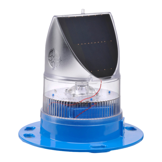
3.0 AV-70 Models (ICAO, FAA L-861T and L-863) The AV-70 solar airfield light is designed to comply with ICAO, FAA 861T and 863 requirements and is exceptional in its ability to operate reliably in low sunlight conditions. Made from tough, durable polycarbonate and using the latest LED’s, the AV-70 light boasts dual high-performance solar modules incorporated into Avlite’s proprietary optics. - Page 7 (Behind) Optional User replaceable External Switch battery in sealed compartment Diam 17 mm / 0.67 in x 30 mm / 1.18 in Slot 6 Places Flash Adjustment Sealed Vent 231 mm 9.09 in Want the latest product information? Visit www.avlite.com...
-
Page 8: Data Sheet
EN61000-6-4:2012, EN61000-6-2:2019 Quality Assurance ISO9001:2015 Waterproof IP68 Trademarks AVLITE® and AV-HMALS® is a registered trademark of Avlite Systems Other Warranty * 3 year warranty Options Available Handheld RF Controller, IR LEDs, External Switch, Pilot Activated Lighting Control (PALC) Terms and Conditions Please refer to the light installation manual for furtherspecifications. -
Page 9: Safety Information
Do not stare at the LED or shine the LED into your eyes or those of another person. • Dispose of the product according to the local laws and regulations for your region, for example, at a recycling centre that accepts electronic devices. Want the latest product information? Visit www.avlite.com... -
Page 10: Operation And Setup
240VAC utility if available. The AV-70 fixtures will charge automatically when placed in sunlight. In addition, the AV-70 is also fitted with an external interface port on the base of the unit that can be used to manually charge the battery. -
Page 11: Lantern Operation
4. Set the Flash Code - For non-compliant, non-RF variants, the flash code can be adjusted via the rotary switches on the AV-70 PCB (see '6.3 Rotary Switches A and B' section of this manual). For RF enabled variants, the flash code is set by the factory and does not require further adjustment. -
Page 12: Rotary Switches A And B
6.3 Rotary switches A and B All AV-70 fixtures have 2 rotary switches marked A and B on the flasher unit (see image on previous page). These are used differently for RF and non-RF variants. These are described below: RF Variants: For RF variants, rotary switches A and B are used to define the light group and node assignment for a particular light in the system. - Page 13 1 FL 5 S 4 LFL 15 S 11.0 1 FL 5 S 4 OC 15 S 5 FL 5 S 6 LFL 20 S 18.0 1 FL 5 S 4 FL 26 S 25.0 Want the latest product information? Visit www.avlite.com...
- Page 14 E FL (4) 16 S D FL (4) 20 S D FL (4) 20 S 13.5 D FL (4) 20 S 10.5 F FL (4) 20 S F Q (4) 20 S 16.5 E Q (4) 28 S 24.5 Solar Aviation Light AV-70...
- Page 15 MO (A) 10 S MO (D) 10 S MO (A) 15 S 11.0 MO (U) 15 S 11.8 MO (U) 15 S 10.7 MO (U) 15 S 10.1 MO (B) 15 S 10.5 Want the latest product information? Visit www.avlite.com...
-
Page 16: Optional Ir Remote
In Always On mode, the daylight sensor is disabled and the lantern will remain ON. In Standby mode, the lantern is turned off and the daylight sensor is disabled. In Dusk-to-Dawn, the daylight sensor is enabled. Read Operation mode Always on mode Standby mode Dusk-to-Dawn mode Solar Aviation Light AV-70... - Page 17 Example key sequence: (Set the intensity level to 5 – undefined.) The light flashes 5 times for 1 second. When a key sequence has been entered successfully the light will respond acknowledgement with a 1 second flash. Want the latest product information? Visit www.avlite.com...
-
Page 18: Unpacking, Installation, Wiring And Setup
8.0 Unpacking, Installation, Wiring and Setup 8.1 Unpacking Unpack all hardware and inspect for damage. If there is any damage, please contact your Avlite Office. Retain original packing material for possible future use in shipping. 8.2 Installation WARNING: DO NOT connect directly to an unregulated power source. Connecting to an unregu- lated source may result in damage. -
Page 19: Installation Recommendations
Repeat on the other side. For bolts: Fit te AV-70 on the top of the mounting tile. Insert bolts through the holes in the tile, entering from the bottom. Install penny washer and nut on each. Tighten nuts. - Page 20 Ensure that the mounting plate is level using a spirit level. d. Fit the AV-70 mount plate assembly on top of the stake. Using a 6mm Allen key, tighten the bottom socket head cap screw against the stake sleeve.
- Page 21 Fit the frangible sleeve and mounting plate onto the concrete base plate and secure using the M8 x 16 SHCS Level the assembly using a spirit level. d. Fit the AV-70 to the light mounting plate using M8 SHCS, large flat washers and Nylock nuts. For further adjustments on levelling the light, see the next page.
- Page 22 Use longer bolts when required. Important: Please ensure that spacers are not just under one mounting point. Please fill in spacers under other mounting points. Failure to space gaps will result in damage to the base or the mounting plate. Solar Aviation Light AV-70...
-
Page 23: Maintenance And Servicing
Replacing the battery The AV-70 lights are the only compact aviation light with a double sealed battery compartment. This provides the user with the ability to change the battery after years of operation. - Page 24 Long Term Storage Instructions If the AV-70 is to be placed in storage for an extended period, being more than 5 months, please follow the below steps. 1. The 3.6V NiMH Battery must be stored in a fully charged condition.
- Page 25 Safe Battery Handling Charging and Discharging • Always ensure batteries are fully charged when installing new lights. The light will be dispatched from the Avlite factory fully charged. However if time has elapsed between dispatch and installation, battery voltage must be checked.
-
Page 26: Troubleshooting
Ensure the light is not set to ALWAYS ON Light will not respond to control- Refer to AvMesh RF Communications System Installation ler in Radio Control Mode and Trouble Shooting Manual, available under the AV-70 Downloads section. 11.0 Warranty Refer to Avlite website at www.Avlite.com. -
Page 27: Notes
Notes Want the latest product information? Visit www.avlite.com... - Page 28 Contact Us! Avlite's solutions are easy-to-install and scalable. We have a solution for every budget. Avlite Head Office Avlite USA 11 Industrial Drive, Somerville 61 Business Park Drive, Tilton Victoria, Australia 3912 New Hampshire, USA 03276 T: +61 (0)3 5977 6128...
Need help?
Do you have a question about the AV-70 and is the answer not in the manual?
Questions and answers