Table of Contents
Advertisement
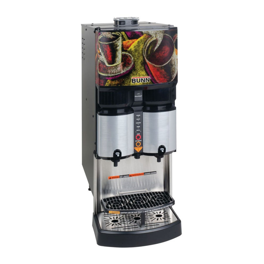
BUNN
INSTALLATION & OPERATING MANUAL
34766.0000
12/02 ©2002 Bunn-O-Matic Corporation
BUNN-O-MATIC CORPORATION
POST OFFICE BOX 3227
SPRINGFIELD, ILLINOIS 62708-3227
PHONE: (217) 529-6601 FAX: (217) 529-6644
®
R
W E
P O
Y
A D
R E
N
IO
R T
P O
S E
R IN
L
F IL
R E
!
O P
S T
R
T E
W A
T
H O
D S
A U
C H
E S
U I D
L I Q
N T
M E
S E
T I S
E R
A V
!
I D S
I Q U
T L
H O
G
N I N
A R
! W
LCA-2
LCC-2
www.bunnomatic.com
Advertisement
Table of Contents

Related Manuals for Bunn LCA-2 LCC-2


Summary of Contents for Bunn LCA-2 LCC-2
- Page 1 BUNN INSTALLATION & OPERATING MANUAL BUNN-O-MATIC CORPORATION 34766.0000 12/02 ©2002 Bunn-O-Matic Corporation ® U I D L I Q T I S I D S I Q U N I N POST OFFICE BOX 3227 SPRINGFIELD, ILLINOIS 62708-3227 PHONE: (217) 529-6601 FAX: (217) 529-6644...
-
Page 2: Table Of Contents
REPAIR, REPLACEMENT OR REFUND. In no event shall BUNN be liable for any other damage or loss, including, but not limited to, lost profits, lost sales, loss of use of equipment, claims of Buyer’s customers, cost of capital, cost of down time, cost of substitute equipment, facilities or services, or any other special, incidental or consequential damages. -
Page 3: Introduction
KEEP COMBUSTIBLES AWAY. FAILURE TO COMPLY RISKS EQUIPMENT DAMAGE, FIRE OR SHOCK HAZARD. READ THE ENTIRE OPERATING MANUAL BEFORE USING THIS PRODUCT 00986.0002E 5/98 ©1994 Bunn-O-Matic Corporation 00986.0002 WARNING HAZARDOUS VOLTAGE U N P L U G B R E W E R B E F O R E R E M O V I N G ! 12652.0000... -
Page 4: Electrical Requirements
It can be purchased direct from Bunn-O-Matic (part number 00326.0000). Bunn-O-Matic does not recommend the use of a saddle valve to install the dispenser. The size and shape of the hole made in the supply line by this type of device may restrict water flow. -
Page 5: Initial Set-Up
NOTE: The LCC-2 (Chilled Unit) weighs approximately 80 lbs. (36.3 kg) and the LCA-2 (Ambient Unit) weighs approximately 70 lbs. (31.8 kg). If necessary, use more than one person when lifting or moving the dispenser. 1. Locate and remove the information packets and tube kits from top of packaging and set aside. 2. -
Page 6: Setting Dispenser Flow Rate
The dispenser comes from the factory with flow restrictors in the mix chambers. With the restrictors in place the dispense rate is about 1.8 oz./sec (53.2 ml/sec) and is used primarily for cup at a time dispensing. The flow restrictors can be removed to increase the dispense rate to about 2.5 oz./sec (74 ml/sec) for larger volume dispensing (airpots, carafes, etc.). -
Page 7: Selecting The Correct Pump Tubing
2. Depress the tension screw and remove it from the notch in the pump body, releasing the spring tension on the pump band. 3. Apply lubricant (BUNN-O-MATIC part number M2548.1000) to the new pump tubing. 4. Insert the tubing onto the mix chamber port and wrap the tubing around the pump rotor, making sure that the elbow and clamps end up on the bottom side of the pump body. -
Page 8: Operating Controls & Interface
OPERATING CONTROLS AND INTERFACE 1. Dispense Handles: Pull and Hold to dispense product. 2. Stop Switch: Momentary switch stops all dispense functions. 3. Hot Water Switch: Push and Hold switch to dispense hot water from the center dispense tip. 4. Portion Control Switch: Momentarily pushed by user to activate Portion Control Mode 5. -
Page 9: Initial Fill & Heat
1. Select Normal on the Function Selector Switch and Run on the Mode Selector Switch. 2. Confirm the water supply is on. 3. Connect the dispenser to the power source. The Red POWER LED will illuminate and water will begin flowing into the tank. -
Page 10: Flavorgard™ Feature
FlavorGard™ Feature FlavorGard™ is a patented feed back control loop that monitors the mixed product and adjusts the concentrate delivery rate to maintain a consistent mix profile, i.e. Flavor Profile. The system consists of a conductance probe mounted in the final stages of the mixing chamber, a metering pump with RPM sensor and a digital controller. Once you have completed the installation of the dispenser, entered the desired mix ratio for your concentrate, dispensed several cups of the mixed product, and are satisfied with the Flavor and Strength being delivered, simply enable FlavorGard™, (refer to FlavorGard™... -
Page 11: Rinse Alarm Feature
Periodic rinsing of the mix chambers and dispense tips is essential for proper maintenance and optimum performance of the dispenser. The automated Rinse Alarm feature has three levels of operation, Disabled, Warning Only and Warning with Brew Lockout, see chart for details. Alarm Level Selected Alarm Mode Disabled... -
Page 12: Programming The Dispenser Flow Rate
Remove the lower splash guard assembly to access the digital programming module with LCD display. Press the Down Arrow key to inter the programming menu. Use the Up and Down Arrow keys to scroll through the menu screens. Select Exit to leave the programming function and return to normal operations. NOTE 1: Flashing menu items indicate which selection is active. - Page 13 MENU SCREEN LOCK FLAVOR ? EXIT FLAVORS LOCKED EXIT LF DISP VOLUME Use the (+) or (-) buttons to (-) 0.0oz (+) adjust the volume RT DISP VOLUME Use the (+) or (-) buttons to (-) 0.0oz (+) adjust the volume TANK TEMP 180 Use the (+) or (-) buttons to (-) EXIT (+)
- Page 14 MENU SCREEN SET PASSWORD ? Use the (+) or (-) buttons to change the password. SELECT UNITS Select the preferred units ENG EXIT METRIC CHILLED UNIT ? Select (YES) or (NO) EXIT RINSE ALARM ? Select (YES) or (NO) NO EXIT YES If NO - go to BREW LOCKOUT menu.
- Page 15 MENU SCREEN CAL LF WTR VOL Use the (+) or (-) buttons to 36.0OZ enter volume collected CAL LEFT SIDE ? EXIT YES CAL RIGHT SIDE ? Select (YES) to enable EXIT YES CAL RIGHT PUMP ? Pull the Right dispenser PULL DISPENSER handle CAL RT PUMP VOL...
- Page 16 MENU SCREEN BIB EMPTY -> 400 Use the (+) or (-) buttons to EXIT adjust empty BIB threshold 0 REFILL -> 155 Use the (+) or (-) buttons to (-) EXIT (+) adjust Refill threshold WTR START DELAY Use the (+) or (-) buttons to (-) .15SEC (+) adjust delay time WTR STOP DELAY...
-
Page 17: Loading The Concentrate
LOADING THE CONCENTRATE 1. Thoroughly mix concentrate by vigorously shaking the product Bag-In-Box (BIB). 2. Pull the BIB connector through the hole provided in the box and place it on the drip tray with the connector facing up. (See Fig. 1) 3. -
Page 18: Operating The Dispenser
Set the Function Selector Switch to Normal and the Mode Selector Switch to Run. 1. Pull and Hold Dispense Mode (Cup at a time) a. Place cup on the cup tray beneath the desired dispensing tip. For a large container, flip the cup tray up and place the container on top of the drip tray. -
Page 19: Cleaning And Preventative Maintenance
CLEANING & PREVENTATIVE MAINTENANCE General Cleaning and Sanitizing Procedures Note: The BUNN ® Liquid Coffee Dispenser incorporates a “user selectable” rinse reminder feature, which lights the Rinse LED on the front panel and disables dispensing when it is time to rinse. See Programming Functions to activate this feature. -
Page 20: Replacing The Pump Tubing
How long the tubes last is dependent on usage and properties of the concentrate. Excessive wear will reduce the output of the pumps resulting in a weak mixed beverage. Bunn-O-Matic recommends replacing the Pump Tubing a minimum of once every 6 months or sooner if warranted. -
Page 21: Draining The Hot Water
DRAINING THE HOT WATER TANK CAUTION: The dispenser must be disconnected from the power source throughout these steps. 1. Disconnect the dispenser from the power source. 2. Shut off and disconnect the incoming water supply. 3. Remove the front splash panel. 4. -
Page 22: Troubleshooting
A troubleshooting guide is provided to suggest probable causes and remedies for the most likely problems encountered. If the problem remains after exhausting the troubleshooting steps, contact the Bunn-O-Matic Technical Service Department. • Only qualified service personnel should perform inspection, testing, and repair of electrical equipment. - Page 23 Dispenser Diagnostics Screen Displayed OVERFLOW CUP 1. Refill valve stuck open FULL. EMPTY CUP 2. Faulty refill probe 3. Faulty overflow switch HEATING TIME TOO 1. Tank Heater failure LONG 2. Triac failure CHECK HEATING CIRCUIT 3. Tank Temp. sensor failure FILL TIME TOO LONG 1.
- Page 24 Screen Displayed Possible Cause FINS TEMP SENSOR 1. Corresponding Temperature Sensor OUT OF RANGE Probe wire(s) broken or disconnected. CHECK FOR BAD CONNECTIONS TANK TEMP SENSOR 1. Corresponding Temperature Sensor OUT OF RANGE Probe wire(s) shorted to housing, or to each other.
-
Page 25: Field Calibration Of The Concentrate Pumps
Field Calibration of the Concentrate Pumps / Dispenser Flow Rates The factory set Default Values for the Pump & Dispenser Flow Rates are very accurate and typically do not need to be field calibrated. However, if the mix ratio accuracy is ever in question, this procedure can be used to recalibrate the unit in the field. -
Page 26: Dispenser Flow Rate Calibration
Field Calibration of the Concentrate Pumps / Dispenser Flow Rates Dispenser Flow Rate Calibration 13. Press Down Arrow Key to display the CAL LF WTR FLO menu screen. 14. Place a 64 Oz (2000 ml) graduated container under Left Dispense Tip and Pull the Left Dispense Handle momentarily. -
Page 27: Schematic Wiring Diagram
WHI/BLK J1-16 SELECTOR SWITCH NITE 120 VOLTS AC 2 WIRE 120/208-240 VOLTS AC 3 WIRE 208-240 VOLTS AC 2 WIRE SINGLE PHASE 50/60HZ 34641.0000C 12/02 © 2002 BUNN-O-MATIC CORPORATION SW. & THERMOSTAT TANK HEATER BLU-14 BLK-14 PORTION CONTROL DOOR WHI/BLU... - Page 28 RT DISP. SW. J1-10 GRN/BLK WHI/BLK J1-16 SELECTOR SWITCH NITE 230 VOLTS AC 2 WIRE SINGLE PHASE 50 HZ 34641.0001B 12/02 © 2002 BUNN-O-MATIC CORPORATION RFI SUPPRESION CAPACITOR LIMIT THERMOSTAT SW. & THERMOSTAT TANK HEATER BLU-14 BLK-14 RED-14 PORTION CONTROL DOOR...
Need help?
Do you have a question about the LCA-2 LCC-2 and is the answer not in the manual?
Questions and answers