Table of Contents
Advertisement
Quick Links
Advertisement
Table of Contents

Related Manuals for Miller Big Blue Turbo


Summary of Contents for Miller Big Blue Turbo
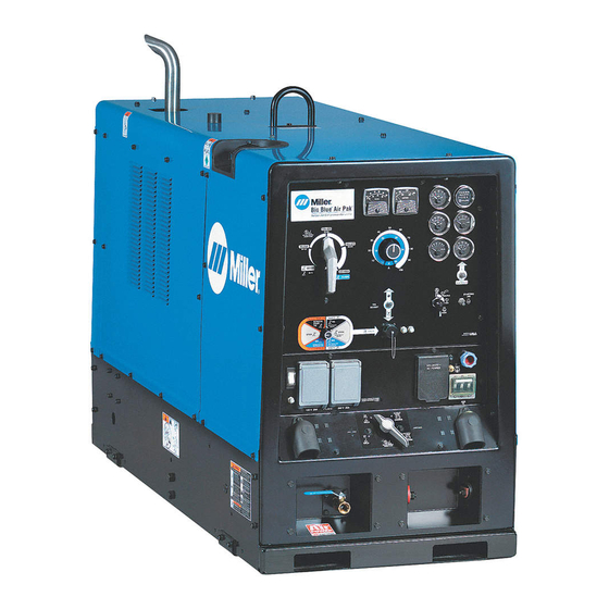
- Page 1 212 049M 2006−12 Processes Stick (SMAW) Welding MIG (GMAW) Welding Flux Cored (FCAW) Welding TIG (GTAW) Welding Air Carbon Arc (CAC-A) Cutting and Gouging Description Engine Driven Welding Generator Big Blue Turbo ® File: Engine Drive Visit our website at www.MillerWelds.com...
- Page 2 We know you don’t have time to do it any other way. That’s why when Niels Miller first started building arc welders in 1929, he made sure his products offered long-lasting value and superior quality.
-
Page 3: Table Of Contents
TABLE OF CONTENTS SECTION 1 − SAFETY PRECAUTIONS − READ BEFORE USING ........1-1. - Page 4 TABLE OF CONTENTS 8-3. Servicing Air Cleaner ..............8-4.
-
Page 5: Section 1 − Safety Precautions − Read Before Using
SECTION 1 − SAFETY PRECAUTIONS − READ BEFORE USING rom _nd_3/05 Y Warning: Protect yourself and others from injury — read and follow these precautions. 1-1. Symbol Usage Means Warning! Watch Out! There are possible hazards with this procedure! The possible hazards are shown in the adjoining symbols. -
Page 6: Engine Hazards
WELDING can cause fire or explosion. HOT PARTS can cause severe burns. D Do not touch hot parts bare handed. Welding on closed containers, such as tanks, drums, or D Allow cooling period before working on equipment. pipes, can cause them to blow up. Sparks can fly off from the welding arc. -
Page 7: Compressed Air Hazards
D Use only genuine Miller/Hobart replacement parts. 1-5. Additional Symbols For Installation, Operation, And Maintenance FALLING UNIT can cause injury. OVERUSE can cause OVERHEATING. -
Page 8: California Proposition 65 Warnings
READ INSTRUCTIONS. ARC WELDING can cause interference. D Use only genuine MILLER/Hobart replacement D Electromagnetic energy can interfere with sensitive parts. electronic equipment such as microprocessors, computers, and computer-driven equipment such as D Perform engine and air compressor (if applicable) robots. -
Page 9: Section 2 − Consignes De Sécurité − Lire Avant Utilisation
SECTION 2 − CONSIGNES DE SÉCURITÉ − LIRE AVANT UTILISATION rom_fre 3/05 Avertissement: Protégez vous et les autres des blessures − lisez et suivez ces précautions. 2-1. Signification des symboles Signifie Mise en garde ! Soyez vigilant ! Cette procédure Ce groupe de symboles signi- présente des risques de danger ! Ceux-ci sont identifiés fie Mise en garde ! Soyez vigi-... -
Page 10: Dangers Existant En Relation Avec Le Moteur
LE SOUDAGE peut provoquer un in- DES PIÈCES CHAUDES peuvent cendie ou une explosion. provoquer des brûlures graves. D Ne pas toucher à mains nues les parties chaudes. Le soudage effectué sur des conteneurs fermés tels que des D Prévoir une période de refroidissement avant de travailler à réservoirs, tambours ou des conduites peut provoquer leur l’équipement. -
Page 11: Dangers Liés À L'air Comprimé
éléments ou avant d’ouvrir la fectuer la maintenance. purge ou le bouchon de remplissage d’huile. D Utiliser uniquement des pièces de rechange Miller/Hobart. 2-5. Dangers supplémentaires en relation avec l’installation, le fonctionnement et la maintenance L’EMPLOI EXCESSIF peut... -
Page 12: Proposition Californienne 65 Avertissements
LIRE LES INSTRUCTIONS. LE SOUDAGE À L’ARC risque de provoquer des interférences. D Utiliser seulement les pièces de rechange d’origine. D Effectuer la maintenance du moteur et du compresseur D L’énergie électromagnétique risque de provoquer des in- (si applicable) suivant ce manuel et le manuel du moteur/ terférences pour l’équipement électronique sensible tel compresseur (si applicable). -
Page 13: Section 3 − Definitions
SECTION 3 − DEFINITIONS 3-1. Symbols And Definitions Fast (Run, Weld/ Stop Engine Slow (Idle) Start Engine Power) Check engine belt Check Air Cleaner Starting Aid Engine Battery (Engine) Hourmeter (HM) Temperature Circuit Protector Do Not Switch Read Operator’s Certified/Trained Engine Oil Under Load Manual... -
Page 14: Section 4 − Specifications
SECTION 4 − SPECIFICATIONS 4-1. Weld, Power, And Engine Specifications Maximum Weld Rated Engine Welding Open-Circuit Generator Power Fuel Tank Output Welding Engine Mode Voltage Rating Capacity Range Output Capacity (Nominal) 600 A, 44 Volts CC/DC 20 − 750 A 100% Duty Standard DEUTZ... -
Page 15: Stick And Mig Volt-Ampere Curves
4-4. Stick And MIG Volt-Ampere Curves The volt-ampere curve shows the minimum and maximum voltage and amperage output capabilities of the welding generator. Curves of all A. DC Stick Mode other settings fall between the curves shown. Ranges 300 − Max 185 −... -
Page 16: Dc Tig Volt-Ampere Curves
4-5. DC TIG Volt-Ampere Curves The volt-ampere curve shows the minimum and maximum voltage and amperage output capabilities of the welding generator. Curves of all other settings fall between the curves shown. Ranges 60−450 40−330 30−220 20−110 50 100 150 200 250 300 350 400 450 500 550 600 650 700 DC AMPERES 208 136 4-6. -
Page 17: Duty Cycle And Overheating
4-7. Duty Cycle And Overheating 100% Duty Cycle At 600 Amperes Duty Cycle is percentage of 10 min- utes that unit can weld at rated load without overheating. Y Exceeding duty cycle can damage unit void warranty. Continuous Welding 1000 80 100 % DUTY CYCLE 212 060-C... -
Page 18: Manufacturing Rating Label
4-9. Manufacturing Rating Label OM-4420 Page 14... -
Page 19: Section 5 − Installation
SECTION 5 − INSTALLATION 5-1. Installing Welding Generator Y Always securely fasten weld- ing generator onto transport vehicle or trailer and comply with all DOT and other applica- Movement ble codes. Y Always ground generator frame to vehicle frame to pre- vent electric shock and static electricity hazards. -
Page 20: Mounting Welding Generator
5-2. Mounting Welding Generator Y Do not weld on base. Weld- ing on base can cause fuel tank fire or explosion. Weld only on the four mounting brackets or bolt unit down. Supporting The Unit Y Do not mount unit by sup- porting the base only at the four mounting brackets. -
Page 21: Installing Optional Spark Arrestor Muffler
5-3. Installing Optional Spark Arrestor Muffler Y Stop engine and let cool. Spark Arrestor Muffler Double-Flanged Elbow Flat Washer Mount Bracket Screw Single-Flanged Elbow Rain Cap 10 Clamp Loosely assemble components as shown. Mount the muffler with the clean- out plug to the outside. After assembly, final-tighten all clamps and hardware. -
Page 22: Activating The Dry Charge Battery (If Applicable)
5-4. Activating The Dry Charge Battery (If Applicable) Y Always wear a face shield, rubber gloves and protective clothing when working on a battery. Remove battery from unit. 11 Vent Caps 12 Sulfuric Acid Electrolyte (1.265 Specific Gravity) 13 Well Fill each cell with electrolyte to bottom of well (maximum). -
Page 23: Using The Optional Battery Disconnect Switch
5-6. Using The Optional Battery Disconnect Switch Y Stop engine. Battery Disconnect Switch The battery disconnect switch dis- connects battery voltage from the circuit. When the switch is turned Off, the front panel controls do not work. To run unit, turn switch to On posi- tion. -
Page 24: Engine Prestart Checks
5-7. Engine Prestart Checks Engine Oil Full Diesel Full 803 454 Fuel add oil (see maintenance label for engine oil Check all engine fluids daily. specifications). Y Do not use gasoline. Gasoline will Engine must be cold and on a level surface. damage engine. -
Page 25: Connecting To Weld Output Terminals
5-8. Connecting To Weld Output Terminals Stick And TIG Welding MIG And FCAW Welding For Stick welding Direct Current Electrode For MIG welding Direct Current Electrode Positive (DCEP), connect electrode hold- Positive (DCEP), connect wire feeder er cable to Positive (+) terminal on left and cable to Positive (+) terminal on left and work cable to Negative (−) terminal on work cable to Negative (−) terminal on... -
Page 26: Selecting Weld Cable Sizes
5-9. Selecting Weld Cable Sizes* Weld Cable Size** and Total Cable (Copper) Length in Weld Circuit Not Exceeding*** 150 ft 200 ft 250 ft 300 ft 350 ft 400 ft 100 ft (30 m) or Less (45 m) (60 m) (70 m) (90 m) (105 m) -
Page 27: Connecting To Remote 14 Receptacle Rc14
5-10. Connecting To Remote 14 Receptacle RC14 Socket* Socket Information 24 volts ac. Protected by sup- plementary protector CB5 (see Section 8-8). 24 VOLTS AC Contact closure to A completes 24 volt ac contactor control circuit. Output to remote control:+10 volts dc in MIG or Stick mode;... -
Page 28: Section 6 − Operating The Welding Generator
SECTION 6 − OPERATING THE WELDING GENERATOR 6-1. Controls (See Section 6-2) 803 454 / 217 638-A OM-4420 Page 24... -
Page 29: Description Of Controls (See Section 6-1)
6-2. Description Of Controls (See Section 6-1) Engine Starting Controls scheduling maintenance. Use the highest range for MIG welding and for cutting and gouging (CAC-A). Starting Aid Switch Fuel Gauge For most welding applications, use lowest Use switch to energize starting aid for cold Use gauge to check fuel level. -
Page 30: Process/Contactor Switch
6-3. Process/Contactor Switch Process/Contactor Switch Y Weld output terminals are ener- gized when Process/Contactor switch is in a Weld Terminals Al- ways On position and the en- gine is running. Y DC voltage is still present at the weld terminals when Process/ Contactor switch is in the Re- mote On/Off Switch Required −... -
Page 31: Using Remote Voltage/Amperage Control
6-4. Using Remote Voltage/Amperage Control Remote 14 Receptacle RC14 Connect optional remote control to RC14 (see Section 5-10). 803 454 In Example: Example: Combination Remote Amperage Control (Stick) Process = Stick (Using Remote On/Off) Range = 125 to 400 A DC Min = 125 A DC Max = 400 A DC Max (400 A DC) -
Page 32: Section 7 − Operating Auxiliary Equipment
SECTION 7 − OPERATING AUXILIARY EQUIPMENT 7-1. 120 Volt And 240 Volt Receptacles 120 V 20 A AC GFCI Receptacle GFCI1 240 V 30 A AC Twistlock Receptacle RC1 Receptacles supply 60 Hz single- phase power at weld/power speed. If a ground fault is detected, GFCI Reset button pops... -
Page 33: Optional Generator Power Receptacles
7-2. Optional Generator Power Receptacles 120 V 20 A AC GFCI Receptacle GFCI1 240 V 16 A AC European Receptacle RC1 European Receptacle 240 V 15 A AC Australian Receptacle RC1 240 V 15 A AC South African Receptacle RC1 Receptacles supply 60 Hz single- phase power at weld/power speed. -
Page 34: Section 8 − Engine/Generator Maintenance
SECTION 8 − ENGINE/GENERATOR MAINTENANCE 8-1. Routine Maintenance Y Stop engine before maintaining. See Engine Manual and Maintenance Label Recycle engine for important start-up, service, and storage fluids. information. Service engine more often if used in severe conditions. n = Check Z = Change ~ = Clean l = Replace... -
Page 35: Engine Maintenance Label
8-2. Engine Maintenance Label OM-4420 Page 31... -
Page 36: Servicing Air Cleaner
8-3. Servicing Air Cleaner Y Stop engine. Y Do not run engine without air cleaner or with dirty element. En- gine damage caused by using a damaged element is not covered by the warranty. Engine Air Cleaner The air cleaner primary element can be cleaned but the dirt holding capac- ity of the filter is reduced with each cleaning. -
Page 37: Inspecting/Cleaning Optional Spark Arrestor Muffler
8-4. Inspecting/Cleaning Optional Spark Arrestor Muffler Y Stop engine and let cool. Spark Arrestor Muffler Cleanout Plug Remove plug and remove any dirt covering cleanout hole. Start engine and run at idle speed to blow out cleanout hole. If nothing blows out of hole, briefly cover end of exhaust pipe with fireproof material. -
Page 38: Adjusting Engine Speed
8-6. Adjusting Engine Speed Y Stop engine and let cool. Engine speed is factory set and should not require adjustment. Af- ter tuning engine, check engine no load speed with a tachometer or fre- quency meter (see table for no load speeds). -
Page 39: Servicing Engine Fuel And Lubrication Systems
8-7. Servicing Engine Fuel And Lubrication Systems Tools Needed: 803 454 Y Stop engine and let cool. base. See engine manual and engine main- To replace secondary fuel filter: tenance label for oil specifications. See engine manual. Y After servicing, start engine and To drain water from fuel system: check for fuel leaks. -
Page 40: Engine/Generator Overload Protection
8-8. Engine/Generator Overload Protection Y Stop engine. When a supplementary protector, circuit breaker or fuse opens, it usually indicates a more serious problem exists. Contact Factory Authorized Service Agent. Fuse F1 Fuse F2 F1 and F2 protect the stator exciter winding from overload. -
Page 41: Section 9 − Troubleshooting
SECTION 9 − TROUBLESHOOTING 9-1. Troubleshooting Tables A. Welding Trouble Remedy No weld output; generator power output Place Process/Contactor switch in a Weld Terminals Always On position, or place switch in a Remote okay at ac receptacles. position and connect remote contactor to Remote 14 receptacle RC14 (see Sections 5-10 and 6-1). Check position of Ampere Range switch. - Page 42 Trouble Remedy No remote fine amperage or voltage Place Panel/Remote switch in Remote position. control. Check and secure connections to Remote 14 receptacle RC14 (see Section 5-10). Repair or replace remote control device. Have Factory Authorized Service Agent check PC1 current sensing leads (36 and 37), and connections. Constant speed wire feeder does not Reset supplementary protector(s) CB5 and CB13 (see Section 8-8).
- Page 43 Trouble Remedy Engine cranks but does not start. Check fuel level. Optional low fuel shutdown stops engine if fuel level is low. Reset supplementary protector CB13 (see Section 8-8). Have Factory Authorized Service Agent check engine wiring harness and components. Check battery and replace if necessary.
-
Page 44: Section 10 − Electrical Diagram
SECTION 10 − ELECTRICAL DIAGRAM Figure 10-1. Circuit Diagram For Welding Generator OM-4420 Page 40... - Page 45 217 852-D OM-4420 Page 41...
-
Page 46: Section 11 − Run-In Procedure
SECTION 11 − RUN-IN PROCEDURE run_in1 11/05 11-1. Wetstacking Y Do perform run-in procedure at less than 20 volts weld output and do not exceed duty cycle or equip- ment damage may occur. Welding Generator Run diesel engines near rated volt- age and current during run-in period to properly seat piston rings and prevent wetstacking. -
Page 47: Run-In Procedure Using Load Bank
11-2. Run-In Procedure Using Load Bank Y Stop engine. Y Do not touch hot exhaust pipe, engine parts, or load bank/grid. Y Keep exhaust and pipe away from flammables. Y Do perform run-in procedure at less than 20 volts weld output and do not exceed duty cycle or equip- ment damage may occur. -
Page 48: Run-In Procedure Using Resistance Grid
11-3. Run-In Procedure Using Resistance Grid Y Stop engine. Y Do not touch hot exhaust pipe, engine parts, or load bank/grid. Y Keep exhaust and pipe away from flammables. Y Do perform run-in procedure at less than 20 volts weld output and do not exceed duty cycle or equip- ment damage may occur. -
Page 49: Section 12 − Generator Power Guidelines
SECTION 12 − GENERATOR POWER GUIDELINES NOTE The views in this section are intended to be representative of all engine-driven welding generators. Your unit may differ from those shown. 12-1. Selecting Equipment Generator Power Receptacles − Neutral Bonded To Frame 3-Prong Plug From Case Grounded Equipment 2-Prong Plug From Double... - Page 50 12-3. Grounding When Supplying Building Systems Equipment Grounding Terminal Grounding Cable GND/PE Use #10 AWG or larger insulated copper wire. Ground Device Y Ground generator to system earth ground if supplying power to a premises (home, shop, farm) wiring system. Use ground device as stated in electrical codes.
- Page 51 12-5. Approximate Power Requirements For Industrial Motors Industrial Motors Rating Starting Watts Running Watts Split Phase 1/8 HP 1/6 HP 1225 1/4 HP 1600 1/3 HP 2100 1/2 HP 3175 Capacitor Start-Induction Run 1/3 HP 2020 1/2 HP 3075 3/4 HP 4500 1400 1 HP...
- Page 52 12-7. Approximate Power Requirements For Contractor Equipment Contractor Rating Starting Watts Running Watts Hand Drill 1/4 in 3/8 in 1/2 in Circular Saw 6-1/2 in 7-1/4 in 8-1/4 in 1400 1400 Table Saw 9 in 4500 1500 10 in 6300 1800 Band Saw 14 in...
- Page 53 12-8. Power Required To Start Motor Motor Start Code AC MOTOR Running Amperage VOLTS AMPS Motor HP CODE Motor Voltage PHASE To find starting amperage: Step 1: Find code and use table to find kVA/HP. If code is not listed, multiply running amperage by six to find starting amperage.
- Page 54 12-10. Typical Connections To Supply Standby Power Y Properly install and ground this equipment according to its Owner’s Manual and national, state, and local codes. Fused Utility Welding Disconnect Electrical Generator Transfer Switch Switch Service Output (If Required) Essential Loads Y Have only qualified persons perform Switch transfers the electrical load from Connect generator with temporary or perma-...
- Page 55 12-11. Selecting Extension Cord (Use Shortest Cord Possible) Cord Lengths for 120 Volt Loads Y If unit does not have GFCI receptacles, use GFCI-protected extension cord. Maximum Allowable Cord Length in ft (m) for Conductor Size (AWG)* Current Load (Watts) (Amperes) 350 (106) 225 (68)
-
Page 56: Section 13 − Selecting And Preparing A Tungsten For Dc Or Ac Welding
SECTION 13 − SELECTING AND PREPARING A TUNGSTEN FOR DC OR AC WELDING gtaw_Phase_7/2006 Y Whenever possible and practical, use DC weld output instead of AC weld output. 13-1. Selecting Tungsten Electrode ( Wear Clean gloves To Prevent Contamination Of Tungsten ♦... -
Page 57: Section 14 − Guidelines For Tig Welding (Gtaw)
SECTION 14 − GUIDELINES FOR TIG WELDING (GTAW) gtaw 7/2006 14-1. Positioning The Torch Y Grinding the tungsten elec- trode produces dust and fly- ing sparks which can cause injury and start fires. Use lo- cal exhaust (forced ventila- tion) at the grinder or wear an approved respirator. -
Page 58: Torch Movement During Welding
14-2. Torch Movement During Welding Tungsten Without Filler Rod ° Welding direction Form pool Tilt torch Move torch to front of pool. Repeat process. Tungsten With Filler Rod ° ° Welding direction Form pool Tilt torch Add filler metal Remove rod Move torch to front of pool. -
Page 59: Positioning Torch Tungsten For Various Weld Joints
14-3. Positioning Torch Tungsten For Various Weld Joints ° Butt Weld And Stringer Bead ° ° ° “T” Joint ° ° ° ° Lap Joint ° ° ° ° Corner Joint ° ° ST-162 003 / S-0792 OM-4420 Page 55... -
Page 60: Section 15 − Parts List
SECTION 15 − PARTS LIST Hardware is common and not available unless listed. 119 − Figure 15-5 111 − Figure 15-2 117 − Figure 15-3 Figure 15-1. Main Assembly OM-4420 Page 56... - Page 61 93 − Figure 15-4 78 79 803 455 OM-4420 Page 57...
- Page 62 Item Dia. Part Mkgs. Description Quantity Figure 15-1. Main Assembly ....189824 Panel, Gen LH ...........
- Page 63 Item Dia. Part Mkgs. Description Quantity Figure 15-1. Main Assembly (Continued) ....218619 Engine, Deutz Dsl Elec Bf4m2011 (includes) ......
- Page 64 Item Dia. Part Mkgs. Description Quantity Figure 15-1. Main Assembly (Continued) ....174064 Idle, Solenoid Assy (includes) ........
- Page 65 Item Dia. Part Mkgs. Description Quantity Figure 15-1. Main Assembly (Continued) ....049525 Nut, 312−18 U−nut Multi−thread ........
- Page 66 803 456-A Figure 15-2. Control Box Assembly OM-4420 Page 62...
- Page 67 Item Dia. Part Mkgs. Description Quantity Figure 15-2. Control Box Assembly − (Figure 15-1 Item 111) ..F1, F2 . . . 085874 Fuse, Mintr Cer Slo−blo 10. Amp 250 Volt ......
- Page 68 Hardware is common and not available unless listed. 803 457 Figure 15-3. Panel, Front w/Components Item Dia. Part Mkgs. Description Quantity Figure 15-3. Panel, Front w/Components (Figure 15-1 Item 117) ....217638 Plate, Screened Ident Control (Order By Model And Serial Number) .
- Page 69 Item Dia. Part Mkgs. Description Quantity Figure 15-3. Panel, Front w/Components (Continued) ....192558 Harness, Range Switch (includes) ........
- Page 70 Item Dia. Part Mkgs. Description Quantity Figure 15-3. Panel, Front w/Components (Continued) ....097924 Knob, Pointer 1.625 Dia X .250 Id W/Set Screwsplstc ....
- Page 71 Item Dia. Part Mkgs. Description Quantity Figure 15-4. Generator (Figure 15-1 Item 93) ....132053 Screw, 375−16x1.50 Hex Hd−pln Gr5 Pld ......
- Page 72 Hardware is common and not available unless listed. 802 279-A Figure 15-5. Main Rectifier Assembly Item Dia. Part Mkgs. Description Quantity Figure 15-5. Main Rectifier Assembly (Figure 15-1 Item 119) ...
- Page 73 Notes MATERIAL THICKNESS REFERENCE CHART 24 Gauge (.025 in) 22 Gauge (.031 in) 20 Gauge (.037 in) 18 Gauge (.050 in) 16 Gauge (.063 in) 14 Gauge (.078 in) 1/8 in (.125 in) 3/16 in (.188 in) 1/4 in (.25 in) 5/16 in (.313 in) 3/8 in (.375 in) 1/2 in (.5 in)
- Page 75 Effective January 1, 2006 (Equipment with a serial number preface of “LG” or newer) This limited warranty supersedes all previous Miller warranties and is exclusive with no other Warranty Questions? guarantees or warranties expressed or implied. LIMITED WARRANTY − Subject to the terms and conditions...
- Page 76 Contact the Delivering Carrier to: File a claim for loss or damage during shipment. For assistance in filing or settling claims, contact your distributor and/or equipment manufacturer’s Transportation Department. © PRINTED IN USA 2006 Miller Electric Mfg. Co. 2006−01...
Need help?
Do you have a question about the Big Blue Turbo and is the answer not in the manual?
Questions and answers