Table of Contents
Advertisement
Advertisement
Table of Contents
Troubleshooting

Related Manuals for Sizewise Bari Rehab Platform 3


Summary of Contents for Sizewise Bari Rehab Platform 3
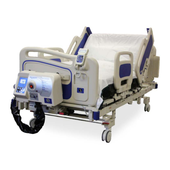
- Page 1 User Manual Bari Rehab Platform 3™ 8113 Rev. 2.0 2/26/2021 ...
-
Page 2: Declaration Of Conformity
Declaration of Conformity... -
Page 3: Table Of Contents
General Warnings and Safety Instructions ................. 8 Device Information ......................... 9 Description of the Bari Rehab Platform 3™ ................9 Bari Rehab Platform 3™ Specifications ................... 10 Description of the SW Rest Secure System™ (RSS) ............... 12 ... - Page 4 Bed Operating Instructions ....................... 22 Hand Control ......................... 22 RSS Operating Instructions....................... 23 Hand Control ......................... 23 Basic Set-Up ......................... 24 Bed Exit Alarm ........................24 Scale System: Zeroing the Scale ................... 25 Scale System: Adding/Removing Items ................
- Page 5 Fasteners ........................... 64 Storage and Disposal......................... 64 Troubleshooting ..........................65 Bari Rehab Platform 3™ Troubleshooting ................65 SW Rest Secure System™ Troubleshooting ................66 Power Drive Troubleshooting ....................67 Touchpad Flash Codes ......................67 ...
-
Page 6: Definitions And Symbols
Definitions and Symbols Definitions Throughout this manual different type fonts and symbols are used to aid user readability and understanding of the content. Below are some examples. Standard Text Used for regular information. Bold Face Text Emphasizes a word or phrase. NOTE SETS APART SPECIAL INFORMATION OR IMPORTANT INSTRUCTION CLARIFICATION. - Page 7 Symbol for Type B applied parts indicating protection provided against electrical shock. The pinch point is spacing between movable parts of the device which, in positions of normal use fail to maintain a clearance of ≤ 8mm (0.315”) or ≥ 25mm (0.984”). Protective Earth Terminal Grounding symbol.
-
Page 8: General Warnings And Safety Instructions
For user and patient safety, read and follow all warnings and instructions that apply to use of the Bari Rehab Platform 3™. Before using this bed, the user must know what to do to ensure safety. Put the patient at ease. The care provider should communicate with the patient by telling them what they are planning to do. -
Page 9: Device Information
Device Information Description of the Bari Rehab Platform 3™ The Bari Rehab Platform 3™ is an electric bed. Its purpose is to support patients who have problems requiring specialized positioning for their rehabilitation. The positioning nature of this bed also provides care providers convenience in attending to the patients. The frame is constructed entirely from metal and is adjustable in height from a low position of 15.75”... -
Page 10: Bari Rehab Platform 3™ Specifications
Bari Rehab Platform 3™ Specifications Quality Assurance Standards ................IEC 60601 CSA C22.2 No. 601.1 IEC/EN 60601-2-52 IEC/EN 60601-1 IEC 60601-1-2 Degree of Protection Against Electric Shock ............Type B Degree of Protection Against Ingress of Water ............IPX4 Electrical Rating ............115VAC 60Hz, 7.6 amps (US model) 230VAC 50/60Hz, 7.6 amps (non-US models) - Page 11 Safe Working Load – Bed ................ 1000 lbs. / 453 kg. Optional IV Pole ..............50 lbs. / 22 kg. Optional Trapeze ............850 lbs. / 385 kg. (Exceeding these limits will void the warranty) WARNING: Exceeding the weight capacity and/or safe working load listed in the specifications could result in patient or user injury as well as damage to equipment or other property.
-
Page 12: Description Of The Sw Rest Secure System™ (Rss)
Description of the SW Rest Secure System™ (RSS) The purpose of the SW Rest Secure System™ (RSS) is to alert the care provider that a patient is attempting to exit the bed or is in an immediate risk of falling in settings where continuous surveillance of a patient is not possible. -
Page 13: Sw Rest Secure System™ Specifications
SW Rest Secure System™ Specifications RSS Control Module The RSS Control Module is located under the bed. Housing Material ....................ABS, UL94-V0 rated Width......................7.25” / 18.5 cm Length ......................3.25” / 8.5 cm Thickness ......................2.00” / 5 cm Connectors Power .................... -
Page 14: Rss Hand Control
RSS Hand Control The RSS Hand Control is located on the footboard. Housing Material ....................ABS, UL94-V0 rated Width....................... 3.50” / 8.9 cm Length ......................7.00” / 18 cm Thickness ......................1.75” / 4.5 cm Connectors CAN Network ...................... 6 pin RJ11 Operating Current Normal ........................ -
Page 15: Description Of The Power Drive
Description of the Power Drive The Power Drive 360 is an assistive device for the movement of the bariatric bed easing the transport of patients. The device is battery powered to provide complete flexibility in transport without the constraint of a power cord. The drive wheel is retractable to allow more traditional, manual movement, when desired. -
Page 16: Power Drive Specifications
Power Drive Specifications The Power Drive is located on the patient head center of the bed. Battery Power Type ................. (2) 12V SLA (Sealed Lead Acid) Capacity ........................26 AH Recharge Time ............. (recommended maximum) 12 hours Operating Time ......................2 hours* Operating Current Normal ........................ -
Page 17: Unpacking And Set-Up Instructions
The bolts must be 5/16”-18 x 2 1/2” long Grade 8 Hex Head Cap Screws. There are no exceptions or substitutions to this requirement. Sizewise part number is 27001204. Tools required for assembly: Phillips Screwdriver 3/16”... -
Page 18: Bed Set-Up
Bed Set-Up 1. Position both ends of the bed so that the sections are lined up with each other. 2. Insert a 5/16”-18 x 2 1/2” long Grade 8 bolt (A) in the bottom holes, 2 places. Lift both sections of the bed and insert the brackets (B) on section A, behind the bolts on section B. - Page 19 5. Locate the electrical connectors in the middle of the bed frame and insert them together. 6. Next, plug the small modular connectors into the black box mounted on the center frame. 7. Locate the Electronic Control Module (ECM) at the head end of the bed.
- Page 20 10. Position the bed at least 12” (30.5 cm) from any walls. This will prevent any damage to the walls while the bed is in movement. 11. Lock the casters into their proper position as indicated by the stickers located near the casters on the bed.
-
Page 21: Side Rail Set-Up
Bed rail entrapment is a serious health risk that can result in serious injury or even death. Sizewise recommends the care provider be mindful of the FDA guidelines relevant to bed rail entrapment, as serious injury can result. -
Page 22: Bed Operating Instructions
Bed Operating Instructions Hand Control These instructions are for the general functions of the bed; any special or unique functions will be referenced to in different sections of this manual. Make sure that the bed is correctly positioned and connected to a grounded or hospital grade outlet. WARNING: Once the bed is positioned correctly, lock casters. -
Page 23: Rss Operating Instructions
RSS Operating Instructions Hand Control The hand control has glow-in-the-dark features; in case of power outages operation is not impaired. A. LCD Display – Lighted display shows the weight and allows the navigation of on-screen menus. B. Microphone – Use to record a message for the voice alarm. C. -
Page 24: Basic Set-Up
Basic Set-Up DO NOT use the SW Rest Secure System™ if the power cord is cut, frayed or loosely connected to the bed. Make sure the unit is plugged into AC power and the hand control is connected to the bed’s footboard. -
Page 25: Scale System: Zeroing The Scale
3. Choose one of the four alert types and then press ENTER. The selection has now been made and the user will be returned to the Home Screen. Scale System: Zeroing the Scale With the patient out of the bed, press and hold the ZERO button for 3 seconds. This process sets the tare weight (base weight) and will return to the Home Screen when complete. -
Page 26: Scale System: Weight History Time Setting
Scale System: Weight History Time Setting The SW Rest Secure System™ is designed to record the weight of the patient by date and time. The unit will automatically record the weight for 30 days at a default time of 00:00 hours (midnight). -
Page 27: Protocol Timer: Sound Level Setting
Protocol Timer: Sound Level Setting There are 3 sound levels for the bed exit alarm/protocol reminder. Press the sound level button once for low volume, twice for medium volume, and a third time for high volume. By pressing the sound level button for a fourth time, the sound level will be reset to low volume. - Page 28 6. Using the UP or DOWN arrow the user can set the month and then press ENTER. 7. Using the UP or DOWN arrow the user can set the date and then press ENTER. 8. Using the UP or DOWN arrow the user can now set the year and then press ENTER.
-
Page 29: Bed Exit Alarm: Use Alarm
Bed Exit Alarm: Use Alarm The bed exit alarm function on the SW Rest Secure System™ alerts the care provider that a patient is attempting to exit the bed or is in an immediate risk of falling. This is especially important in settings where continuous surveillance of the patient is not feasible. -
Page 30: Scale System: Use Scale And Access Weight History
Scale System: Use Scale and Access Weight History The SW Rest Secure System’s integrated scale helps reduce the risk of care provider or patient injury by allowing care providers to accurately record the weight of the patient without having to transport or move the patient each time the weight is needed. -
Page 31: Protocol Timer: Using The Timer
Protocol Timer: Using the Timer The SW Rest Secure System™ protocol timer can be utilized to alert the care provider that the patient needs to be attended to or checked on at intervals of 1, 2 or 4 hours. The protocol timer has the capability to alert the care provider by an audible tone on the unit and, if connected to the Nurse Call Interface, can activate the nurse call signal. -
Page 32: Bed Exit Alarm: Record Message
Bed Exit Alarm: Record Message The Bed Exit Menu will allow you to change the alert type, alert tone, and also let you record a message to the patient so they are not startled by the tones of the bed exit alarm. This unit is also equipped with a Nurse Call Interface which will activate the nurse call whether the unit is set to alert tone or voice message. -
Page 33: Scale System: Change Lbs/Kgs Setting
Scale System: Change LBS/KGS Setting This feature will allow the user to display the patient’s weight in either pounds (lbs.) or kilograms (kg.). The default for patient weight display is pounds (lbs.). This unit has a LBS/KGS Lockout feature to prevent an accidental change of units (see the section Rest Secure Operating Instructions section on Scale System: Locking/Unlocking the Unit in LBS/KGS on page 33 for instructions). -
Page 34: Power Drive Operating Instructions
Power Drive Operating Instructions Prior to operating the power drive, read this section and heed any caution statements or warnings. A – Speed Control – Sets the speed of the device. B – Directional Switches – Selects which direction the motor will drive the device. C –... -
Page 35: Additional Driving Instructions
1. The brake pedal must be in the NEUTRAL position or the bed will not steer properly. 2. Turn ON power with the ON/OFF button on the power drive control. When power is activated the drive wheel will drop to the floor. NOTE: The drive will not operate while the charger cord is plugged in. -
Page 36: Proper Use Of The Bed
Proper Use of the Bed WARNING: Follow the instructions for assisting patients in and out of the bed to avoid a fall or injury to the patient and/or care provider. To get in the bed, position the bed at the proper height by following these steps: 1. -
Page 37: Side Rails
Bed rail entrapment is a serious health risk that can result in serious injury or even death. Sizewise recommends the care provider be mindful of the FDA guidelines relevant to bed rail entrapment, as serious injury can result. These guidelines can be found on the FDA website. -
Page 38: Transfers
Transfers WARNING: Follow the instructions for transferring patients to avoid a fall or injury to the patient and/or care provider. Transfers require good balance and agility and are very dangerous. The care provider should learn how to position the body and support himself or herself during a patient transfer. The care provider should work with the patient’s doctor, nurse or therapist to learn safe transfer methods. -
Page 39: Features
Features Casters Head Section Casters At the head section there are lock and steer casters. When locked, the bed can still maneuver but the casters will not swivel, this makes them the steering casters. Press down on the pedal to lock and lift up on the pedal to unlock. -
Page 40: Connection Of Electrical Components
Connection of Electrical Components Should it become necessary to remove any of the cables from the control box, the diagram below will assist in finding the appropriate cables. The diagram also indicates the fuse placement. If needed, replace fuses as marked. A. -
Page 41: Expandable Bed Deck
Expandable Bed Deck To expand or retract the width of the bed, slide the release knob to the unlock position (the release knob is located directly below the label) and slide the deck to the desired width. Be sure the release knob moves back into the lock position. -
Page 42: Power Drive Control
NOT resting on the floor. To raise the wheel, turn off the power drive system. Serial Number Location The bed has a manufacturer serial number, and a Sizewise Rentals LLC serial number. The serial numbers are located at the foot of the bed. -
Page 43: Trapeze Assembly
WARNING: Before positioning patient on bed, verify all components are secure after adjustments, repairs, or servicing of the trapeze, single pole patient assist, or any other overhead components/devices. WARNING: Use only parts, accessories and adapters authorized by Sizewise. Tools required for assembly: 2 - 9/16” wrenches... -
Page 44: Trendelenburg Disabling
1. Attach the end posts into the appropriate brackets on the head and foot sections of the bed. 2. Place the overhead beam into the slots on top of each end post. NOTE: Be sure to place the holes facing upward on the overhead beam. -
Page 45: Seven Zones Of Bed Rail Entrapment
If the patient would have any clinical conditions that could result in risk of falling or improperly lying in bed, the bed should be left at its lowest setting and in flat position when not attended. Sizewise recommends the use of bed rails if they are available. There are seven zones of bed rail entrapment. - Page 46 This bed complies with IEC 60601-2-52 standard for bed rail entrapment. Below are the specifications of that standard. This was taken from the 60601-2-52 standard. DESIGNATOR DESCRIPTION DIMENSION Smallest dimension between elements inside ≤ 120 mm the perimeter of the SIDE RAIL in its raised/locked positions or perimeters created between the SIDE RAIL and fixed parts of the BED.
-
Page 47: Safety Tips
Emissions The Bari Rehab Platform 3™ has been type tested and have passed the requirements of CISPR 11. Observe the following recommendations to minimize radio frequency emissions in this section and the Electromagnetic Interference section. - Page 48 List of Cables and Accessories Replacement parts, such as cables and accessories, must be purchased through Sizewise to ensure proper compliance requirements. WARNING: Using other manufacturer’s cables and accessories may affect EMC performance. Unauthorized use of these items will void warranty and could result in patient and/or user injury as well as damage to equipment or other property.
-
Page 49: Electromagnetic Interference (Emi) From Radio Wave Sources
Electromagnetic Interference (EMI) The Bari Rehab Platform 3™ has been tested and are intended for safe use with other components compliant to IEC 601 standards for medical devices. The Bari Rehab Platform 3™ can cause interference with non-601 regulated equipment and/or other non-601 regulated equipment can cause interference with The Bari Rehab Platform 3™. - Page 50 Table 201 Guidance and Manufacturer’s Declaration – Emissions Equipment and Systems that are NOT Life-Supporting The Bari Rehab Platform 3™ is intended for use in the electromagnetic environment specified below. The customer, or user, of the bed should ensure that it is used in such an environment.
- Page 51 All Equipment and Systems The Bari Rehab Platform 3™ is intended for use in the electromagnetic environment specified below. The customer, or user, of the Bari Rehab Platform 3™ should ensure that it is used in such an environment. Immunity Test...
- Page 52 Table 204 Guidance and Manufacturer’s Declaration – Immunity Equipment and Systems that are NOT Life-Supporting The Bari Rehab Platform 3™ is intended for use in the electromagnetic environment specified below. The customer, or user, of the bed should ensure that it is used in such an environment.
- Page 53 Table 206 Recommended Separation Distances between portable and mobile RG Communications equipment and bed. Equipment and Systems that are NOT Life-Supporting Recommended Separations Distances for the Bari Rehab Platform 3™: the Bari Rehab Platform 3™ is intended for use in the electromagnetic environment in which radiated disturbances are controlled.
-
Page 54: General Safety
General Safety WARNING: The bed is to be used in accordance with each facility’s policies and procedures. CAUTION: Possible fire hazard when used with oxygen administering equipment other than the nasal, mask or 1/2 bed length type tent. Oxygen tent should not extend below the mattress support level. -
Page 55: Transport
Pinch points are present near the casters and when the casters move as the bed is raised or lowered. Pinch points are also present between the side rail and the floor. Transport WARNING: During transport, use caution so the bed does not tip or overbalance. Failure to do so could result in patient and/or user injury as well as damage to equipment or other property. -
Page 56: Cleaning Instructions
Cleaning Instructions WARNING: Before cleaning the bed, be sure to disconnect it from the wall outlet (power source). Failure to do so could result in electrical shock and could result in patient and/or user injury as well as damage to equipment or other property. To minimize the negative impact of cleaning agents: ... - Page 57 General Patient Room Cleaning/Disinfecting Personal Protective Equipment should always be used as directed by the Material Safety Data Sheet for the disinfectant. Prepare the disinfectant according to the manufacturer’s recommendations. Prepare a separate bucket of warm, fresh water to be used for rinsing the equipment after cleaning/disinfecting procedures are completed as instructed.
- Page 58 Steam Cleaning This product may be steam cleaned to eliminate bacteria and/or bed bug infestations, if desired. When applying steam, avoid areas such as electrical connections and components including scale meters, scale system components, hand and/or footboard controls that may be damaged by being exposed to excessive moisture and/or heat.
- Page 59 Sleep Surfaces (Including Mattress Bases and Top Covers) NOTE: The use of bleach-based products/solutions will provide a higher concentration of the agent than is required to eliminate the bacteria and will increase the potential for damage to the fabric and the built-in protective barrier to fluid of the sleep surface. NOTE: To reduce the discoloration of the sleep surface lining, surfaces must be thoroughly rinsed with clean, fresh water to remove chemical residues immediately after the required “wet contact time”...
-
Page 60: Laundry Instructions
7. Rinse all surfaces of the control unit with fresh water and use a clean cloth to remove chemical and organic residue. 8. After cleaning, all surfaces are to be dried with a clean, dry cloth. Control unit air filters must be cleaned weekly. Replacement of the control unit air filter is recommended every 6 months. -
Page 61: Optional Accessories
Optional Accessories Full-Frame Trapeze The entire frame of the trapeze is to be wiped using a coarse cloth, dampened with the disinfectant solution, prepared as directed by the manufacturer’s recommendations, to remove organic material and visible dirt. Allow the trapeze to remain wet with disinfectant solution for the manufacturer’s recommended contact time. -
Page 62: Maintenance
Check the items on this chart at the indicated intervals. If any of the items are loose, worn, bent or distorted, immediately have them checked and/or repaired by an authorized Sizewise Technician. Frequent maintenance and servicing will improve performance between each use and extend bed life. -
Page 63: Service/Replacement Of Hand Control
Service/Replacement of Hand Control Should it become necessary to remove the hand control from the bed, the motor cable must first be removed from the bed. WARNING: Failure to follow the service/replacement of hand control instructions could result in damage to the hand control cable plug. Removal: 1. -
Page 64: Fasteners
If improper fasteners are used, they could result in patient and/or user injury as well as damage to equipment or other property. Improper fasteners may fail. Use only screws and bolts provided by an authorized Sizewise representative. If screws or bolts become loose, tighten them immediately. -
Page 65: Troubleshooting
Inspect all mechanical components to make sure they are free of any obstacles that may restrict movement and that they are in good working order. NOTE: If the troubleshooting process does not solve the problem please contact a Sizewise representative for service. -
Page 66: Sw Rest Secure System™ Troubleshooting
Make sure cable from bed to wall interface is securely plugged. Check cable from RSS Control Box to bed frame. Make sure “dummy plugs” are inserted, if applicable. NOTE: If the troubleshooting process does not solve the problem please contact a Sizewise representative for service. -
Page 67: Power Drive Troubleshooting
SYSTEM FAULT. Flashes or pulses are countered by the user to determine what the fault is if using a Flash Code Chart. Flash indicators are located within the Battery LED (B8) and Speed Indicator LED (B4). See Table 1 shown below. ™ SIZEWISE Table 1 BATTERY INDICATOR LED FLASH CODES (B8) CODE... -
Page 68: Warranty Information
("Buyer"). Parts repaired or replaced under the terms of this warranty will be warranted for the remainder of the original warranty period only. Buyer is solely responsible for determining whether the products and services offered by Sizewise are appropriate for its intended use including use by Buyer’s employees, invitees, contractors, representatives, third party beneficiaries, or any other person Buyer intends to use the product. Buyer acknowledges it has made the selection of the products based upon its owner judgment and that the product is of a size, design, capacity, condition, quality, durability selected by Buyer. Buyer expressly disclaims any reliance upon any statements or representations made by... - Page 69 (7) days after the date of discovery of any alleged defect by contacting Sizewise Parts and Services at 1‐800‐814‐9389 Monday through Friday 8am – 5pm CDT If the product or part should be returned to Sizewise, a return authorization number (RA#) must be obtained by Buyer from Sizewise. The RA# will be valid for 21 days from the date it is issued. Buyer is responsible for any shipping, freight, handling, pickup or delivery charges or fees including without limitation any expediting fees involved with the delivery of the defective product or parts to Sizewise’s factory for repair or replacement. If on‐site technical service is required, a service representative will be dispatched during Sizewise’s standard service hours Monday through Friday 8am – 5pm CDT and provided the product is located within Sizewise’s service territory. If Sizewise determines the problem with the product or part(s) is a result of defective material or...
- Page 70 NEGLIGENCE OF SIZEWISE OR ITS SUPPLIERS (WHETHER ACTIVE, PASSIVE OR IMPUTED); AND (B) ANY OBLIGATION, LIABILITY, RIGHT, CLAIM OR REMEDY FOR LOSS OF OR DAMAGE TO ANY PRODUCT OR PART(S). THIS DISCLAIMER AND RELEASE SHALL APPLY EVEN IF THE EXPRESS WARRANTY SET FORTH ABOVE FAILS OF ITS ESSENTIAL PURPOSE. Exclusive Remedies. For any product described above that Sizewise determines to have failed to conform to its warranty, Sizewise will provide, at its option, one of the following: (1) repair; (2) replacement; or (3) refund of the purchase price. Sizewise Limited Product Warranty service may be obtained by contacting Sizewise or the authorized dealer from whom Buyer purchased the item. Sizewise compensates only Sizewise authorized service...
- Page 71 THESE SHALL BE THE SOLE AND EXCLUSIVE REMEDIES OF THE BUYER FOR ANY BREACH OF WARRANTY. EXCLUSION OF CONSEQUENTIAL AND INCIDENTAL DAMAGES. SIZEWISE AND/OR ITS SUPPLIERS SHALL HAVE NO OBLIGATION OR LIABILITY, WHETHER ARISING IN CONTRACT (INCLUDING WARRANTY), TORT OR ANY OTHER LEGAL THEORY (INCLUDING ACTIVE, PASSIVE, OR IMPUTED NEGLIGENCE AND STRICT LIABILITY), OR OTHERWISE, FOR DAMAGE TO THE PRODUCT INCLUDING PART(S), PROPERTY DAMAGE, DEATH, PERSONAL INJURY, LOSS OF USE, GOODWILL, REVENUE OR PROFIT, COST OF CAPITAL, COST OF SUBSTITUTE PRODUCT,...
-
Page 72: Manufacturer Disclaimer
Contact or consult Sizewise to ensure proper equipment sizes, specifications and options. Trademarks and Patents Bari Rehab Platform 3™ and SW Rest Secure System™ are trademarks of Sizewise Rentals LLC. Patent Pending for the Bari Rehab Platform 3™. Copyright Copyright©... -
Page 73: User Assistance Information
User Assistance Information For questions or assistance with this product, contact Sizewise at: Sizewise 8601 Monrovia Street Lenexa, Kansas 66215 Phone: 1-800-814-9389 sizewise.net For questions or assistance with this product in Australia, contact MIDMED at: MidMed – Unit 4 62 Borthwick Avenue... - Page 74 Phone: 1-800-814-9389 sizewise.net Sizewise and Sizewise Rentals are trademarks of Sizewise Rentals, L.L.C. All specifications, equipment and prices are subject to change without notice. Photos and drawings are representative of the products and may vary slightly from actual production models.
Need help?
Do you have a question about the Bari Rehab Platform 3 and is the answer not in the manual?
Questions and answers