Advertisement
Quick Links
Advertisement

Related Manuals for FLOS IC S1-S2 EUR


Summary of Contents for FLOS IC S1-S2 EUR
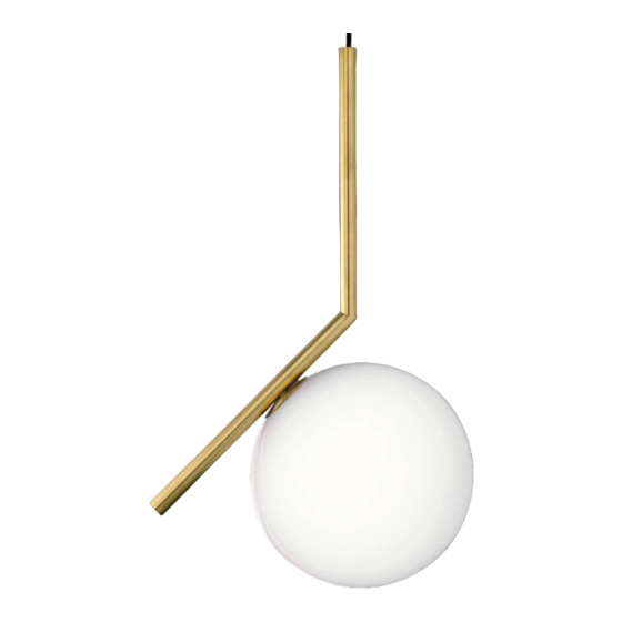
- Page 1 IC S1-S2 EUR DESIGN BY MICHAEL ANASTASSIADES...
-
Page 2: Cleaning Instructions
- Should the external trailing cable get damaged,it must impianto di messa a terra. be replaced by FLOS or by qualified personnel in order to - Se il cavo flessibile si danneggia, deve essere sostituito da avoid any danger. - Page 3 - Falls das flexible äußere Kabel beschädigt wird, muß - Si le cordon flexible externe est endommagé, il doit es von FLOS oder von qualifiziertem Personal ersetzt être remplacé par FLOS ou par le personnel qualifié afin werden, um Gefahren zu vermeiden. d’éviter des dangers.
- Page 4 - Si el cable externo se estropea, debe ser sustituido de ligação a terra. por FLOS o por personal cualificado con el fin de evitar - Se o cabo flexível está danificado, deve ser substituído situaciones peligrosas.
- Page 5 - В момент установки и каждый раз при проведении работ с устройством, убедиться в снятии напряжения питания. - Устройство не может изменяться или разбираться, любые изменения могут нарушить надёжность, делая его опасным. FLOS не несёт ответственность за измененную продукцию. - Для надежного и правильного функционирования данного устройства...
- Page 6 S1-S2 Fig. 1...
- Page 7 <IT> Fig.1 S1-S2 - Svitare le due viti senza testa (A) quindi separare l’attacco a muro (B) dal rosone (C) ruotandolo in senso antiorario per sganciarlo. <EN> Fig.1 S1-S2 - Unscrew the two headless screws (A) then separate the wall attachment (B) from the plate (C) rotating it anticlockwise to unfasten it.
- Page 8 Fig. 2a Fig. 2b...
- Page 9 <IT> Fig.2a S1 - Smontare il bloccacavo (F), scollegare il cavo di alimentazione (D) dalla morsettiera (E); Fig.2b S2 - Smontare il bloccacavo (F), scollegare il cavo di alimentazione (D) dalla morsettiera (E) e dal morsetto di terra (G). <EN> Fig.2a S1 - Dismount the cable lock (F), disconnect the power cable (D) from the terminal strip (E);...
- Page 10 Fig. 3 Fig. 4...
- Page 11 <IT> Fig.3 Fissare l’attacco a muro (B) con viti e tasselli ad espansione avendo cura di far passare i cavi di alimentazione provenienti dalla parete attraverso l’apposito foro (H); NOTA BENE: Utilizzare viti e tasselli idonei alla superfice destinata al montaggio. Fig.4 Effettuare i collegamenti elettrici nella morsettiera (E) e al morsetto di terra (I);...
- Page 12 Fig. 5a Fig. 5b...
- Page 13 <IT> Fig.5a S1 - Effettuare i collegamenti elettrici nella morsettiera (E) quindi bloccare il cavo rimontando il bloccacavo (F). Fig.5b S2 - Effettuare i collegamenti elettrici nella morsettiera (E) e al morsetto di terra (G)quindi bloccare il cavo rimontando il bloccacavo (F). <EN>...
- Page 14 Fig. 6...
- Page 15 <IT> Fig.6 Rimontare il rosone (C) sull’attacco a muro agganciandolo con una lieve rotazione in senso orario per poi bloccarlo riavvitando le viti senza testa (A). <EN> Fig.6 Remount the rose (C) on the wall attachment, fastening it with a slight clockwise rotation to then lock it by screwing the headless screws (A) back in.
- Page 16 Fig. 7...
- Page 17 <IT> Fig.7 Inserire la lampada quindi montare il diffusore (M) avvitandolo alla ghiera (N) del corpo apparecchio. NOTA: Le versioni S1 montano il diffusore 1 (diametro 200 mm), le versioni S2 montano il diffusore 2 (diametro 300 mm). <EN> Fig.7 Insert the bulb then mount the diffuser (M) screwing it to the device body’s ferrule (N).
- Page 18 <IT> DATI TECNICI VERSIONE IC S1 EUR Lampada incandescente ad alogeni MAX 60W attacco E14 tipo HSGS. IC S2 EUR Lampada incandescente ad alogeni MAX 205W attacco E27 tipo HSGS. <EN> TECHNICAL DATA VERSION IC S1 EUR Incandescent halogen bulb MAX 60W, E14 attachment type HSGS. IC S2 EUR Incandescent halogen bulb MAX 205W, E27 attachment type HSGS.
-
Page 19: Dados Técnicos
<ES> DATOS TECNICOS VERSIÓN IC S1 EUR Bombilla de incandescencia alógena MAX 60W conexión E14 tipo HSGS. IC S2 EUR Bombilla de incandescencia alógena MAX 205W conexión E27 tipo HSGS. <PT> DADOS TÉCNICOS VERSÃO IC S1 EUR Lâmpada incandescente alógena MAX 60W ligação E14 tipo HSGS. IC S2 EUR Lâmpada incandescente alógena MAX 205W ligação E27 tipo HSGS. - Page 20 www.flos.com...
Need help?
Do you have a question about the IC S1-S2 EUR and is the answer not in the manual?
Questions and answers