Table of Contents
Advertisement
Quick Links
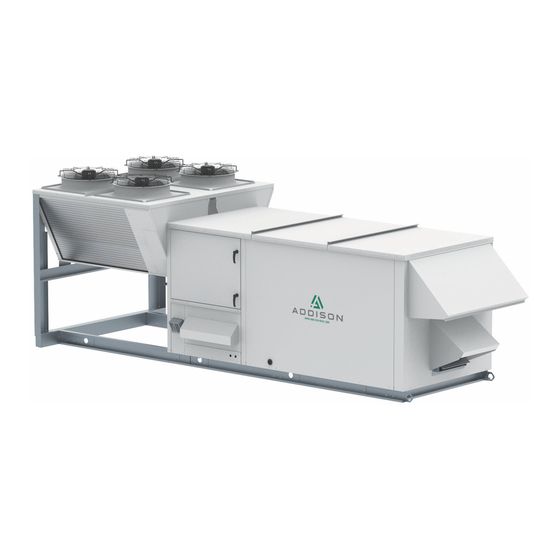
Rooftop DOAS &
Recirculation Unit
Installation, Operation,
& Maintenance Manual
PR**036
PR**060
PR**084
PR**120
PR**180
PR**240
PR**360
PR**480
PR**600
PR**780
NOTICE
Installer:
Please take the time to read and understand the
instructions contained inside this manual prior to
any installation. The installer must give a copy of this
manual to the unit owner.
Owner:
Keep this manual in a safe place in order to provide
service technicians with necessary unit information.
NOT FOR RESIDENTIAL USE
PR Series
Packaged
PR**048
PR**072
PR**096
PR**150
PR**210
PR**300
PR**420
PR**540
PR**720
PR**840
Advertisement
Table of Contents

Related Manuals for Addison PR Series


Summary of Contents for Addison PR Series
- Page 1 PR Series Packaged Rooftop DOAS & Recirculation Unit Installation, Operation, & Maintenance Manual PR**036 PR**048 PR**060 PR**072 PR**084 PR**096 PR**120 PR**150 PR**180 PR**210 PR**240 PR**300 PR**360 PR**420 PR**480 PR**540 PR**600 PR**720 PR**780 PR**840 NOTICE Installer: Please take the time to read and understand the instructions contained inside this manual prior to any installation.
- Page 2 This Page is Intentionally Blank...
-
Page 3: Table Of Contents
PR Series Installation, Operation, and Maintenance Manual Table of Contents: SECTION 1: Safety Introduction and Labeling Guide SECTION 13: Unit Electrical Warnings, Dangers, Cautions, and Notices ....5 13.1 Wiring and Electrical Connections ......41 Label Placement Guide ............6 13.2 Disconnect ................41 Sample Unit Data Plate............7... - Page 4 PR Series Installation, Operation, and Maintenance Manual Table of Figures: Figures: Figure 1: Label Placement Drawing ........6 Figure 2: Sample Unit Data Plate ........7 Figure 3: Large Unit Lifting ..........18 Figure 4: Medium Unit Lifting ..........19 Figure 5: Small Unit Lifting ..........20 Figure 6: Roof Curb Installation .........21...
-
Page 5: Section 1: Safety Introduction And Labeling Guide
PR Series Installation, Operation, and Maintenance Manual Section 1: WARNING Safety Introduction and Labeling Guide: Improper installation, service, or maintenance can Your Safety is Important to Us! result in death, injury, or property damage. Read this installation, operation, and maintenance manual Please follow and understand the rules and the thoroughly before installing or servicing this equipment. -
Page 6: Label Placement Guide
PR Series Installation, Operation, and Maintenance Manual Figure 1: Label Placement Drawing Part Number: Description: Location: Brand Logo Serial Data Plate 91070016 CA Prop 65 Label 91060002 R-410A Label 91070002 Fan Warning Label Quality Inspection Stamp 9-21577 Hot Surface Label... -
Page 7: Sample Unit Data Plate
PR Series Installation, Operation, and Maintenance Manual Figure 2: Sample Unit Data Plate PROA180C2B4D Model # Serial # 200300304001 Tag # DOAS-4 Unit Info. Test Pressure Max. Refrigerant Charge R410A Lbs. Volts Phase High Circuit #1 8.18 psig Circuit #2 8.18... -
Page 8: Section 2: Introduction And Pre-Installation
R-32 (Difluoromethane) and R-125 (Pentafluoroethane). DO NOT VENT HFC-(R410A) to The PR Series unit is a factory-assembled packaged the atmosphere. The U. S. Clean Air Act requires the system that can operate within a broad range of ambient recovery of any residual refrigerant. -
Page 9: Unit Nomenclature Example
PR Series Installation, Operation, and Maintenance Manual 2.3 - Unit Nomenclature Example Digit: Description: Feature: 1 - 2 Product Family PR = Packaged Rooftop O = Dedicated Outdoor Air Application M = Mixed Air (20% or Higher OA) R = Recirculating... - Page 10 PR Series Installation, Operation, and Maintenance Manual 2.3 - Unit Nomenclature Example, Cont. Digit: Description: Feature: Vintage D = Current A = Vertical supply and vertical return B = Horizontal supply and vertical return C = Vertical supply and side return...
- Page 11 PR Series Installation, Operation, and Maintenance Manual 2.3 - Unit Nomenclature Example, Cont. Digit: Description: Feature: 0 = None A = 5kW 240/480/575V - 3.75kW 208V B = 10kW 240/480/575V - 7.5kW 208V C = 15kW 240/480/575V - 11.25kW 208V D = 20kW 240/480/575V - 15kW 208V E = 25kW 240/480/575V - 18.75kW 208V...
- Page 12 PR Series Installation, Operation, and Maintenance Manual 2.3 - Unit Nomenclature Example, Cont. Digit: Description: Feature: 0 = None 1 = 1 Stage 2 = 2 Stage 3 = 4 Stage 9 = 8 Stage Heater Control 4 = SCR (N/A 5kW)
-
Page 13: Section 3: Installer Responsibility
PR Series Installation, Operation, and Maintenance Manual Section 3: WARNING Installer Responsibility: EXPLOSION HAZARD The installer is responsible for the following: Equipment must have access to uncontaminated air at all times. • To install and commission the unit, as well as the... -
Page 14: Section 4: Critical Considerations
PR Series Installation, Operation, and Maintenance Manual Section 4: Critical Considerations: 4.1 Required Clearances Clearances are the required distances that the unit must be away from objects and other units to allow service access and proper operation of the unit. -
Page 15: Unit Placement Considerations
PR Series Installation, Operation, and Maintenance Manual Table 1: Recommended Torque Settings 4.1.1 Service Clearances Minimum service clearance for service is based on cabinet size described in section 4.1. 4.1.2 Ventilation Clearances Bolt Head Grade Marking In order to help ensure proper operation of an air-source constructed unit, a 24"... -
Page 16: Section 5: National Standards And Applicable Codes
PR Series Installation, Operation, and Maintenance Manual Section 5: 5.6 Electrical National Standards and Electrical connection to unit must be in accordance with the following codes: Applicable Codes: United States: Refer to National Electrical Code®, NFPA 70 5.1 Refrigerant Handling Practices - latest revision. -
Page 17: Section 6: Lifting A Packaged Rooftop Unit
PR Series Installation, Operation, and Maintenance Manual Section 6: WARNING Lifting a Packaged Rooftop Unit: CRUSH HAZARD The unit must be installed in compliance with all Use proper lifting equipment and applicable codes. The qualified installer or service practices. Failure to follow these... -
Page 18: Figure 3: Large Unit Lifting
PR Series Installation, Operation, and Maintenance Manual Figure 3: Lifting a Large Unit (D & E Cabinets) ADJUST CABLE LENGTH TO LIFT POINTS AS NECESSARY,BASED ON UNIT CENTER OF GRAVITY SPREADER FIXED FIXED CABLE ROLLING BLOCK 20' CABLE THROUGH ROLLING BLOCK SEE DETAIL "B"... -
Page 19: Figure 4: Medium Unit Lifting
PR Series Installation, Operation, and Maintenance Manual Figure 4: Lifting a Medium Unit (C, CL, CXL Cabinets) SPREADER FIXED FIXED CABLE ADJUST CABLE LENGTH TO LIFT POINTS AS NECESSARY,BASED ON UNIT CENTER OF GRAVITY FORMED GALVANIZED SEE DETAIL "B" ADDITIONAL LIFT POINTS... -
Page 20: Figure 5: Small Unit Lifting
PR Series Installation, Operation, and Maintenance Manual Figure 5: Lifting a Small Unit (A & B Cabinets) ADJUST CABLE LENGTH TO LIFT POINTS AS NECESSARY,BASED ON UNIT CENTER OF GRAVITY FIXED SPREADER FIXED CABLE LIFTING POINTS BOTH SIDES FORMED DETAIL "C"... -
Page 21: Section 7: Unit Placement
PR Series Installation, Operation, and Maintenance Manual Section 7: NOTE: Check the installation location to ensure proper clearances to combustibles and clearance for access. Unit Placement: 7.3 Unit Mounting to Roof Curb 7.1 Roof Installation on Curb After the curb has been installed, the unit may be placed Roof curbs are available for units that are to be installed on the curb. -
Page 22: Section 8: Ductwork
PR Series Installation, Operation, and Maintenance Manual Section 8: 8.1 Inlet Ductwork Ductwork Consideration: Inlet ductwork height and width must be no smaller than the packaged air conditioning unit inlet height and width The unit has been designed to operate at the specific air and supply only uncontaminated air to the unit. -
Page 23: Section 9: Refrigeration Circuits And Piping
PR Series Installation, Operation, and Maintenance Manual Section 9: WARNING Refrigeration Circuits and Piping: EXPLOSION HAZARD 9.1 Refrigerant System contains R-410A refrigerant. Operating pressures This unit utilizes R-410A, a refrigerant with a zero ozone may exceed limits of R-22 service depletion rating, and POE (Copeland) or PVE (Bitzer) equipment. -
Page 24: Figure 7: Circuit Diagram For Standard Compressor
PR Series Installation, Operation, and Maintenance Manual Figure 7: Circuit Diagram for Standard Compressor with Hot Gas Bypass and No Hot Gas Reheat (PRRA Units Only) Page 24 of 84... -
Page 25: Figure 8: Circuit Diagram For Standard Compressor With Hot Gas Bypass And Modulating Hot Gas Reheat
PR Series Installation, Operation, and Maintenance Manual Figure 8: Circuit Diagram for Standard Compressor with Hot Gas Bypass and Modulating Hot Gas Reheat Page 25 of 84... -
Page 26: Figure 9: Circuit Diagram For Digital Compressor With Modulating Hot Gas Reheat
PR Series Installation, Operation, and Maintenance Manual Figure 9: Circuit Diagram for Digital Compressor with Modulating Hot Gas Reheat Page 26 of 84... -
Page 27: Figure 10: Circuit Diagram For Standard Compressor
PR Series Installation, Operation, and Maintenance Manual Figure 10: Circuit Diagram for Standard Compressor with Hot Gas Bypass, Modulating Hot Gas Reheat, and Subcooling Page 27 of 84... -
Page 28: Figure 11: Circuit Diagram For Digital Compressor
PR Series Installation, Operation, and Maintenance Manual Figure 11: Circuit Diagram for Digital Compressor with Modulating Hot Gas Reheat, and Subcooling Page 28 of 84... -
Page 29: Section 10: Energy Recovery/Conservation Wheels
PR Series Installation, Operation, and Maintenance Manual Section 10: DANGER Energy Recovery/Conservation Wheels: ELECTRICAL SHOCK HAZARD 10.1 Principal of Operation Disconnect electric before service. More than one disconnect switch The energy conservation wheel module is a self-contained may be required to disconnect unit consisting of the following components: electric from equipment. -
Page 30: Section 11: Gas Heater Packages
PR Series Installation, Operation, and Maintenance Manual Section 11: DANGER Gas Heater Packages: ELECTRICAL SHOCK HAZARD 11.1 Principle of Operation Disconnect electric before service. More than one disconnect switch The gas furnace is an 80% efficient, self-contained duct may be required to disconnect furnace that can burn natural gas or LPG. -
Page 31: Operating And Safety Controls
PR Series Installation, Operation, and Maintenance Manual 11.4 Wiring 11.3 Operating and Safety Controls All electric wiring and connections, including electrical Safety systems are required for proper performance of grounding, must comply with; the gas furnace. The gas furnace shall not be permitted to operate with any safety system disabled. - Page 32 PR Series Installation, Operation, and Maintenance Manual a 30 second post-purge period. If the thermostat 2. The control will check that pressure switch con- (controller) is still calling for heat one hour after a tacts are open (ignition control terminal PSW is not lockout occurs, the control will automatically reset and powered).
- Page 33 PR Series Installation, Operation, and Maintenance Manual 11.5.3 Sequence of Operation for 20-100% 10. If the controller is providing an analog signal between 0.5 and 5.3VDC to the SC30 control, the system will Modulating Furnace with 75-200 MBH (21.9- continue to run at low speed combustion blower and 58.6kW) Input...
- Page 34 PR Series Installation, Operation, and Maintenance Manual 11.5.4 Sequence of Operation for 20-100% 10. If the controller is providing an analog signal between 0.5 and 5.3VDC to the SC30 control, the system will Modulating Furnace with 250-400 MBH (73.3- continue to run at low speed combustion blower and 117.2 kW) Input...
-
Page 35: Figure 13: Example Gas Heater Wiring Diagram - 5:1 Modulation
PR Series Installation, Operation, and Maintenance Manual Figure 13: Example Gas Heater Wiring Diagram - 5:1 Modulation GAS FURNACE POWER SUPPLY FOR 208 VOLT UNITS (BUCKBOOST TRANSFORMER) BL‐14 BL‐14 SPLICE SPLICE SPLICE SPLICE BK‐14 BK‐14 3 Amps Fuses, SPLICE Y‐14 Class CC, GAS FURNACE #1 LINE 600volts, 100 VA VOLTAGE TERMINALS BK‐14 Time Delay (SEE FURNACE WIRING DIAGRAM) G‐14 Modulating Furnace Control Panel 230 VOLT, 1‐PHASE, 60‐HERTZ POWER SUPPLY WIRE TO ... -
Page 36: Figure 14: Example Gas Heater Wiring Diagram - 10:1 Modulation
PR Series Installation, Operation, and Maintenance Manual Figure 14: Example Gas Heater Wiring Diagram - 10:1 Modulation GAS FURNACE POWER SUPPLY FOR 208 VOLT UNITS (BUCKBOOST TRANSFORMER) BL‐14 BL‐14 SPLICE SPLICE SPLICE SPLICE BK‐14 BK‐14 3 Amps Fuses, SPLICE Y‐14 Class CC, GAS FURNACE #1 LINE 600volts, 100 VA VOLTAGE TERMINALS BK‐14 Time Delay (SEE FURNACE WIRING DIAGRAM) G‐14 Modulating Furnace Control Panel 230 VOLT, 1‐PHASE, 60‐HERTZ POWER SUPPLY WIRE TO ... -
Page 37: Figure 15: Example Gas Heater Wiring Diagram - Dual Furnace
PR Series Installation, Operation, and Maintenance Manual Figure 15: Example Gas Heater Wiring Diagram - Dual Furnace GAS FURNACE POWER SUPPLY FOR 460 VOLT UNITS Class CC, 4 amps fuse 600volts, Time Delay BL-14 BL-14 460V 1000 R-14 120V BK-14... -
Page 38: Section 12: Electric Heater Packages
PR Series Installation, Operation, and Maintenance Manual Section 12: DANGER Electric Heater Packages: ELECTRICAL SHOCK HAZARD 12.1 Principle of Operation Disconnect electric before service. More than one disconnect switch The electric heater is a self-contained duct heater may be required to disconnect comprised of: electric from equipment. -
Page 39: Table 3: Standard Electric Heaters
PR Series Installation, Operation, and Maintenance Manual Table 3: Standard Electric Heaters Minimum Maximum Minimum Maximum Model Function 1360 1600 2400 3200 1150 4000 1435 5000 1725 6000 2000 7000 OA & RA 2300 8000 10000 3450 12000 4025 14000... -
Page 40: Figure 16: Typical Electric Heater Wiring Diagram
PR Series Installation, Operation, and Maintenance Manual Figure 16: Typical Electric Heater Wiring Diagram Elec. Heat Enable See separate SCR or up to 4 Stage Elec. Heater Drawing Enable 1 Stage or SCR Heating Enable 2 Stage Heating Enable 3... -
Page 41: Section 13: Unit Electrical
PR Series Installation, Operation, and Maintenance Manual Section 13: DANGER Unit Electrical: ELECTRICAL SHOCK HAZARD Each unit is equipped with a wiring diagram (permanently Disconnect electric before service. attached behind clear view plastic on the inside of the More than one disconnect switch... -
Page 42: Figure 17: Typical Electrical Wiring Diagram
PR Series Installation, Operation, and Maintenance Manual Figure 17a: Typical Electrical Wiring Diagram MSP‐CC1 R‐10 R‐10 R‐10 BL‐10 BL‐10 BL‐10 BK‐10 BK‐10 BK‐10 CCH1 G‐14 R‐14 CC1‐A1 BK‐14 CURRENT SENSOR OUTDOOR FAN MOTOR VFD (OF1VFD)CONTROL TERMINAL STRIP CC1‐A1 OF1VFD CC2‐A1 MSP‐CC2 R‐10 R‐10 R‐10 BL‐10 BL‐10 BL‐10... - Page 43 PR Series Installation, Operation, and Maintenance Manual Figure 17b: Typical Electrical Wiring Diagram Line NOTE: SEE “T1” ON SHEET 1 96 VA NOTE: SEE “T3” ON SHEET 1 FOR WIRING CONTINUATION Voltage CLASS 2 FOR WIRING CONTINUATION 50/60HZ PM AUX 50/60HZ R‐14 R‐14 G‐14 G‐14 R‐14 BL‐14 R‐14 Remove jumper when field installed safeties are used UNLOADER SOLENOID #1 Enable Unloader #1 HPR1 1,2,3,4, Enable Compressor #1 HPR2 11,12,13, Enable Compressor #2...
- Page 44 PR Series Installation, Operation, and Maintenance Manual Figure 17c: Typical Electrical Wiring Diagram CONTINUED ON SHEET 2 BOS1 Enable Switchable Subcooling 138, 140 LSS1A N.O. N.C. LSS2A LSS1B N.O. N.C. LSS2B Enable Supply Fan SF1R Enable Hot Gas Reheat 134, 210 Elec. Heat Enable See separate 2‐Stage Elec. Heater Drawing Enable 1 Stage Heating Enable 2 Stage Heating OADA OADA Enable Outdoor Air Damper Actuator 24VAC WIRING DIAGRAM #PrelimWD | PROA180B2A3DEBDBB2B | 230‐3‐60 | SHEET 3 OF 7 | 12/10/19 DWN CHK ...
- Page 45 PR Series Installation, Operation, and Maintenance Manual Figure 17d: Typical Electrical Wiring Diagram REHEAT CONTROL VALVE (MUELLER VALVE) IF Mueller Valve is used wire as below REHEAT VALVE CAP PINK WIRE SEPARATELY UO‐4 0‐10VDC Output See ALC PAGE WIRE ALL SHIELD WIRES TO CLOSEST “GND” TERMINAL AT THE CONTROL PANEL PDB1 ELECTRIC HEATER LINE VOLTAGE TERMINALS (FUSED INTERNALY) USE USE ELECTRIC HEATER VENDORS RECOMMENDED WIRE SIZE WIRING DIAGRAM #PrelimWD | PROA180B2A3DEBDBB2B | 230‐3‐60 | SHEET 4 OF 7 | 12/10/19 DWN CHK Page 45 of 84...
- Page 46 PR Series Installation, Operation, and Maintenance Manual Figure 17e: Typical Electrical Wiring Diagram FIELD INSTALL EQUIPMENT TOUCH SEE TB4 ON UNIT LonWorks Card (optional) WIRING DIAGRAM Green Black Temp/RH White ZS Room To Wall Mount the Sensor Equipment Touch remove Port 2b ‐ the factory installed cable Power and wire +24VAC to TB4 “K3” 24VAC External and wire Gnd to TB4 “K4”. If 3V Litium Battery Battery CR‐123A there is a ZS sensor installed + 3V wire Rnet+ and Rnet‐ to the...
- Page 47 PR Series Installation, Operation, and Maintenance Manual Figure 17f: Typical Electrical Wiring Diagram SEE TB4 ON UNIT WIRING DIAGRAM 24VAC Gnd 16 Universal UI‐16 Inputs 9‐16 + 15 0‐5V Gnd 14 Therm/ Power UI‐15 + 13 Gnd 12 UI‐14 + 11 0‐5V Gnd 10 UI‐13 + 9 Therm/Dry Gnd 8 UI‐12 + 7 Gnd 6 UI‐11 + 5...
- Page 48 PR Series Installation, Operation, and Maintenance Manual Figure 17g: Typical Electrical Wiring Diagram LEGEND ‐ ITEMS INSIDE CONTROL PANEL LEGEND ‐ ITEMS OUTSIDE CONTROL PANEL FUNCTIONAL FUNCTIONAL ITEM LINE NUMBER DESCRIPTION ITEM LINE NUMBER DESCRIPTION DESIGNATION DESIGNATION Supply Fan Motor Contactor Air Pressure Switch (Supply Fan) Supply Fan Motor Relay 265, 266 Air Pressure Switch (Supply Fan and Exhaust Fan) MSP‐SF Motor Starter Protection‐Supply Fan BCTL BCTL SF‐VFD Supply Fan‐Variable Frequency Drive BOS1 Bleed‐Off Solenoid no. 1 Compressor Contactor no. 1 BOS1, BOS2 132, 134...
-
Page 49: Figure 18: Phase Monitor Data
Purpose General Operational Specifications The purpose of the DPM Line Voltages Monitored: 200 to 240VAC, 1Ø, 50/60Hz PR Series Installation, Operation, and Maintenance Manual (Digital Phase Monitor) is to 200 to 600VAC, 3Ø, 50/60Hz monitor the line voltage sup- Faults:... - Page 50 PR Series Installation, Operation, and Maintenance Manual Figure 18b: Phase Monitor Data Example: If you want to change the Re-Start Delay to 3 minutes (default is 2 minutes) and you are on the Default screen: 1. Press the Right arrow until you get to the Re-Start Delay screen 2.
-
Page 51: Section 14: Sequence Of Operation
PR Series Installation, Operation, and Maintenance Manual Section 14: DANGER Sequence of Operation: ELECTRICAL SHOCK HAZARD 14.1 Unit Configuration Disconnect electric before service. More than one disconnect switch Based on the unit's application, the unit may be may be required to disconnect configured in any number styles to achieve the described electric from equipment. -
Page 52: Basic Sequence Of Operation
PR Series Installation, Operation, and Maintenance Manual 14.3 Basic Sequence of Operation All sequence of operation information for units controlled with ALC controls is available in the ALC Sequence of Operation documents that can be downloaded from the Addison website at www.addison-hvac.com. -
Page 53: Section 15: Start-Up Procedure
Addison Equipment must always be and conform to all requirements set forth in the Addison properly grounded. manuals and all applicable governmental authorities pertaining to the installation, service operation and SEVERE INJURY HAZARD labeling of the equipment. -
Page 54: Figure 20: P-Trap Configuration
PR Series Installation, Operation, and Maintenance Manual Figure 20: P-Trap Configuration CAUTION! Drain Pan Condensate traps must be installed based on the guidelines below. Units must also be level, or slightly inclined towards the drain. Failure to follow these guidelines could cause condensate not to drain properly, and potential intrusion of water into the space. -
Page 55: Table 6: Hot Water Heating Coil Flow Rate
PR Series Installation, Operation, and Maintenance Manual Table 6: Hot Water Heating Coil Flow Rate and Pressure Drop Nominal GPM Pressure Drop Connection Size Model Cabinet (Water Only) (FT, H2O) (Sweat, in.) 096 - 120 50.0 4.31 1-5/8 150 - 210 70.0... -
Page 56: Table 10: Refrigerant Temperature-Pressure
PR Series Installation, Operation, and Maintenance Manual Table 10: Refrigerant Temperature-Pressure Chart (PSIG) Temp Temp Temp Temp R-22 R-134A R-410A R-22 R-134A R-410A °F °C °F °C 14.8(“Hg) 10.8 60.0 101.6 57.4 170.7 16.0 13.9(“Hg) 12.1 62.0 105.4 60.0 176.6 17.0... -
Page 57: Pre-Start Form
EXPLOSION HAZARD service of equipment sold and supplied by Addison and System contains R-410A conform to all requirements set forth in the Addison manuals refrigerant. Operating pressures and all applicable governmental authorities pertaining to the may exceed limits of R-22 service installation, service, operation and labeling of the equipment. - Page 58 PR Series Unit Pre-Start Form PRE-START CHECKLIST ☐ ☐ Documentation to properly start the unit including Electrical connections are tight. the sequence of operation, and a copy of the work ☐ order listing complete unit configuration. Overloads are adjusted. ☐...
- Page 59 Do not operate with service of equipment sold and supplied by Addison and access doors open. Installation, conform to all requirements set forth in the Addison manuals operation, and maintenance and all applicable governmental authorities pertaining to the must be performed by a trained installation, service, operation and labeling of the equipment.
-
Page 60: Start-Up Form
R-22 service service of equipment sold and supplied by Addison and equipment. Use proper refrigerant conform to all requirements set forth in the Addison manuals handling practices, tools, and and all applicable governmental authorities pertaining to the equipment. - Page 61 PR Series Unit Start-Up Form GENERAL INFORMATION Project Name: Customer Name: Contractor Name: Address: Unit Model #: City/State/Zip: Unit Serial #: Phone/Fax: Unit Tag #: APPLICATION INFORMATION Outdoor Air Supply Air Temp (°F or °C): Temp (°F or °C): Return Air Outdoor Fan Temp (°F or °C):...
- Page 62 PR Series Unit Start-Up Form UNIT INFORMATION Condenser Fan Motor: Make: Model: Voltage: AMPS: Quantity: Energy Conservation Wheel Motor: Make: Model: Voltage: AMPS: Unit Compressors: Manufacturer: C1A - Model Number: Serial Number: Nameplate: Voltage: C1B -Model Number: Serial Number: Phase:...
- Page 63 PR Series Unit Start-Up Form START-UP CHECK Supply Fan: (AMPS) (AMPS) (AMPS) (inWG) Command % or RPM Exhaust Fan: (AMPS) (AMPS) (AMPS) (inWG) Notes: Command % or RPM 1. Taken from field supply ductwork. 2. Taken from field Energy Recovery Wheel: return ductwork.
- Page 64 PR Series Unit Start-Up Form COOLING CHECK Compressor Circuit #2: Suction Pressure: Suction Temp: Saturation Temp: Discharge Pressure: Discharge Temp: Saturation Temp: Liquid Pressure: Liquid Temp: To Calculate Superheat: Convert suction pressure to saturation temperature, Superheat: then subtract the suction line temperature.
- Page 65 PR Series Unit Start-Up Form HEATING CHECK Heat Pump: Heating Type: Hot Water: Electric: Gas: Gas Type: Heat Stages - Qty: Manifold Pressure: Modulating Type: Electric Heat AMPS: Water Water Glycol Water Source Coil: In °F: Out °F: Water Water...
-
Page 66: Installation Code And Quarterly Inspections
Addison must be performed by a trained and conform to all requirements set forth in the Addison technician only. manuals and all applicable governmental authorities Failure to follow these instructions can result in pertaining to the installation, service, operation and death, electrical shock, or injury. -
Page 67: General
PR Series Installation, Operation, and Maintenance Manual Table 11: Maintenance Guidelines 17.1 General Follow the entire start-up procedure at this time and check settings (controls, operating Quarterly temperatures, operating pressures, power and control voltages) and operation. 17.2 Unit Exterior After installation, touch up scratches. Periodic painting should be done thereafter Cabinet Exterior as required. -
Page 68: Section 18: Replacement Parts
PR Series Installation, Operation, and Maintenance Manual Section 18: DANGER Replacement Parts: ELECTRICAL SHOCK HAZARD Only genuine Addison replacement parts should be used. Disconnect electric before service. More than one disconnect switch Replacement parts used in units with the harsh environment may be required to disconnect coating option must be coated before being installed. -
Page 69: Table 12: Air Filters
PR Series Installation, Operation, and Maintenance Manual Table 12: Air Filters Model Size Coil Size Filter Size Quantity PROA 036, 048, 060 20 x 20 24 x 24 x 2 PRRA PROA 072, 084, 096 20 x 34 24 x 24 x 2... -
Page 70: Section 19: Troubleshooting
Equipment must always be and service of equipment sold and supplied by Addison properly grounded. and conform to all requirements set forth in the Addison SEVERE INJURY HAZARD manuals and all applicable governmental authorities Do not enter equipment while in pertaining to the installation, service, operation and operation. -
Page 71: Supply Fan
PR Series Installation, Operation, and Maintenance Manual Table 13.1: Supply Fan Problem Probable Cause Solution Damper limit switch not closed Repair or replace switch or inoperative Motor thermal overloads tripped For tripped condition-reset Blower Motor Does Not Run Fuses blown or missing... -
Page 72: Compressor
PR Series Installation, Operation, and Maintenance Manual Table 13.2: Compressor Problem Probable Cause Solution Power off, loose electrical connections or Check disconnect switch, fuses and wiring fuse open Check voltage to contactor coil, transformer Compressor contactor not closing slave relay, thermostat If compressor is hot, allow 2 hours to cool –... - Page 73 PR Series Installation, Operation, and Maintenance Manual Table 13.2: Compressor, Cont. Problem Probable Cause Solution Check incoming voltage leg-to-leg All three legs must be within 10% of the Low voltage required voltage and the leg-to-three-leg average voltage variation must be less than...
-
Page 74: Refrigeration Circuit
PR Series Installation, Operation, and Maintenance Manual Table 13.3: Refrigeration Circuit Problem Probable Cause Solution Air noise Check ductwork Air Velocity too high Check for adequate control voltage, check Chattering contactor for shorts or breaks, check thermostat, Noisy Operation check contactor points... - Page 75 PR Series Installation, Operation, and Maintenance Manual Table 13.3: Refrigeration Circuit, Cont. Problem Probable Cause Solution Check thermostat, check heat Thermostat location or malfunction anticipator setting Improper refrigerant charge Check subcooling, verify superheat Defective high or low pressure control Check high or low pressure switch...
-
Page 76: Variable Speed Head Pressure Control
PR Series Installation, Operation, and Maintenance Manual Table 13.4: Variable Speed Head Pressure Control Problem Probable Cause Solution No 24V control voltage Check for 24 VAC at control Check alignment of capillary fitting Schrader valve depressor must depress No input pressure to control... - Page 77 PR Series Installation, Operation, and Maintenance Manual Table 13.4: Variable Speed Head Pressure Control, Cont. Problem Probable Cause Solution Regulator seat is restricted Locate and remove stoppage, install strainer Pressure adjusting stem is set at a point so high that suction pressure never reaches...
-
Page 78: Energy Conservation Wheel
PR Series Installation, Operation, and Maintenance Manual Table 13.5: Energy Conservation Wheel Problem Probable Cause Solution Incorrect wheel rotation speed Check wheel rotation speed Worn wheel media or worn/out-of-place Check wheel integrity and seals seals Adjust and/or replace seals Inadequate Wheel... -
Page 79: Gas Furnace
PR Series Installation, Operation, and Maintenance Manual Table 13.6: Gas Furnace LED flashes on for 1/4 second and off for 1/4 second during fault condition. Pause between fault codes is 3 seconds. Problem Probable Cause Solution Steady On-No Internal control fault... -
Page 80: Electric Heater
PR Series Installation, Operation, and Maintenance Manual Table 13.7: Electric Heater Problem Probable Cause Solution Check that the controls are set to call No call for heat for heating Check that heater has power and No Heat No power and control voltage to heater... -
Page 81: Section 20: Addison Warranty
The following is the Limited Warranty provided by purchase date and required annual maintenance Addison (a trade name of Addison HVAC LLC, herein history, the data plate and/or serial number on any “Seller”) to any customer (herein “Buyer”) for any goods deliverable is removed, defaced, modified or altered and services (a “deliverable”):... - Page 82 PR Series Installation, Operation, and Maintenance Manual Except as set forth in these terms, Seller makes no representation or warranty of any type, express or implied, including any warranty of merchantability, warranty of fitness for a particular purpose or warranty of non-infringement or warranty arising from any course of dealing, course of performance or usage of trade.
-
Page 83: Revision Guide
PR Series Installation, Operation, and Maintenance Manual Revision Guide: Date: Page: Description: 19 Jun 20 Combined all previous IOMs into new format 19 Jun 20 Multiple updates, additions, and clarifications Page 83 of 84... - Page 84 We’re On a Mission to Create Solutions For Safer, Healthier, and More Productive Indoor Environments DEDICATED OUTDOOR AIR SPECIALISTS 7050 Overland Road Orlando, FL 32810 Tel.: 407-292-4400 ∙ Fax: 407-290-1329 www.addison-hvac.com Part Number: AD-IOM-PR-001 Rev.: 19 June 2020DS *AD-IOM-PR-001* © Addison 2020...
Need help?
Do you have a question about the PR Series and is the answer not in the manual?
Questions and answers