Table of Contents
Advertisement
Advertisement
Table of Contents

Related Manuals for ADTRAN T1 CSU ACE


Summary of Contents for ADTRAN T1 CSU ACE
- Page 1 T1 CSU ACE Part Number 1203022L1 Document Number 61203022L1-1B August 2004...
- Page 2 ADTRAN reserves the right to change the contents without prior notice. In no event will ADTRAN be liable for any special, incidental, or consequential damages or for commercial losses even if ADTRAN has been advised thereof as a result of issue of this publication.
-
Page 3: Save These Important Safety Instructions
Notes provide additional useful information. Cautions signify information that could prevent service interruption. Safety Instructions When using your telephone equipment, please follow these basic safety precautions to reduce the risk of fire, electrical shock, or personal injury: 1. Do not use this product near water, such as a bathtub, wash bowl, kitchen sink, laundry tub, in a wet basement, or near a swimming pool. - Page 4 Affidavit Requirements for Connection to Digital Services • An affidavit is required to be given to the telephone company whenever digital terminal equipment without encoded analog content and billing protection is used to transmit digital signals containing encoded analog content which are intended for eventual conversion into voiceband analog signals and transmitted on the network.
- Page 5 Affidavit for Connection of Customer Premises Equipment to 1.544 Mbps and/or Subrate Digital Services For the work to be performed in the certified territory of ___________________ (telco name) State of ________________ County of ________________ I, _______________________ (name), ____________________________________ (business address), ____________________ (telephone number) being duly sworn, state: I have responsibility for the operation and maintenance of the terminal equipment to be connected to 1.544 Mbps and/or ________ subrate digital services.
- Page 6 4. If experiencing difficulty with this equipment, please contact ADTRAN for repair and warranty information. The telephone company may require this equipment to be disconnected from the network until the problem is corrected or it is certain the equipment is not malfunctioning.
- Page 7 7. The following information may be required when applying to the local telephone company for a dial-up line for the V.34 modem: Service Type 1.544 Mbps - SF 1.544 Mbps - SF and B8ZS 1.544 Mbps - ESF 1.544 Mbps - ESF and B8ZS 8.
-
Page 8: Federal Communications Commission Radio Frequency Interference Statement
Federal Communications Commission Radio Frequency Interference Statement This equipment has been tested and found to comply with the limits for a Class A digital device, pursuant to Part 15 of the FCC Rules. These limits are designed to provide reasonable protection against harmful interference when the equipment is operated in a commercial environment. -
Page 9: Canadian Emissions Requirements
Industry Canada Compliance Information Notice: The Industry Canada label applied to the product (identified by the Industry Canada logo or the “IC:” in front of the certification/ registration number) signifies that the Industry Canada technical specifications were met. Notice: The Ringer Equivalence Number (REN) for this terminal equipment is supplied in the documentation or on the product labeling/ markings. -
Page 10: Warranty And Customer Service
Warranty and Customer Service ADTRAN will repair and return this product within 5 years from the date of shipment if it does not meet its published specifications or fails while in service. For detailed warranty, repair, and return information refer to the ADTRAN Equipment Warranty and Repair and Return Policy Procedure. - Page 11 EXCLUSION OF IMPLIED WARRANTIES, SO THIS EXCLUSION MAY NOT APPLY TO CUSTOMER. In no event will ADTRAN or its suppliers be liable to the Customer for any incidental, special, punitive, exemplary or consequential damages experienced by either the Customer or a third party (including, but not limited to, loss of data or information, loss of profits, or loss of use).
- Page 12 Customer Service, Product Support Information, and Training ADTRAN will repair and return this product if within 5 years from the date of shipment the product does not meet its published specification or the product fails while in service. A return material authorization (RMA) is required prior to returning equipment to ADTRAN.
- Page 13 Post-Sale Support Your reseller should serve as the first point of contact for support. If additional support is needed, the ADTRAN Support web site provides a variety of support services such as a searchable knowledge base, updated firmware releases, latest product documentation, service request ticket generation and trouble-shooting tools.
- Page 14 ADTRAN’s product lines. ADTRAN provides a variety of training options, including customized training and courses taught at our facilities or at your site. For more information about training, please contact your Territory Manager or the Enterprise Training Coordinator.
-
Page 15: Table Of Contents
Network Connector Type ....... . 37 61203022L1-1B T1 CSU ACE User Manual... - Page 16 Index ........... .39 T1 CSU ACE User Manual...
-
Page 17: List Of Figures
T1 CSU ACE Power Supply ..... 23 Figure 4. T1 CSU ACE LED Alarms ..... . . 24 Figure 5. - Page 18 List of Figures T1 CSU ACE User Manual 61203022L1-1B...
-
Page 19: List Of Tables
Table 5..........31 61203022L1-1B T1 CSU ACE User Manual... - Page 20 List of Tables T1 CSU ACE User Manual 61203022L1-1B...
-
Page 21: Chapter 1 General
General Chapter 1 UNIT OVERVIEW The ADTRAN T1 Channel Service Unit (CSU) Advanced Communications Equipment (ACE) provides the T1 interface between customer premises equipment (CPE) such as channel banks, T1 multiplexers, and the carrier network as shown in Figure 1. The unit complies with Part 68 of FCC Rules and with applicable sections of AT&T 62411, ANSI T1.102 and ANSI T1. - Page 22 Chapter 1. General Figure 2. T1 CSU ACE Block Diagram T1 CSU ACE User Manual 61203022L1-1B...
-
Page 23: Power Options
POWER OPTIONS The T1 CSU ACE may receive power from a local power supply located on the customer’s premises. Local power can be supplied by the customer’s own 12 to 48 volt supply, or by the wallmount power supply shipped with the unit (see Figure 3). The wall mount power supply is an NEC class 2 device. -
Page 24: Alarms
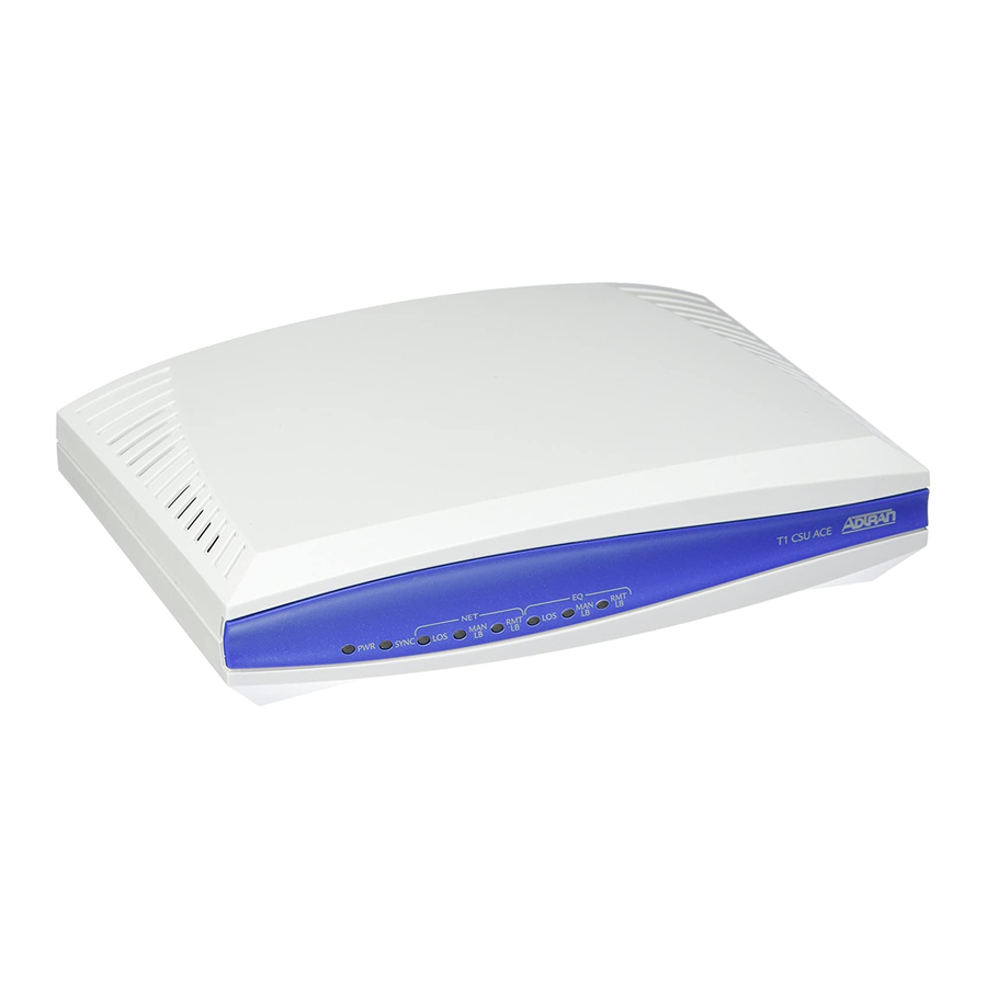
Chapter 1. General ALARMS The T1 CSU ACE provides five LED alarms on the front of the unit to help troubleshoot the communication channel. See Figure 4. The alarm descriptions are as follows: • The POWER LED shows that the unit is receiving power. -
Page 25: Loopback
LOOPBACK The T1 CSU ACE supports four types of loopbacks. With the first two, the unit loops the signal received from the network back to the network and transmits an unframed all 1s pattern to the CPE. The signal received from the CPE is ignored. -
Page 26: Line Build Out
Figure 5. T1 CSU ACE Loopback Switch and LED LINE BUILD OUT The first five positions of the switch on the back of T1 CSU ACE selects Line Build Out (LBO). See Figure 6. Separate LBOs set the transmit levels for the network and CPE sides of the T1 CSU ACE. The receivers on both sides of the CSU ACE contain Automatic Line Build Out (ALBO) circuitry to compensate for loss. -
Page 27: Chapter 2 Installation
61203022L1-1B ch position se Down Down Down Down POSITION 4 POSITION 5 CABLE LENGTH Down Down Down Down Down Down Down T1 CSU ACE User Manual ttings are defined in Ta- ATTENUATION (dB) 22.5 (feet) 0-133 134-265 266-399 400-533 534-655... -
Page 28: Wallmounting The Unit
Chapter 2. Installation WALLMOUNTING THE UNIT The T1 CSU ACE may be installed in a wallmount or tabletop configuration. The following section provides step-by-step instructions for wallmounting the unit . Instructions for Wallmounting Step Decide on a location for the T1 CSU ACE. Mount the unit at or below eye-level so that the LEDs are viewable. - Page 29 Chapter 2. Installation Figure 7. Wallmounting the T1 CSU ACE 61203022L1-1B T1 CSU ACE User Manual...
-
Page 30: Powering The Unit
Two 8-pin modular connectors are located on the back of the T1 CSU ACE (see Figure 8 on page 32). NET connects the unit to the network via the network cable. The connector marked CPE connects the cable from the customer equipment to the T1 CSU ACE. Method 1 Method 2... - Page 31 Notify the carrier before connecting the T1 CSU ACE to the carrier net- work. Connect the T1 CSU ACE to the network demarcation before con- necting to the CPE . Connector pin assignments for the Net RJ48C are listed in Table 4. Connector pin assignments for the CPE 8-Pin modular jack are listed in Table 5.
-
Page 32: Test And Monitor Access
Chapter 2. Installation TEST AND MONITOR ACCESS The six Bantam jacks located on the back of the T1 CSU ACE provide test and monitor access for the network and equipment side of the T1 CSU ACE. The diagram on the face of the unit shows each jack’s function, as seen in Figure 8. -
Page 33: Break-And-Test Jacks
NET OUT are used to simulate the network input and output of the T1 CSU ACE. To test the CPE, a T1 Bit Error Rate Test (BERT) test set can be used to simulate the network. EQ IN and EQ OUT can be used to sim- ulate the CPE with a BERT test set, allowing the network to be tested. - Page 34 Chapter 2. Installation T1 CSU ACE User Manual 61203022L1-1B...
-
Page 35: Chapter 3 Troubleshooting And Maintenance
Condition: NET LOS LED is illuminated. Verify that the cable from the network demarcation is in NET modular jack on the bottom/end of the T1 CSU ACE. If all connections seem intact, the far end CSU ACE can be looped back (using a BERT test set to send the LB code, or using MANUAL LB at the other end) to isolate the problem to the far end customer premises or the network. -
Page 36: Equipment Los
MAINTENANCE The T1 CSU ACE requires no routine maintenance. No repairs should be performed by the customer. Repair services can be obtained by re- turning the unit to the ADTRAN Customer and Product Service (CAPS) department as instructed on page 12. -
Page 37: Chapter 4 Specifications
8-pin modular (RJ48C). Customer Interface Connector Type 8-pin modular jack. LED INDICATORS Power is On. SYNC Signal from network and CPE present. Net LOS Loss of Signal from network. NET MAN LB Network manual loopback 61203022L1-1B T1 CSU ACE User Manual... -
Page 38: Relative Humidity
Local Power 35 mA typ. at 48 V. 90 mA typ. at 12 V. ENVIRONMENTAL Temperature Operating 0 C to 50 C. Storage -20 C to 70 C. Relative Humidity Up to 95% (non-condensing). T1 CSU ACE User Manual 61203022L1-1B... - Page 39 Power, problems 35 Power, specifications 38 Powering the Unit 30 Setting the LBO switch positions 27 Signal Format 37 Specifications 37 SYNC, alarm 24 T1 CSU ACE, overview 21 Temperature, storage and operation 38 T1 CSU ACE User Manual rack 28...
- Page 40 Index test and monitor access 31 Troubleshooting 35 61202022L1-1B Unit overview 21 T1 CSU ACE User Manual...
Need help?
Do you have a question about the T1 CSU ACE and is the answer not in the manual?
Questions and answers