
Related Manuals for AVCOM PSA-37XP


Summary of Contents for AVCOM PSA-37XP
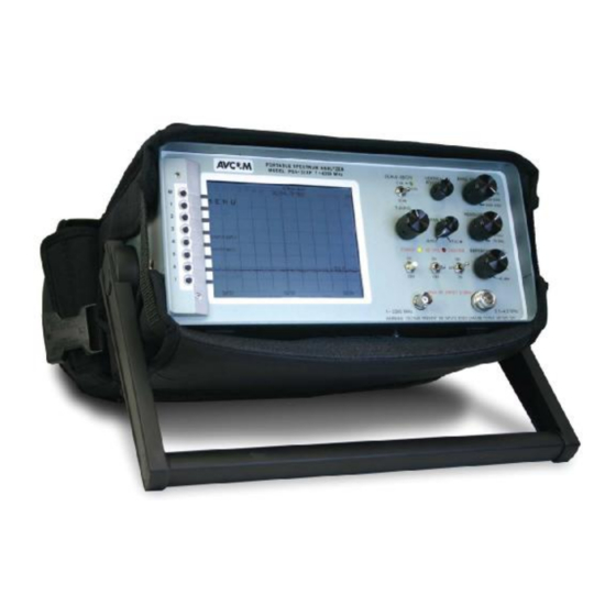
- Page 1 PSA-37XP Portable Spectrum Analyzer for: Owner’s Manual AVCOM of Virginia, Inc. 7730 Whitepine Road Richmond, VA 23237 USA 804-794-2500 www.avcomofva.com...
-
Page 2: Table Of Contents
AVCOM Publication No. PSA37XP Revision 5 April 2007 PSA-37XP ( owners manual) TABLE OF CONTENTS Inputs, Outputs, and Controls......4 Menu Quick Reference ........8 Initial Menu ............10 Start-Up Menu ............. 11 Operation Menu........... 18 Preliminary Operation......... 24 Band Aid Operation ..........25 MFC Operation ............ - Page 3 +18 VDC. If in doubt, consult the manufacturer of the component. 2. Do not couple the input of the PSA-37XP to high power RF sources such as walkie-talkies, CB radios, transmitters, etc. Signal levels in excess of 0 dBm can damage the sensitive mixers in the instrument re- sulting in otherwise unnecessary expense and repairs.
-
Page 4: Inputs, Outputs, And Controls
WARNING! Voltage is present on this jack when the LNA/LNB power switch is in either the 13V or 18V position. C. POWER Switch Use this button to turn the PSA-37XP ON or OFF D. 22KHz Switch This switch puts a 22KHz signal on connectors when the LNA/LNB Power is applied E. - Page 5 I. TUNING Knob Tunes the PSA-37XP through the selected band and centers signals of interest on the display while their frequency is shown at the top center of the display. J. SPAN WIDTH Knob Controls the sweep width of the Spectrum Analyzer.
- Page 6 It is also used as a cord wrap for the AC/DC power cables. Q. RS-232 The RS-232 jack is provided for remote control of the PSA-37XP and also firmware updates. The standard baud rate for communications is 115Kbps. See USER OPTIONS - Serial Port Options.
- Page 7 V. WEB PAGE You can access more information on the AVCOM products on the internet. Please visit www.avcomofva.com. W. MFC .1-2.1 GHZ OUTPUT The BNC jack is used for output frequency from 0.1 to 2.1 GHz in high frequency ranges.
- Page 8 A. MENU Buttons These buttons are used to control the menu structure of the PSA -37XP. B. MENU Structure This is the actual menu structure used in configuring the unit. As the MENU Buttons are pressed, the value, or menu structure will change accordingly. C.
- Page 9 E. SPAN Width The value of this is determined by the SPAN WIDTH Knob and shows the MHz/div chosen. F. MENU SELECTION Value This shows the value of the chosen menu selection. In the above reference, it shows the value of the screen contrast.
-
Page 10: Initial Menu
MENU STRUCTURE REFERENCE INITIAL MENU: This menu is only seen on the initial boot of the spectrum analyzer Button Label Description MENU Takes you to the standard menu structure of the ana- lyzer only at startup Enters into a menu structure that is only available at the first boot of the spectrum analyzer. - Page 11 This affects the Frequency Counter display on the top and bottom of the analyzer screen center_f User calibration of the center frequency trim_UP center_f User calibration of the center frequency trim_DOWN mode Used only in conjunction with an AVCOM MFC See Frequency Extender Operation Section...
- Page 12 MENU STRUCTURE REFERENCE STARUP MENU: 3 Button Label Description MENU>> -3 Changes to the next higher menu in the structure MENU<< Changes to the next lower menu in the structure ride peak Continually finds the peak value and updates the dis- play to reflect the new trace alarm(s) Turns on the ability to set alarms...
- Page 13 MENU STRUCTURE REFERENCE STARUP MENU: 4 Button Label Description MENU>> -4 Changes to the next higher menu in the structure MENU<< Changes to the next lower menu in the structure Not Used Not Used show dB+X dB Offset — used to enter a known offset for cable length attenuation.
- Page 14 MENU STRUCTURE REFERENCE STARUP MENU: 5 Button Label Description MENU>> -5 Changes to the next higher menu in the structure MENU<< Changes to the next lower menu in the structure frequency Displays a vertical marker created at the current cen- markers on/OFF ter frequency setting.
- Page 15 MENU STRUCTURE REFERENCE STARUP MENU: 6 Button Label Description MENU>> -6 Changes to the next higher menu in the structure MENU<< Changes to the next lower menu in the structure Not Used Internal MFC on/OFF To turn ON or Off the internal MFC Internal MFC adjust + For internal MFC adjust, this screen shows up Only when the internal MFC is ON position...
- Page 16 MENU STRUCTURE REFERENCE STARUP MENU: 7 Button Label Description MENU>> -7 Changes to the next higher menu in the structure MENU<< Changes to the next lower menu in the structure Not Used 03:42:14 Display of actual time time ON/off Turns the time display on the screen either ON or OFF bump HOUR Increases the value of the HOUR position bump MIN...
- Page 17 MENU STRUCTURE REFERENCE STARUP MENU: 8 Button Label Description MENU>> -8 Changes to the next higher menu in the structure MENU<< Changes to the next lower menu in the structure Not Used Aug 23, 2004 Display of actual date date ON/off Turns the date display on the screen either ON or OFF bump MONTH Increases the value of the MONTH position...
-
Page 18: Operation Menu: 0
MENU STRUCTURE REFERENCE OPERATION MENU: 0 Button Label Description next Changes to menu 1 menu m0: traceA->B Freezes the current trace to the background hide B / view B Removes background trace / Displays last background trace. hide A / view A Removes active trace from the display / Shows the active trace on the display. - Page 19 MENU STRUCTURE REFERENCE OPERATION MENU: 1 Button Label Description next Changes to menu 2 menu m1: mem 01 Non-Volatile memory locations to save trace informa- tion. Used to Recall or Save active screen traces. mem 02 mem 03 mem 04 mem 05 next five Up to 50 memory locations...
- Page 20 MENU STRUCTURE REFERENCE OPERATION MENU: 2 Button Label Description next Changes to menu 3 menu m2: show dBm Default display of reading on the right of the analyzer screen show dBmv Changes right display to dBmv for specific applications mode dB Determines display and value displayed in dB on right normal / hidden / adding X / hiding +X of analyzer screen...
- Page 21 MENU STRUCTURE REFERENCE OPERATION MENU: 3 Button Label Description next Changes to menu 4 menu m3: find peak Finds and hold the peak trace in the background of the screen ride peak Continually finds the peak value and updates the dis- play to reflect the new trace freq lock Default ON—Gives the user the ability to turn off Fre-...
- Page 22 MENU STRUCTURE REFERENCE OPERATION MENU: 4 Button Label Description next Changes to menu 5 menu m4: contrast + Increases the value of screen contrast. Adjust for user preference. contrast— Decreases the value of screen contrast. Adjust for user preference. videoFlip Displays a negative image of the screen band aid Applies fixed offsets for displayed frequencies.
- Page 23 MENU STRUCTURE REFERENCE OPERATION MENU: 5 Button Label Description next Changes to menu 0 menu m5: SCOM Off Turns Serial Communication ON/OFF. Available in units manufactured or upgraded after January 1st, 2005...
- Page 24 OPERATION Preliminary Checkout and User Familiarization 1. Plug DC plug from supplied power brick into the DC jack on the rear of the PSA -37XP. 2. Plug the AC plug from the supplied brick into the outlet. 3. Note that green POWER LED is blinking which indicates the battery charge operation is working. 4.
- Page 25 OPERATION BAND AID INTRODUCTION AND SETUP The PSA-37XP has a built in feature for viewing down-converted KU-Band. Normally, the KU-Band fre- quencies are stepped down to L-Band frequencies and displayed on the analyzer. With the BAND AID Function, you will be able to view the frequencies on the frequency counter as they truly are. The PSA - 37XP has implemented this feature to aid in the field installation processes utilizing th eAVCOM portable spectrum analyzers.
- Page 26 MFC and the analyzer. Each MFC is manufactured for a specific ana- lyzer and can not be interchanged, however, the AVCOM MFC can be developed for any manufacturer model of spectrum analyzers. Please contact AVCOM Customer Care for more information.
- Page 27 OPERATION INTERNAL FREQUENCY EXTENDER INSTRUCTIONS 1. Attach input from extended frequency source to the “MFC INPUT” jack on the rear panel. 2. Attach cable from “MFC 0.1 - 2.1 GHz OUTPUT” jack on the rear panel to the “1 – 2200 MHz” input jack on the front panel (see photo below).
-
Page 28: Specifications
6 hour battery life) • Stand: Bottom mounted aluminum feet attached • Supplied Accessories: 110 VAC EIA power cord, whip antenna, one BP3010 Li-Ion battery • Case color: AVCOM green wet coat • Dimensions: 11.5”W x 5.5”H x 13.5”D • Weight: 12lbs... -
Page 29: Battery Information
Lithium Ion batteries will also not deliver full current capacity at low temperatures, so depending on fea- tures used in the PSA-37XP, it may or may not power up below –2C. If you warm the PSA-37XP inside of a vehicle for instance, once powered up the battery will warm itself during the discharge cycle. - Page 30 Your PSA-37XP includes one Li-Ion battery pack, with the option of one additional battery packs. These battery packs have been installed in the rear battery chamber, but have been unplugged for shipping. Upon receipt of your PSA-37XP, please remove the rear battery chamber cover and plug in each battery pack.
-
Page 31: Frequency Allocation Charts
STANDARD FREQUENCY ALLOCATION CHARTS Band Name Abbreviation Frequencies Below 2 Hz Extremely low frequency 3-300 Hz Ultra low frequency 300-3000 Hz Very low frequency 3-30 kHz Low frequency 30-300 kHz Medium frequency 300-3000 kHz High frequency 3-30 MHz Very high frequency 30-300 MHz Ultra high frequency 300-3000 MHz... - Page 32 KEY DEFINITIONS Extremely low frequency or ELF refers to the band of radio frequencies from 3 to 300Hz. Very low frequency or VLF refers to radio frequencies (RF) in the range of 3 to 30 kHz. Low Frequency or LF refers to Radio Frequencies (RF) in the range of 30-300 kHz. Medium frequency or MF refers to radio frequencies (RF) in the range of 300 -3000 kHz.
- Page 33 AVCOM shall not be liable for cost of repairs or replacement of parts or components due to physical damage, product misuse or abuse and unauthorized modifications or repair.
- Page 34 AVCOM of Virginia, Inc. 7730 Whitepine Road Richmond, VA 23237 Phone (804) 794-2500 Fax (804) 794-8284 www.avcomofva.com.com...
Need help?
Do you have a question about the PSA-37XP and is the answer not in the manual?
Questions and answers