Table of Contents
Advertisement
Quick Links
Advertisement
Table of Contents

Related Manuals for Meyer's VB235


Summary of Contents for Meyer's VB235
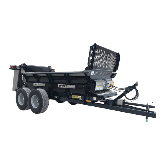
- Page 1 INSTRUCTION AND PARTS BOOK – REV. B2 HEAVY DUTY MANURE SPREADERS Model: VB235 DO NOT Operate This Spreader Until You Have Completely Read This Book! NEVER Repair or Clean This Spreader While PTO is Engaged! Manufactured in DORCHESTER, WI by MEYER’S EQUIPMENT...
- Page 2 MODEL SPECIFICATIONS Width of Box Inside 61” Overall Width 118” Length of Box Inside 178” Depth 36” Overall Length 26’3” Overall Height - Front 106” Ground Clearance 16-1/2” Capacity (Struck)* 235 ft3 Capacity (Heaped)* 390 ft3 App. Empty Weight (lbs.) 9,200 Loading Height 72”...
-
Page 3: Introduction
INTRODUCTION Congratulations on the purchase of your new Meyer’s Manure Spreader! With proper use and preventative maintenance, it will give you many years of trouble-free operation. • At the front of this manual is a Product Registration and Inspection Certificate. Be sure your dealer has completed this certificate and forwarded a copy to the manufacturer to validate the manufacturer’s warranty. -
Page 4: Table Of Contents
TABLE OF CONTENTS INTRODUCTION ..............................3 SAFETY SYMBOLS ............................. 6 SAFETY DECALS & LOCATIONS ........................7 MANURE SPREADER SAFETY ........................10 MANDATORY SAFETY SHUTDOWN PROCEDURE ..................11 PRESSURIZED HYDRAULIC FLUID AND EQUIPMENT SAFETY ..............12 PRE-OPERATION ............................. 13 GENERAL ................................. 13 TRACTOR HITCH AND PTO REQUIREMENTS ...................... - Page 5 REPLACEMENT PARTS ............................. 26 BOX PARTS, SHIELDS, & MISC..........................26 HYDRAULIC END GATE & RELATED PARTS ....................... 28 AXLE & RELATED PARTS, TANDEM AXLE ......................... 30 AXLE & RELATED PARTS, SINGLE AXLE ........................32 VERTICAL BEATERS, DRIVE TRAIN & RELATED ......................34 VERTICAL BEATER HEAD ASSEMBLY ........................
-
Page 6: Safety Symbols
SAFETY SYMBOLS A brief definition of signal words that may be used in this manual: DANGER : Indicates an imminently hazardous situation that, if not avoided, will result in serious injury or death. WARNING : Indicates a potentially hazardous situation that, if not avoided, could result in death or serious injury. -
Page 7: Safety Decals & Locations
SAFETY DECALS & LOCATIONS ** REFERENCE PAGES 8 & 9 FOR DECAL LETTERS AND PART #’S (BOTH SIDES) (BOTH SIDES) (BOTH SIDES) (BOTH SIDES) (BOTH SIDES) (BOTH SIDES) (BOTH SIDES) M o d e l V B 2 3 5 P a g e... - Page 8 DECAL E - #3006 DECAL A - #3004 DECAL B - #3003 DECAL F - #SW2000 DECAL C - #SW105 DECAL G - #SW2001 DECAL H - #SW700 DECAL D - #3011 P a g e M o d e l V B 2 3 5...
- Page 9 DECAL I - #3002 DECAL J - #VB107 DECAL L - #SW405 DECAL R1 – YELLOW REFLECTOR TAPE #PM17-5910 DECAL R2 – RED REFLECTOR TAPE DECAL K - #VB106 #PM17-5915 CAUTION IF ANY SAFETY SIGN BECOMES UNREADABLE FOR ANY REASON, THE SIGN MUST BE REPLACED WITH A NEW SIGN.
-
Page 10: Manure Spreader Safety
MANURE SPREADER SAFETY CAUTION THERE ARE INHERENT HAZARDS ASSOCIATED WITH THE OPERATION OF A MANURE SPREADER. FOR YOUR SAFETY: • Never Enter Spreader Box While In Operation For Any Reason. • Only Properly Instructed People Should Operate The Spreader. Do Not Allow Children Or Inexperienced Persons To Operate The Spreader. -
Page 11: Mandatory Safety Shutdown Procedure
MANDATORY SAFETY SHUTDOWN PROCEDURE BEFORE unclogging, cleaning, adjusting, lubricating or servicing the unit: 1. Disengage the tractor PTO. 2. Shut off the tractor engine, remove the ignition key and take it with you. 3. Wait for all movement to stop. 4. -
Page 12: Pressurized Hydraulic Fluid And Equipment Safety
PRESSURIZED HYDRAULIC FLUID AND EQUIPMENT SAFETY • Only adequately trained and qualified persons should work on hydraulic systems. You may be severely injured or killed by being crushed under a falling piece of equipment. Always have transport locks in place and frame sufficiently blocked when working on any implement. •... -
Page 13: Pre-Operation
PRE-OPERATION GENERAL Read the entire Owner’s Manual before attempting to operate this manure spreader. Before attempting any maintenance or repairs; always be sure all rotating parts have stopped and that the tractor is shut off. Disconnect the PTO, relieve all hydraulic pressure and disconnect hydraulic hoses. WARNING NEVER OPERATE SPREADER WITH ANY GUARDS OR SHIELDS REMOVED. -
Page 14: Tractor Towing Size Requirements
Spreader Gross Weight Empty Weight (9200 lbs) + Load Weight = Gross Weight Minimum Tractor Weight Spreader Gross Weight x (2/3) = Min Tractor Weight LOAD TYPE VB235 CAPACITY EXAMPLE Struck Level 235 ft A heaped load of pen packed manure:... -
Page 15: Open And Closed Center Hydraulic Systems
Open and Closed Center Hydraulic Systems • Most late model tractors use a Closed Center hydraulic system with a variable displacement pump which only pumps oil as required. This system is commonly CCLS (Closed Center Load Sensing), also known as PFC (Pressure and Flow Compensated). The ball valve on the spreader should be closed. •... -
Page 16: Safety Chain Use
Safety Chain Use A safety chain should be installed when traveling on public roads. The chain must be strong enough to hold the weight of the loaded spreader. If using a grab hook at the end(s) of the chain to secure the chain to itself, a hook latch must be installed. -
Page 17: Operation
OPERATION DANGER CAUTION NEVER ENTER THE SPREADER BOX FOR ANY DO NOT USE JACK EXCEPT WHEN SPREADER REASON WITHOUT FIRST DISCONNECTING IS EMPTY. JACK WILL NOT SUPPORT ADDED PTO SHAFT FROM TRACTOR. DO NOT ALLOW WEIGHT FROM LOAD. UNBALANCED WEIGHT MAY RESULT IN UNEXPECTED “TIP UP”... -
Page 18: Unloading
UNLOADING The rear beaters have been designed and tested to provide the best spread pattern for most liquids and semi- solid manure. However, the pattern will vary for each specific condition. The factors that contribute most to differing patterns will be moisture content and the amount and length of bedding material. For most typical conditions, the spread pattern should be uniform and about 30 ft wide or more. -
Page 19: Hydraulic Apron, Speed Control Options
Hydraulic Apron, Speed Control Options Standard Flow Control: The standard system utilizes the tractor’s flow control. This system requires that the tractor have an adjustable flow control lever or knob. There is no adjustable flow control valve on the spreader with this option. Manual Flow Control: The manual flow control option has an adjustable flow control valve on the spreader. -
Page 20: Maintenance, Adjustments, & Lubrication
MAINTENANCE, ADJUSTMENTS, & LUBRICATION WHEEL & TIRE MAINTENANCE WHEELS: Check after first hour of towing and periodically thereafter. The wheel studs should be torqued to 297 foot pounds in a crisscross pattern. TIRE PRESSURES: 425-65R Recommended Pressure: 65 PSI 1600R20 Recommended Pressure: 75 PSI 19L x 16.1 Recommended Pressure: 25 PSI 600/55 x 26.5 Recommended Pressure: 50 PSI Wheel Hub Lubrication... - Page 21 THIS PAGE INTENTIONALLY LEFT BLANK. M o d e l V B 2 3 5 21 | P a g e...
- Page 22 BOTH SIDES BOTH SIDES ILLUSTRATION SHOWS MODEL VB280 BOTH SIDES FRONT PTO DRIVESHAFT ASSEMBLY w/ CV JOINT REAR PTO DRIVESHAFT ASSEMBLY w/ OVER-RUNNING CLUTCH 22 | P a g e M o d e l V B 2 3 5...
-
Page 23: Adjustments
ADJUSTMENTS - INSPECT APRON TENSION DAILY!! - The apron chain is adjusted by (4) adjuster bolts located at the front of the box frame. Turn the nuts to pull the tensioners forward to remove all slack. Check that there is no sag at the front or rear of the spreader. -
Page 24: Cleaning And Storage
CLEANING AND STORAGE Before storing this spreader for an extended period of time, perform the following: 1. Allow the spreader to completely clean out the last load. 2. Thoroughly hose off all manure from the outside of the spreader and the inside of the box, particularly getting the end gate mechanism clean. - Page 25 THIS PAGE INTENTIONALLY LEFT BLANK. M o d e l V B 2 3 5 25 | P a g e...
-
Page 26: Replacement Parts
REPLACEMENT PARTS BOX PARTS, SHIELDS, & MISC. ILLUSTRATION SHOWS MODEL VB280 26 | P a g e M o d e l V B 2 3 5... - Page 27 BOX PARTS & MISC. PART NO. QTY. DESCRIPTION E00016 LATCH ASSEMBLY E01273 DOOR HINGE E30326 GAS SPRING w/ BALL STUDS E30804 ROCK GUARD ASSEMBLY E00003-40 BELTING BOLT BAR E00006 BELTING, 12” x 60-3/4” E00053-11 JACK ASSEMBLY, 8000 LB CAP, 190724 E00053-19 JACK ASSEMBLY, REF# DG590ZW, FOR Ø2.00 OD MOUNT E21650...
-
Page 28: Hydraulic End Gate & Related Parts
HYDRAULIC END GATE & RELATED PARTS PART NO. QTY. DESCRIPTION E31055 FRAME WELDMENT, METER GATE E31057L SLIDER TUBE WELDMENT, LH SIDE E31057R SLIDER TUBE WELDMENT, RH SIDE E00003-40 BELTING BAR E30770 BELTING, GATE BOTTOM, 7-1/2” x 62-3/8” E31053 MAIN PANEL, METER GATE E31074R GATE CHANNEL INSERT, POLY, RH w/ SENSOR HOLES E31074L... - Page 29 THIS PAGE INTENTIONALLY LEFT BLANK M o d e l V B 2 3 5 29 | P a g e...
-
Page 30: Axle & Related Parts, Tandem Axle
AXLE & RELATED PARTS, TANDEM AXLE REAR FRONT LONGER HALF OF ARM ASSEMBLY TOWARD FRONT 30 | P a g e M o d e l V B 2 3 5... - Page 31 AXLE & RELATED PARTS, TANDEM AXLE PART NO. QTY. DESCRIPTION E00120-01 ARM ASSEMBLY, STANDARD, 46” C-C E00120-49-2.75 ARM ASSEMBLY, OPTIONAL for OVERSIZED TIRES, 49” C-C E01693-COMP HUB ASSEMBLY, G60-8, COMPLETE E01693 HUB, G60-8 w/ CUPS & STUDS E01679 HUB CAP, G909912 E01685 COTTER PIN, G905942 E01683...
-
Page 32: Axle & Related Parts, Single Axle
AXLE & RELATED PARTS, SINGLE AXLE 32 | P a g e M o d e l V B 2 3 5... - Page 33 AXLE & RELATED PARTS, SINGLE AXLE PART NO. QTY. DESCRIPTION E00176-VB-COMP HUB ASSEMBLY, G873, COMPLETE E00176-VB HUB, G873 w/ CUPS & STUDS E00171-VB SPINDLE, STANDARD, Ø3-3/8” x 20-12”L, G286802L20.500C VB-00148 SPINDLE, FLOTATION, Ø3-3/8” x 23-3/4”L, G286802L23.750C E00172-VB SEAL, HUB, G946275 E00173-VB BEARING, INNER, G910398 (33275) E00174-VB...
-
Page 34: Vertical Beaters, Drive Train & Related
VERTICAL BEATERS, DRIVE TRAIN & RELATED ILLUSTRATION SHOWS MODEL VB280 34 | P a g e M o d e l V B 2 3 5... - Page 35 VERTICAL BEATERS, DRIVE TRAIN & RELATED PART NO. QTY. DESCRIPTION DRIVE SHAFT ASSEMBLY, Ø1-3/8 – 21 SPLINE, 1000 RPM 245-25785 (See Separate Listing) DRIVE SHAFT ASSEMBLY, Ø1-3/8 – 6 SPLINE, 540 RPM 245-27515 (See Separate Listing) DRIVESHAFT ASSEMBLY, REAR w/ CLUTCH, Ø1-3/4 – 6 SPLINE 242-25787 (See Separate Listing) VERTICAL BEATER HEAD ASSEMBLY (See Separate Listing)
-
Page 36: Vertical Beater Head Assembly
VERTICAL BEATER HEAD ASSEMBLY 36 | P a g e M o d e l V B 2 3 5... - Page 37 VERTICAL BEATER HEAD ASSEMBLY PART NO. QTY. DESCRIPTION 16025 GEAR BOX, SRT8, 1000 RPM OPTION (SEE SEPARATE LISTING) 16025-540 GEAR BOX, SRT8, 540 RPM OPTION (SEE SEPARATE LISTING) 15764 RIGHT PANEL 15765 LEFT PANEL 16028 CROSS BAR 16030 LEFT BEATER 16031 RIGHT BEATER 3768...
-
Page 38: Vertical Beater Gearbox
VERTICAL BEATER GEARBOX 38 | P a g e M o d e l V B 2 3 5... - Page 39 VERTICAL BEATER GEARBOX PART NO. QTY. DESCRIPTION 3426 CIRCLIP, E 40 9476 PINION, Z=13 3346 BEARING, 6308 7478 BEARING, 6309 9502 GEAR, Z=20, 1000 RPM OPTION 9501 GEAR, Z=16, 540 RPM OPTION 3427 CIRCLIP, E 45 9522 SHAFT 9524 SPACER 9926 O-RING, 2175 3302...
-
Page 40: Vertical Beater Lubrication Kit
VERTICAL BEATER LUBRICATION KIT 40 | P a g e M o d e l V B 2 3 5... - Page 41 VERTICAL BEATER LUBRICATION KIT PART NO. QTY. DESCRIPTION 16032 COPPER PLATED STEEL PIPE 9587 PIPE CLIP 9586 RIVET, Ø3.5X8 9578 FITTING 9579 COMPRESSION CONE 9583 TERMINAL, Ø1/8” GAS 9581 LUBRICATION BLOCK 3414 GREASE FITTING, MB10 12110 COMPLETE 90° TERMINAL M o d e l V B 2 3 5 41 | P a g e...
-
Page 42: Pto Drive Shaft Assembly, Front
PTO DRIVE SHAFT ASSEMBLY, FRONT Ø1-3/8 – 21 SPLINE (1000 RPM) or Ø1-3/8 – 6 SPLINE (540 RPM) PART NO. DESCRIPTION 1 3/8-21 1 3/8-6 E00471-10 Joint & Shaft Half Asm W/Guard, 93-25050 E00471-540 Joint & Shaft Half Asm W/Guard, 540 RPM Option E00476-11 Joint &... -
Page 43: Pto Drive Shaft Assembly W/ Clutch, Rear
PTO DRIVE SHAFT ASSEMBLY w/ CLUTCH, REAR PART NO. QTY. DESCRIPTION 93-25787 Joint & Shaft Half Asm. w/Guard 95-25787 Joint & Shaft Half Asm. 92-25787 Joint & Tube Half Asm w/Guard 94-25787 Joint & Tube Half Asm. 38-20044 Yoke & Clutch Hub Assembly (See Separate Listing) 03-15287 35EBL Cross Kit 99-25787... -
Page 44: Yoke & Clutch Hub Assembly
YOKE & CLUTCH HUB ASSEMBLY PART NO. QTY. DESCRIPTION 35301-1005 Yoke 23-15057 Wave Spring 38-30077 Overrunning Inner Hub 11-15081 Setscrew 12-11018 Ball, Ø.250 11-15136 Washer 24-15133 Retaining Ring 06-13492 Hub Clamp Assembly 80401-1000 Overrunning Hub 11-15134 Overrunning Key 23-15056 Leaf Spring 38-20044 Yoke &... -
Page 45: Automatic / Over-Running Clutch Assembly
AUTOMATIC / OVER-RUNNING CLUTCH ASSEMBLY PART NO. QTY. DESCRIPTION 11-15173 Bolt, M10-1.5 X 18 LG CL10.9 80461-1000 Housing 80661-1005 Disconnect Driver 11-15445 Drive Wedge 06-15572 Wedge Ring 23-15061 Spring 20-15157 Compression Plate 11-15407 O-Ring 24-15143 Retaining Ring 11-15288 O-Ring 24-15144 Retaining Ring 38-52105 Clutch Pack, Complete... -
Page 46: Apron & Related Parts, Standard 67P11 Chain
APRON & RELATED PARTS, STANDARD 67P11 CHAIN TIGHTENER KITS INCLUDE: WELDMENT, NYLON ROLLER, SHAFT WASHERS, COTTER PIN, NUTS, AND BOLTS. 46 | P a g e M o d e l V B 2 3 5... - Page 47 APRON & RELATED PARTS, STANDARD 67P11 CHAIN PART NO. QTY. DESCRIPTION E31110-235 APRON, ONE SIDE COMPLETE (41 SLATS / 242 LINKS) E02024-375 TIGHTENER WELDMENT, RH OUTER E02038-375 TIGHTENER KIT, COMPLETE, RH OUTER E02040 TIGHTENER WELDMENT, RH CENTER E02032 TIGHTENER KIT, COMPLETE, RH CENTER E02031 TIGHTENER WELDMENT, LH CENTER E02033...
-
Page 48: Apron Drive Gearbox
APRON DRIVE GEARBOX 48 | P a g e M o d e l V B 2 3 5... - Page 49 APRON DRIVE GEARBOX KEY PART NO. QTY. DESCRIPTION VB-00061-440 Gear Reducer, Complete RT350 14552 VB-00032-440 Housing 9975 VB-00033-440 14551 VB-00034-440 Circlip E 82 9918 VB-00035-440 Gear Z=49 9974 VB-00036-440 Bearing 6015 9982 VB-00037-440 Circlip I 115 9984 VB-00038-440 Pinion Z=12 8670-5 VB-00039 Key 12 x 8 x 30...
-
Page 50: Apron Lube Bank
APRON LUBE BANK PART NO. QTY. DESCRIPTION 60102 GREAZE ZERK, 1/8” NPT 66270 COUPLING, 1/8” NPT 66406 PIPE NIPPLE, 1/8” NPT x 4”L SCH40 BLK VB-00031 BCMP 90° ELBOW, 3/16”T x 1/8”NPT, 440455-131280 TUBING, COPPER, Ø3/16” (Order by the Foot) 50 | P a g e M o d e l V B 2 3 5... -
Page 51: Highway Lighting & Wiring
HIGHWAY LIGHTING & WIRING VIEWED FROM REAR WIRE COLORS - FUNCTIONS WHITE- GROUND BROWN- TAIL / RUNNING LIGHTS RED- STOP LAMPS GREEN- RIGHT TURN & HAZARD YELLOW- LEFT TURN & HAZARD PART NO. QTY. DESCRIPTION E30534 LIGHT MOUNT BEAM, 19-1/2”L E30531R LIGHT BRACKET ADAPTER MOUNT, RH E30531L... -
Page 52: Gate Height Indicator System
GATE HEIGHT INDICATOR SYSTEM PART NO. QTY. DESCRIPTION E31103-RM-4C PCB RELAY MODULE, COMPLETE E31070 LED LIGHT, RED/GREEN, S22DLGRXPQ E31083B PROXIMITY SENSOR, PNK-AP-3H (PNP / NO) E31115-BB WIRING HARNESS B, PCB to LEDs + Solenoid E31115-AB WIRING HARNESS A, PCB to Sensors + Power 52 | P a g e M o d e l V B 2 3 5... - Page 53 THIS PAGE INTENTIONALLY LEFT BLANK M o d e l V B 2 3 5 53 | P a g e...
-
Page 54: Hydraulic System Parts, Metering Gate
HYDRAULIC SYSTEM PARTS, METERING GATE 54 | P a g e M o d e l V B 2 3 5... - Page 55 HYDRAULIC SYSTEM PARTS, METERING GATE PART NO. QTY. DESCRIPTION E00079 HOSE CLAMP, PLASTIC, Ø5/8” 2703-LN-08 BULKHEAD TEE, M-JIC x3 E01591 QUICK COUPLER, 8010-4P, 1/2" NPT HYDRAULIC HOSE, 6M3K-8FJX-8MP, 120” HYDRAULIC HOSE, 6M3K-8FJX-8FJX, 222” HYDRAULIC HOSE, 6M3K-8FJX-8FJX90S, 37” HYDRAULIC HOSE, 6M3K-8FJX-8FJX90S, 14” 2700-LN-08 BULKHEAD UNION 6801-8-8...
-
Page 56: Hydraulic System Parts, Apron Drive, Standard Flow Control
HYDRAULIC SYSTEM PARTS, APRON DRIVE, STANDARD FLOW CONTROL 56 | P a g e M o d e l V B 2 3 5... - Page 57 HYDRAULIC SYSTEM PARTS, APRON DRIVE, STANDARD FLOW CONTROL PART NO. QTY. DESCRIPTION E30010 VALVE, STANDARD FLOW CONTROL, BG-514-12SAE 304-C-8 CAP, 08FJIC E00509-440 HYDRAULIC MOTOR w/ RELIEF, 255160A1912ACAAA 6600-8-8-8 ADAPTER BRANCH TEE, 08MJIC-08MJIC-08FJS 6801-8-10 ADAPTER, 90° ELBOW, 08MJIC-10MORB 6801-8-12 ADAPTER, 90° ELBOW, 08MJIC-12MORB 8010-4P QUICK COUPLER, MALE TIP, ISO 5675, ½”...
-
Page 58: Hydraulic System Parts, Apron Drive, Manual Flow Control
HYDRAULIC SYSTEM PARTS, APRON DRIVE, MANUAL FLOW CONTROL OPEN CENTER SYSTEMS WITH A FIXED DISPLACEMENT PUMP, BALL VALVE SHOULD BE OPEN. CLOSED CENTER SYSTEMS WITH A VARIABLE DISPLACEMENT PUMP, BALL VALVE MAY BE CLOSED. SEE PAGE 15 FOR DETAILS. 58 | P a g e M o d e l V B 2 3 5... - Page 59 HYDRAULIC SYSTEM PARTS, APRON DRIVE, MANUAL FLOW CONTROL PART NO. QTY. DESCRIPTION E00486-00 VALVE, MANUAL FLOW CONTROL, RD-1910-16 6400-8-10 ADAPTER, 10MORB-08MJIC 6801-8-10 ADAPTER, 90° ELBOW, 10MORB-08MJIC 2700-LN-8-8 BULKHEAD, STRAIGHT, 08MJIC-08MJIC 6403-NWO-10-08 ADAPTER, 10MORB-08MORB E00497-00 BALL VALVE, #8 SAE, 72-903 6400-8-8 ADAPTER, 08MORB-08MJIC 6600-8-8-8 ADAPTER BRANCH TEE, 08MJIC-08MJIC-08FJS...
-
Page 60: Hydraulic System Parts, Apron Drive, Electric Flow Control
HYDRAULIC SYSTEM PARTS, APRON DRIVE, ELECTRIC FLOW CONTROL OPEN CENTER SYSTEMS WITH A FIXED DISPLACEMENT PUMP, BALL VALVE SHOULD BE OPEN. CLOSED CENTER SYSTEMS WITH A VARIABLE DISPLACEMENT PUMP, BALL VALVE MAY BE CLOSED. SEE PAGE 15 FOR DETAILS. 60 | P a g e M o d e l V B 2 3 5... - Page 61 HYDRAULIC SYSTEM PARTS, APRON DRIVE, ELECTRIC FLOW CONTROL PART NO. QTY. DESCRIPTION E00500 VALVE, ELECTRIC FLOW CONTROL, EFC12-15-12 E00502 CONTROL BOX, ELECTRIC FLOW CONTROL, EC-12-01 E00509-440 HYDRAULIC MOTOR w/ RELIEF, 255160A1912ACAAA 6400-8-8 ADAPTER, 08MORB-08MJIC 6403-NWO-12-08 ADAPTER, 12MORB-08MORB 6600-8-8-8 ADAPTER BRANCH TEE, 08MJIC-08MJIC-08FJS 6801-8-10 ADAPTER, 90°...
-
Page 62: Limited Warranty Statement
LIMITED WARRANTY STATEMENT Meyer’s Equipment Mfg. Corp. warrants each new Meyer’s E.M.C. product to be free from defects in material and workmanship. This warranty is applicable only for the normal service life expectancy of the product or components, not to exceed 12 consecutive months from the date of delivery of the new Meyer’s E.M.C.
Need help?
Do you have a question about the VB235 and is the answer not in the manual?
Questions and answers