
Summary of Contents for NOYAFA NF-826
- Page 1 Your excellent helper in NF-826 measuring instruments. UNDERGROUND WIRE LOCATOR UNDERGROUND WIRE LOCATOR USER MANUAL USER MANUAL Your excellent helper in measuring instruments VER: V1...
-
Page 2: Table Of Contents
1. Overview ....................01 4. Other functions ..................25 1.1 Product introduction ................02 4.1 Voltmeter function of the transmitter ............25 1.2 Characteristics of NF-826 Cable Locator ...........03 4.2 Flashlight function ..................25 ..............04 1.3 Names and functions of parts 4.3 Backlight function ..................25 1.3.1 Sketch of transmitter... -
Page 3: Overview
Please ensure that the instrument and the test lead in use are intact. The instrument should not be used unless all the functions of the instrument are well prepared for Now, with this NF-826 Cable Locator developed by our company to effectively assist work. -
Page 4: Names And Functions Of Parts
1.2 Characteristics of Cable Locator NF-826 1.3 Names and Functions of Parts ♦Detecting cables, electrical lines, water/gas supply pipelines buried in wall or earth; ♦1.3.1 Sketch of transmitter ♦Detecting interruptions and short circuit in cables and electrical lines buried in wall ①. -
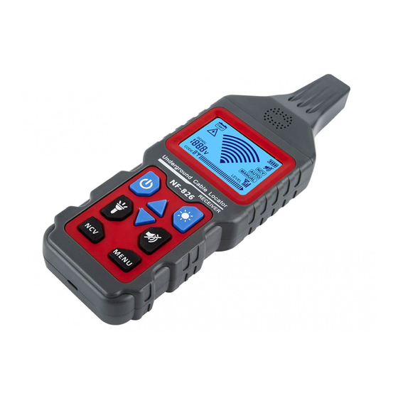
Page 5: Sketch Of Receiver
1.3.3 Sketch of receiver 2. CARRYING OUT MEASUREMENT ♦ ① Flashlight. ② Probehead 2.1 Measurement Precautions ③ LCD screen ④ Power on-off key WARNING ⑤ Key for adjusting sensitivity up under manual mode. 1.As the connection of the transmitter with the mains supply may generate circuit current ⑥... -
Page 6: Examples Of Typical Application
2.3 Examples of Typical Application In this example, please take a piece of a shielded cable with a cross sectional area of 1.5mm² Provisionally install 5m of this cable along the wall with nail clips at eye level as surface mounting. Make sure that the wall is accessible from both sides. -
Page 7: Details Of Application
3.1.1 Locating of line interruptions 3. DETAILS OF APPLICATION Preconditions: ※ The circuit must be dead. 3.1 In open circuit ※ All lines which are not required must be connected to the auxiliary ground in ※ Detecting line interruptions in wall or floor; accordance with Fig. -
Page 8: Locating And Tracing Of Lines And Sockets
3.1.2 Locating and tracing of lines and sockets 3.1.3 Detect the narrow (blocked) part of the laid non-metallic pipeline Preconditions: ※ The circuit must be dead. Preconditions: ※ The pipeline must be made of non-condactive materials (such as plastic); ※ Neutral line and protective ground wire must be connected and fully operational. -
Page 9: Detect The Laid Metal Tap Water Pipe And Metal Heating Pipe
3.1.4 Detect the laid metal tap water pipe and metal heating pipe 3.1.5 Locating of line interruptions using two transmitters Preconditions: When locating a line interruption using one transmitter to feed from one conductor end, the location of interruptions may not be precisely located in case of bad conditions due to a field disturbance. The ※... -
Page 10: Error Detection For An Electrical Floor Heating
3.1.6 Error detection for an electrical floor heating 3.1.7 Track an underground circuit Preconditions: Preconditions: ※ The current circuit must not be live. ※ The circuit must not be charged; All lines not being used must be connected to the auxiliary ground as shown in Connect the transmitter in a way shown in Fig.3-1-7;... -
Page 11: Detect The Power Supply Circuit On The Same Floor
3.1.8 Detect the power supply circuit on the same floor 3.2 Dual-pole Applications When detecting the power supply circuit on the same floor, please take the following 3.2.1 Search for the fuses steps: In a building with multiple residences , use the L and N ports on the socket of any 1).Turn off the main switch in the distribution box of this floor;... -
Page 12: Search For Short Circuit In The Circuit
3.2.2 Search for short circuit in the circuit 3.2.3 Applications in closed circuits Preconditions: It can be applied to charged circuits and uncharged circuits: ※ The circuit must be uncharged; In uncharged circuits, the transmitter only sends encoding signals to the circuit to be ※... -
Page 13: Classify Or Determine The Laid Circuit
3.2.4 Classify or determine the laid circuit 3.2.5 Detect circuits laid relatively deep Preconditions: In dual-pole applications, if the loop line is made of core wires in cables with multiple ※ The circuit must be uncharged; core wires (such as NYM 3*1.5mm²), the depth of detection will be greatly limited. ※... -
Page 14: Method To Increase The Effective Radius Of Detecting Charged Circuits
3.3 Method to increase the effective radius of detecting charged 3.4 Identify voltage in the grid and search for breakages in the circuits circuit When the transmitter is directly connected to the phase line and neutral line, the signals Preconditions: are conducted on two parallel circuits (as shown in Fig.3-3-1), so the twisting of circuits ※... -
Page 15: Other Functions
4. OTHER FUNCTIONS 5. TECHNICAL PARAMETERS 4.1 Voltmeter function of the transmitter Output signal 125kHz If the transmitter is connected to a charged circuit and the external voltage is higher than DC 12~400V ±2.5%; External voltage 12V, the lower left part of the monitor of transmitter shows current value of voltage, and identification range AC 12~400V(50~60Hz) ±2.5% standard symbols are used to distinguish AC and DC circuits (see... -
Page 16: Repair And Maintenance
6. REPAIR AND MAINTENANCE 6.2 Checking of the fuse of the transmitter The fuse of the transmitter can prevent the transmitter from being damaged by overload or wrong operations. If the fuse in the transmitter has already been melted down, the 1.If the detector is suspected of malfunctioning , please confirm that the electrical transmitter can only transmit weak signals.
Need help?
Do you have a question about the NF-826 and is the answer not in the manual?
Questions and answers