Table of Contents
Advertisement
Quick Links
Advertisement
Table of Contents
Troubleshooting

Summary of Contents for SonoSite MicroMaxx
- Page 1 MicroMaxx™ Ultrasound System Service Manual...
- Page 2 Non-SonoSite product names may be trademarks or registered trademarks of their respective owners. SonoSite products may be covered by one or more of the following U.S. patents: 4454884, 4462408, 4469106, 4474184, 4475376, 4515017, 4534357, 4542653, 4543960, 4552607, 4561807, 4566035, 4567895, 4581636, 4591355, 4603702, 4607642, 4644795, 4670339, 4773140, 4817618, 4883059,...
-
Page 3: Table Of Contents
Contents Chapter 1: Introduction Audience ........................... 1 Conventions Used in This Service Manual ............1 Product Upgrades and Updates ................1 Customer Comments ....................1 About the System ......................2 About the System Software ..................3 Software Licensing ......................3 Chapter 2: Safety Electrical Safety ...................... - Page 4 OB Calculations Authors ..................33 OB Custom Measurements ................34 OB Custom Tables ....................35 Presets ........................36 System Information ...................37 Touchpad ........................38 Accessories ........................38 Preparing the System for Operation ..............38 Installing and Removing the Battery ............38 Installing and Removing the CompactFlash Card ........39 Using AC Power/Charging Battery ...............40 Connecting and Removing the Transducer ..........41 Turning System On/Off ..................41...
- Page 5 Pulsed Wave (PW) Doppler Imaging ............73 Image Quality Verification Test/Livescan ...........73 Image Review ......................73 Printer ........................73 Battery Charging ....................73 Video Output .......................74 Returning Products to SonoSite ................74 Contacting SonoSite Technical Support ............74 Shipping Instructions ..................74 Appendix A: Parts List Replacement Parts List ....................75 Display ........................75 Control Panel .......................77...
-
Page 7: Chapter 1: Introduction
Chapter 1: Introduction Before servicing the MicroMaxx ultrasound system, please read the information in this manual. This text applies only to the SonoSite MicroMaxx ultrasound system product manufactured after June 1, 2005. Please find service information about products manufactured before June 1, 2005 in C1.51 Ultrasound System Service Manual (P00715), C1.75 Ultrasound System Service Manual (P01118), C1.9 PLUS Ultrasound System Service Manual (P02287), C1.99 PLUS... -
Page 8: About The System
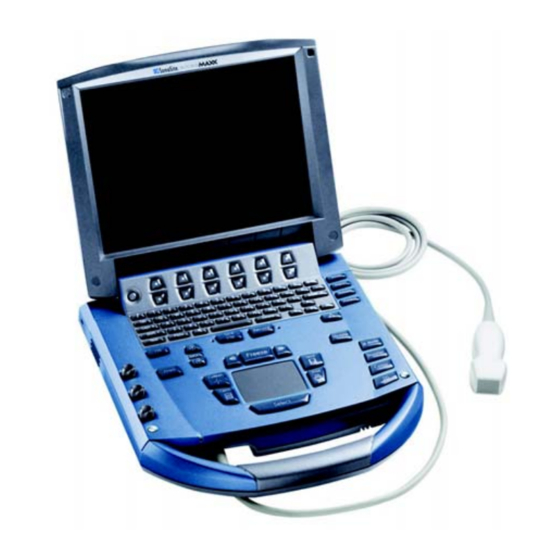
The ultrasound system has multiple configurations and feature sets. All are described in this service manual but not every option may apply to your system. System features are dependent on your system configuration, transducer, and exam type. Figure 1.1 MicroMaxx System Front View Table 1.1: MicroMaxx System Front Features Number... -
Page 9: About The System Software
“grace period. ” The grace period is variable. When you first install your software, your SonoSite system prompts you for a license key. If you have not yet obtained a valid license key, you can elect to use the software as long as the grace period time has not been fully consumed. - Page 10 Chapter 1: Introduction...
-
Page 11: Chapter 2: Safety
Do not connect these products to AC mains power when using the system to scan or diagnose a patient/subject. Contact SonoSite or your local representative for a list of the commercial grade peripherals available from or recommended by SonoSite. -
Page 12: Equipment Safety
Do not use the system if an error message appears on the image display: note the error code; call SonoSite or your local representative; turn off the system by pressing and holding the power key until the system powers down. -
Page 13: Battery Safety
SonoSite or your local representative. Store the battery between -20°C (-4°F) and 60°C (140°F). Use only SonoSite batteries. Do not use or charge the battery with non-SonoSite equipment. Only charge the battery with the system. Chapter 2: Safety... -
Page 14: Biological Safety
.3dB/cm/MHz. Some SonoSite transducers are approved for intraoperative applications if a market-cleared sheath is used. Labeling Symbols Labeling symbols for SonoSite products can be found in the user guide for each product. Chapter 2: Safety... -
Page 15: Chapter 3: System Overview
Chapter 3: System Overview System Overview The SonoSite High-Resolution Ultrasound System (MicroMaxx) is a full featured, general purpose, software controlled, diagnostic ultrasound system used to acquire and display high-resolution, real-time ultrasound data in 2D, M-Mode, Pulsed Wave (PW) Doppler, Continuous Wave (CW) Doppler, Color Power Doppler, and Velocity Color Doppler or in a combination of these modes. -
Page 16: Theory Of Operation
Theory of Operation The SonoSite High-Resolution Ultrasound System (MicroMaxx) has seven (7) major functional groups: • Transducer • Acquisition Subsystem • Processing Subsystem • Display Subsystem • Control Subsystem • User Interface Subsystem • Power Subsystem Figure 3.1 is a system block diagram that shows the relationship of the functional groups. -
Page 17: Description Of Operating Modes
The Control Subsystem consists of the central processing unit, program and video memory, permanent image storage and retrieval memory, external communication interface ports, and connection to the user interface keys. The control software includes the acoustic power and intensity software subsystem, power group monitors, and a beamformer monitor. - Page 18 Continuous CW provides a real-time representation of blood flow and is displayed as a Wave (CW) velocity-versus-time sweeping output. Velocity (or frequency) is presented as the vertical Doppler axis with time along the horizontal axis. The magnitude of the detected signal is represented as different gray scale values.
- Page 19 Peak & mean Back End Temporal Baseline Display Compress Averaging shift interpolate 128/192/256/384 128 samples samples per line @ 50/100/200 Hz Wall Post Resample Window gain filter 128 tap FIR 128 IQ pairs 128 samples RF (PW) or Quadrature @ 1 kHz @ 1 kHz basband input (CW) Audio Output...
-
Page 20: Velocity Color Doppler (Vcd)
Magnitude This module combines real and imaginary components to estimate magnitude spectrum. Estimation The magnitude of Doppler spectrum is calculated using “cordic approximation”, which is done by estimating the complex magnitude by successive approximation. The vectors are reflected into the first quadrant by taking the absolute value, then rotating them sequentially by halved degrees. -
Page 21: Additional System Feature Performances
Additional System Feature Performances Broadband Imaging This ultrasound acquisition system uses high resolution uses broadband technology in the transmit pulsers, transducer, and receivers. The receive path can capture and process signals over a wide spectrum, from below 2.0 MHz to beyond 10 MHz. For each application, the transmit pulse is designed to produce an appropriate bandwidth. -
Page 22: Ecg Module
ECG Module The ECG module allows a representation of the heart electrical activity to be displayed in real time with ultrasound images acquired and displayed on the System video display. The ECG module interfaces to the patient through three (3) ECG leads: Right Arm ECG lead (RA), Left Arm ECG lead (LA), and Left Leg ECG lead (LL). -
Page 23: Dicom
Low Pass Filter The low pass filter block removes the high frequency component from the received ECG signal. It is used to limit the signal to the frequency range of interest and provide rejection of 50/60 Hz signal content. Power Supplies The power supply block receives voltage from the system power supply. -
Page 24: Imaging Modes
Quick Reference Guide SiteLink Image Manager 3.0 SonoCalc IMT System User Guide Triple Transducer Connect Ultrasound gel Cables See the MicroMaxx Ultrasound System User Guide, MDS User Guide, and the MDS Lite User Guide for information on cables. Chapter 3: System Overview... -
Page 25: Peripherals
Peripherals See the manufacturer’s specifications for the following peripherals. Medical Grade Black-and-white printer Recommended sources for printer paper: Contact Sony at 1-800-686-7669 or www.sony.com/professional to order supplies or to obtain the name and number of the local distributor. Color printer Video cassette recorder Non-Medical Grade Kensington Security Cable... -
Page 26: Electromechanical Safety Standards
CISPR11:2004, International Electrotechnical Commission, International Special Committee on Radio Interference. Industrial, Scientific, and Medical (ISM) Radio-Frequency Equipment Electromagnetic Disturbance Characteristics-Limits and Methods of Measurement. The Classification for the SonoSite system, SiteStand, accessories, and peripherals when configured together is: Group 1, Class A. Airborne Equipment Standards RTCA/DO160D:1997, Radio Technical Commission for Aeronautics, Environmental Conditions and Test Procedures for Airborne Equipment, Section 21.0 Emission of Radio Frequency Energy, Category B. -
Page 27: Chapter 4: Setup And Operation
Chapter 4: Setup and Operation System Controls 12 13 Figure 4.1 System Controls Table 4.1: System Controls Number System Control Description Power Turns system on and off. Alphanumeric Use to enter text and numbers. Annotation Text Turns the keyboard on and off for text entry. Picto Turns the pictographs/pictograph marker on and off. - Page 28 Table 4.1: System Controls (Continued) Number System Control Description Near Adjusts the gain applied to the near field of the image. Adjusts the gain applied to the far field of the image. Gain Adjusts the overall gain applied to the entire image. AC power A steady green light indicates AC power is connected.
-
Page 29: System Components
Turns CPD/Color on and off. Turns 2D on. System Components The SonoSite system components are identified in “About the System” on page Setup System setup is used to customize the system. Press the Setup key to access and set up the following system... -
Page 30: Setup Security Settings
SonoSite provides a comprehensive set of tools on the system that allows its customers to meet the applicable security requirements listed in the HIPAA standard. SonoSite's customers are ultimately responsible for ensuring the security and protection of all electronic protected health information collected, stored, reviewed, and transmitted on the system. - Page 31 User Login Setting In the User Login list, select On or Off. • Selecting On restricts access to the system and requires the user to enter a user name and password. • Selecting Off allows access to the system and does not require the user to enter a user name and password.
- Page 32 Export or Import User Accounts Note: Export and import are used to configure multiple systems and to back up user account information. Export User Account Insert the CompactFlash card in the back slot of the system. See “Installing and Removing the CompactFlash Card” on page Press the Setup key.
- Page 33 Export Event Log Note: The Event log and the DICOM network log have the same filename (log.txt). When you export either one to the same CompactFlash card, it will overwrite the existing log.txt file. Insert the CompactFlash card in the back slot of the system. Select Log and then Export from the on-screen menu.
-
Page 34: Audio And Battery
Audio and Battery Figure 9 Setup Screen: Audio, Battery Key Click Press the Setup key. Select Audio, Battery. In the Key click list, select On or Off. Beep Alert Press the Setup key. Select Audio, Battery. In the Beep alert list, select On or Off. Sleep Delay Press the Setup key. -
Page 35: Connectivity
Note: If PC is selected, the system allows report data to be sent as ASCII text from the system to a PC. Special third party software must be on the PC to acquire, view, or format the data into a report. Check the compatibility of your software with SonoSite technical support. -
Page 36: Date And Time
Ethernet Setup Press the Setup key. Select Connectivity. Select Ethernet Setup. Enter information in the following fields: (see DICOM chapter for definition of terms) • Host Name • IP Address • Subnet Mask • Default Gateway • Alternate Gateway In the Network Speed list, select from the list. Select Save. -
Page 37: Delta Key And F Keys
Delta Key and F Keys Figure 12 Setup Screen: Delta Key, F Keys Delta Key Press the Setup key. Select Delta Key, F Keys. Select desired functionality for the Delta key. The Delta key will now control this function. F Keys Press the Setup key. -
Page 38: Imt Calculations
System Status Press the Setup key. Select Display Information. Select the desired check boxes to display the system status on the screen. Reset Select Reset from the on-screen menu to return settings for this setup page to factory default. IMT Calculations Figure 14 Setup Screen: IMT Calculations IMT Calculations Press the Setup key. -
Page 39: Ob Calculations Authors
OB Calculations Authors Figure 15 Setup Screen: OB Calculations Gestational Age Press the Setup key. Growth Analysis Select OB Calculations. In Gestational Age or Growth Analysis lists, select the desired OB authors. Selecting an author places the measurement on the calculation menu and selecting None removes the measurement from the calculation menu. -
Page 40: Ob Custom Measurements
OB Custom Measurements Figure 16 Setup Screen: OB Custom Measurements OB Custom Press the Setup key. Measurements Select OB Custom Meas. Select New. In the Name field, enter a unique name. In the Type list, select the desired measurement type. Select Save. -
Page 41: Ob Custom Tables
OB Custom Tables Figure 17 Setup Screen: OB Custom Table Age Table Measurements: The system provides gestational age measurements by selected authors for the age table measurements listed in Table 4.2. Growth Analysis Table Measurements: The system provides growth graphs or curves for the growth table measurements listed in Table 4.2. -
Page 42: Presets
Edit OB Custom Tables Press the Setup key. Select OB Custom Meas. or OB Calculations. Select Tables... from the on-screen menu. Select the desired custom OB table. Select Edit and enter data and then select Save from the on-screen menu. Delete OB Custom Tables 1 Press the Setup key. -
Page 43: System Information
Save Key Press the Setup key. Select Presets. In the Save key list, select Image Only or Image/Calcs to designate the function of the Save key. • Selecting Image Only allows the Save key to save the image to the CompactFlash card. -
Page 44: Touchpad
Note: The arrow keys control much of the same functionality as the touchpad. Accessories For information about accessories and other SonoSite products, refer to the user guide for each product. Preparing the System for Operation Installing and Removing the Battery Caution: Use only the specified SonoSite battery pack. -
Page 45: Installing And Removing The Compactflash Card
Installing and Removing the CompactFlash Card Images and clips are saved to a CompactFlash card and are organized in a patient list. The images and clips in the patient list are organized alphabetically by the patient name and ID. Images and clips are archived from the ultrasound system to a PC using a USB, Ethernet connection, or CompactFlash card. -
Page 46: Using Ac Power/Charging Battery
Using AC Power/Charging Battery The battery charges when the system is connected to the AC power supply. If the system is off or in the sleep state (display off ), a completely discharged battery will fully charge in 2.5 to 3.5 hours. If the system is on and in the freeze state, a completely discharged battery will fully charge in 5 to 6 hours. -
Page 47: Connecting And Removing The Transducer
Caution: Do not use the system if an error message appears on the display. Note the error code and turn off the system. Call SonoSite or your local representative. Turn System Locate the Power key on the top left side of the system. See Figure 4.1 on page... -
Page 48: Upgrading The System And Transducer Software
Remove any transducer or Triple Transducer Connect from the system. System Connect the system directly to the power supply or through the MDS/mini-dock. See the Software SonoSite accessories user guide. Insert the CompactFlash card into the back slot. The system displays the following message: Figure 4.3 Upgrade System Software Select Yes to accept or No to cancel the upgrade. - Page 49 Figure 4.5 System Software Step 1 Restart Select Restart. After restart, there is a short delay before the system goes into the upgrade process. Do not turn the system off. The system displays the following message: Figure 4.6 System Software Installation When the upgrade is completed, the system displays the following message: Figure 4.7 System Software Step 2 Restart Select Restart.
- Page 50 Note: If you are upgrading a system and one or more transducers, it is recommended to upgrade all items before calling SonoSite Technical Support for your license keys. To postpone obtaining a license key, press Cancel from the on-screen menu.
- Page 51 Figure 4.10 Upgrade Transducer Software Select Upgrade to accept or Cancel to cancel the upgrade. When you accept the transducer software upgrade, the system loads the new software and displays the following message: Figure 4.11 Transducer Software Loading When the upgrade is completed, the system displays the following message. Figure 4.12 Transducer Software Installation Select Restart.
-
Page 52: Upgrading Triple Transducer Connect (Ttc)
Cancel from the on-screen menu. Upgrading Triple Transducer Connect (TTC) Upgrade TTC If the TTC requires an upgrade for the MicroMaxx system, the following message is displayed: “Do you want to upgrade the Triple Transducer Connect now?” If this message is displayed, perform the upgrade. -
Page 53: Installing A License Key
If the software is not yet licensed, the license update screen displays. The license update screen displays the following information: how to contact SonoSite, the required information to obtain the license key, and the grace period (time remaining) on your system. -
Page 54: To Display The System Information Screen
To Display the System Information Screen Display System Press the Setup key. Information Select System Information from the on-screen menu. Screen The system information screen displays the following information: Product, Modes, Previous License Update, Boot Version, ARM Version, DSP Version, PCBA Serial Number, PLD, CPLD Version, SH Database Version, and SH Serial Number. -
Page 55: Chapter 5: Cleaning And Disinfecting
For information about a specific product, call the product manufacturer. Recommended Disinfectants For a list of disinfectants recommended for use on the system and transducers, see the MicroMaxx Ultrasound System User Guide. Chapter 5: Cleaning and Disinfecting... - Page 56 Chapter 5: Cleaning and Disinfecting...
-
Page 57: Chapter 6: Troubleshooting
If you encounter difficulty with the system, use the information in this chapter to help correct the problem. If the problem is not covered here, contact SonoSite technical support at the following numbers or addresses: Technical Support (USA, Canada) -
Page 58: Periodic Maintenance
System and Subsystem Diagnosis This section covers basic diagnostic and troubleshooting procedures you may follow if the system does not operate properly. To diagnose system failures, consult the referenced diagnostic figures that follow or the SonoSite Technical Support department. Table 6.2: Troubleshooting Subassemblies and Diagnostic Figures... -
Page 59: Test Equipment
• If the assert condition remains, corrective action must be taken, usually replacement of the main PCBA is required. Contact SonoSite Technical Support for assistance and to obtain repair parts. If the Power button is not functional, all sources of power must be removed to allow the system to power down i.e., disconnect AC power and remove the battery. -
Page 60: Troubleshooting Flow Diagrams
Troubleshooting Flow Diagrams Display Figure 6.2 Display Flow Diagram Chapter 6: Troubleshooting... -
Page 61: Control Panel
Control Panel Figure 6.3 Control Panel Flow Diagram Chapter 6: Troubleshooting... -
Page 62: System
System Figure 6.4 System Flow Diagram Chapter 6: Troubleshooting... -
Page 63: Battery
Battery Figure 6.5 Battery Flow Diagram Chapter 6: Troubleshooting... -
Page 64: Dicom
Setting selected Image settings. E.g. Color (RGB) or failed Grayscale (Monochrome) DICOM network TDNETWORK_OPEN_FAILURE Device does not Verify that MicroMaxx AE Title or IP address communication recognize has been correctly configured on the failed MicroMaxx, rejects Printer/Archiver. association Note: Some devices require that the Imaging modality (MicroMaxx) be recognized in order to accept images. -
Page 65: Chapter 7: Replacement Procedures
Display Replacement Note: Consult Chapter 6, “Troubleshooting” before making any repairs. Required Parts Service Assembly, Display, MicroMaxx (P05463) Required Tools • #1 Phillips screwdriver • Torque screwdriver, 2.0–10.0 inch pounds (0.23–1.1 newton meter) • 8 mm nut driver • An anti-static mat •... - Page 66 Screws (2) Figure 7.2 System Bottom Turn the system over, fully open the display, and lift off the Control Panel per Figure Figure 7.3 Control Panel Removal Disconnect the two connectors from the display to the Main PCBA per Figure Chapter 7: Replacement Procedures...
-
Page 67: Display Replacement
Connectors (2) Figure 7.4 Display Connectors Remove the four screws from the Display Hinges per Figure 7.5. Screws (4) Figure 7.5 Display Screws Display Replacement Display Set the new display in place. Replacement Install the four screws that hold the Display in place. Torque the screws to 5.5 inch pounds. Connect the two connectors that connect the Display to the Main PCBA. -
Page 68: Test The Display
Control Panel Subassembly Replacement Required Parts • P05462 Service Assembly, Control Panel MicroMaxx, English or • P05464 Service Assembly, Control Panel MicroMaxx, English, International, or • P05465 Service Assembly, Control Panel MicroMaxx, French, or • P05466 Service Assembly, Control Panel MicroMaxx, German, or •... -
Page 69: Main System Disassembly For Repair And/Or Replacement
Note: Replacing the enclosure bottom requires printing a new label for the product. This must be printed prior to shipping the enclosure bottom. You will be required to provide the information to print this label. • Nest Frame Assembly, MicroMaxx (order these parts individually) • P00364 Connector, Interposer •... - Page 70 Screws (4) Figure 7.6 Bottom Screws Turn the system over and remove the top enclosure from the main PCBA. This exposes all of the replaceable parts for the main system per Figure 7.7. Main PCBA Nest frame assembly Power supply TGC assembly Speaker Speaker...
- Page 71 Speaker Replacement Speaker Press on the connector release and pull the connector out of the receptacle. Replacement Gently pry off the retaining clip with a flat bladed pry tool. See Figure 7.8. Connector Retaining clip Figure 7.8 Speaker Replacement Power Supply Power Supply Gently pry the shield from the power supply and set it aside.
- Page 72 Screws (7) Figure 7.10 Power Supply Screws Chapter 7: Replacement Procedures...
- Page 73 TGC PCBA TGC PCBA Remove the TGC knobs identified in Figure 7.11. TGC knobs (3) Figure 7.11 TGC Knobs Remove the flex cable from the TGC PCB by lifting on the flex release tab. See Figure 7.12. Remove the flex cable from the Main PCBA by lifting gently on the flex release tab. Remove the two screws holding the TGC PCBA in place.
- Page 74 Main PCBA Main PCBA Remove the 3 screws holding the Main PCBA in place per Figure 7.13. Remove the 4 shoulder bolts holding the transducer nest frame assembly in place. As you remove the nest frame assembly from the PCBA tilt the PCBA and enclosure to almost vertical to avoid spilling the Interposer Connectors from the Assembly.
-
Page 75: Chapter 8: Performance Testing
• Verify that all controls operate smoothly over their full range and that the system responds properly. • To obtain 2D images, SonoSite recommends using the RMI 413A Soft Tissue Phantom or the RMI 403 GS Multipurpose Phantom. Any equivalent Phantom is acceptable. -
Page 76: Testing 2D Performance
Press the Caliper key. The caliper appears on the image display. The screen menu indicates Cal 1, Cal 2, and Ellipse. (If the caliper line setup is on, then a dotted line connects the two calipers. See the MicroMaxx Ultrasound System User Guide, if necessary.) The Cal 1 caliper is active by default. -
Page 77: Lateral Measurement Accuracy
Lateral Measurement Accuracy Set up Lateral Perform steps 1 through 7 in Section Measurement Accuracy Test Lateral Measure the distance, center to center, of any two pins that are 4-10 cm apart horizontally. Measurement Verify that the distance measured is within the tolerance listed in Table 8.1. -
Page 78: Additional Performance Tests
Additional Performance Tests Test CPD Note: Use the RMI 425 Doppler Phantom or the RMI 1425A Doppler Phantom. Connect any transducer and set up the system for CPD mode. Acquire the image. Press and release the Color key for CPD mode. Select CPD from the on-screen menu. A Region of Interest (ROI) box is displayed on top of the grayscale image. -
Page 79: Pulsed Wave (Pw) Doppler Imaging
Pulsed Wave (PW) Doppler Imaging Test PW Attach the C15 transducer. Doppler Press the Doppler key for the Doppler sample gate. Imaging Press the Doppler key again for the Doppler spectral trace. Place a large drop of ultrasound gel on the transducer lens. Gently tap the top of the gel and observe a reflection on the spectral trace and the sound from the speakers. -
Page 80: Video Output
• Product name • Serial number • Description of the problem Shipping Instructions Please contact SonoSite to get a return material authorization number (RMA). Contact SonoSite before returning any product. The shipping address for all returned products is: SonoSite, Inc. -
Page 81: Appendix A: Parts List
Appendix A: Parts List This section contains a list of field-replaceable parts. Replacement Parts List The following tables contain all the replaceable parts for the MicroMaxx Ultrasound System. All quantities are one unless otherwise noted. Display Table A.1: Display Find Number... - Page 82 Table A.1: Display (Continued) Find Number Part Number Description Not shown P02489 Clip display harness P04098 Enclosure, back P04345 Display label, 3D P04499 Gasket display P04501 Gasket display front P05381 Assembly, backlight inverter Appendix A: Parts List...
-
Page 83: Control Panel
Control Panel Table A.2: Control Panel Part Number Description P05462 Service Assembly Control Panel, MicroMaxx, English P05465 Service Assembly Control Panel, MicroMaxx, French P05466 Service Assembly Control Panel, MicroMaxx, German P05467 Service Assembly Control Panel, MicroMaxx, Italian P05468 Service Assembly Control Panel, MicroMaxx, Spanish... -
Page 84: Replacement Parts, System
Service Assembly Lower Enclosure, MicroMaxx page 82 Note: This part requires printing a replacement label for the product. Contact SonoSite Technical Support when ordering this part to have the label printed and placed on the part. P05472 Service Assembly Main PCBA, MicroMaxx Note: This part does not include the transducer nest frame assembly. - Page 85 Figure A.1 Power Supply, P05471 Figure A.2 Speaker Assembly, P03872 Appendix A: Parts List...
- Page 86 Figure A.3 TGC Assembly, P05470 Table A.4: TGC Assembly Find Number Part Number Description P02317 Assembly, PCB, TGC P04994 Knob, TGC P02308 FFC, 12 Position Jumper Appendix A: Parts List...
- Page 87 Figure A.4 Upper Enclosure, P05474 (top view) Figure A.5 Upper Enclosure Assembly, P05474 (bottom view) Appendix A: Parts List...
- Page 88 Figure A.6 Lower Enclosure, P03874 (bottom view) Figure A.7 Lower Enclosure, P03874 (top view) Appendix A: Parts List...
- Page 89 Figure A.8 Main PCB Assembly, P05472 Appendix A: Parts List...
-
Page 90: Transducer Nest Frame Assembly
Nest Plate, Interposer P03834 Shield, Perimeter, Long P03833 Shield, Perimeter, Short P02861 Post, Mounting Ordering Replacement Parts To order parts, contact SonoSite Technical Support as indicated in Section , “Returning Products to SonoSite, ” on page Appendix A: Parts List... -
Page 91: Appendix B: Service Event Report
The Service Event Report provides information about product failures to the manufacturer and to authorized service facilities, which provide approved warranty services for SonoSite products. For all repairs completed, complete the form and return a copy of it to the following address: SonoSite, Inc. - Page 92 Appendix B: Service Event Report...
- Page 93 Service Event Report Instructions on reverse Service Request For SonoSite Use Only Order Number RMA Number Service Provider Name: Provider Reference: Company: Date Reported: Address: Phone Number: Fax Number: E-mail address: Device Description Name: Ref Number: Serial Number: Lot Number:...
- Page 94 Company: the name of the Dealer Company or authorized repair site. • Address: the address replacement parts will be shipped to. • Date Reported: the date the failure was reported to SonoSite. • Phone Number: the phone number to contact the service technician. •...
-
Page 95: Index
Index Numerics duplex images 36 DVD setup 29 2D performance tests axial measurement accuracy 70 image quality 70 lateral measurement accuracy 71 electrical penetration 71 safety 5 equipment safety 6 error message 6 Ethernet 29, 30 AC power indicator 22 event log 26 accessories 17 export user account 26... - Page 96 74 sleep delay 28 SiteLink connectivity 29 system information 37 software system status 32 license 3, 46 thermal index 36 upgrade 42 time 30 SonoSite technical support, contact 74 transfer mode 29 speaker replacement 65 video mode 29 Index...
- Page 97 technical support, contact 74 text entry problems 52 description 21 time 30 touchpad 22 transducer connect 41 problems 52 remove 41 specifications 17, 19 storage and shipping 19 upgrade software 42 update 22 upgrade system software 42 upgrade transducer software 42 user account 26 user login 25 problem 51...
- Page 98 Index...
Need help?
Do you have a question about the MicroMaxx and is the answer not in the manual?
Questions and answers
Hello Iam looking for a replacement LCD for my machine, Sonosite micromaxx and to be shipped to Jordan could you please send me a quote thanks in advance AE