AMD Geode LX800 User Manual
Hide thumbs
Also See for Geode LX800:
- Data book (680 pages) ,
- User manual (47 pages) ,
- User manual (27 pages)
Table of Contents
Advertisement
Quick Links
USER'S MANUAL
Of
AMD Geode LX800
&
AMD CS5536 Chipset
Based
M/B For AMD Geode LX800 Processor
NO. G03-8F9-F
Rev2.0
Release date: March, 2008
Trademark:
* Specifications and Information contained in this documentation are furnished for information use only, and are
subject to change at any time without notice, and should not be construed as a commitment by manufacturer.
Advertisement
Table of Contents

Related Manuals for AMD Geode LX800


Summary of Contents for AMD Geode LX800
- Page 1 USER'S MANUAL AMD Geode LX800 & AMD CS5536 Chipset Based M/B For AMD Geode LX800 Processor NO. G03-8F9-F Rev2.0 Release date: March, 2008 Trademark: * Specifications and Information contained in this documentation are furnished for information use only, and are...
- Page 2 Environmental Protection Announcement Do not dispose this electronic device into the trash while discarding. To minimize pollution and ensure environment protection of mother earth, please recycle.
-
Page 3: Table Of Contents
TABLE OF CONTENT USER’S NOTICE ..........................iii MANUAL REVISION INFORMATION .................... iii ITEM CHECKLIST..........................iii CHAPTER 1 INTRODUCTION OF AMDCS5536 CHIPSET MOTHERBOARD FEATURE OF MOTHERBOARD..................1 1-1-1 SPECICAL FEATURE OF MOTHERBOARD............. 2 SPECIFICATION........................3 LAYOUT DIAGRAM & JUMPER SETTING ..............4 CHAPTER 2 HARDWARE INSTALLATION HARDWARE INSTALLATION STEPS................ -
Page 4: User's Notice
PASSWORD SETTINGS ....................36 CHAPTER 4 DRIVER & FREE PROGRAM INSTALLATION MAGIC INSTALL SUPPORTS WINDOWS 2000/XP INSTALL AMD GEODE LX800 VGA DRIVER ........39 SOUND INSTALL REALTEK ALC665 CODEC AUDIO DRIVER ......40 INSTALL REALTEK 8110SCETHERNET NIC DRIVER ......42 PC- CILLIN INSTALL PC-CILLIN 2006 ANTI-VIRUS PROGRAM ....... -
Page 5: Manual Revision Information
Second Edition March, 2008 Item Checklist AMD Geode LX800 & AMD CS5536 Chipset Based Motherboard Cable for IDE Port Optional USB Cable Optional Serial Port Cables CD for motherboard utilities AMD Geode LX800 & AMD CS5536 Chipset Based Motherboard User’s Manual... -
Page 6: Feature Of Motherboard
Introduction of GEODE LX800 & AMD CS5536 Chipset Motherboards Feature of motherboard The GEODE LX800 & AMD CS5536 chipset motherboard series are designed for the new generation AMD Geode™ processor family guaranteed both of the performance and stability of general purpose IPC and dedicated IPC platform solutions. The GEODE LX800 & AMD... -
Page 7: Specical Feature Of Motherboard
It also provides extensive display support with outputs to High-resolution CRT outputs (simultaneous operation) with support for High Definition (HD) and Standard Definition (SD) standards and support for 1920x1440 in CRT mode. Embedded 4 USB2.0 functional ports delivering 480Mb/s data transfer rate, these motherboards meet USB2.0 demands data transport demands which are also equipped with hardware monitor function on system to monitor and protect your system and maintain your non-stop business computing. -
Page 8: Specification
Design ∗ Northbridge: AMD Geode LX800 Chipset ∗ Southbridge: AMD CS5536 Chipset ∗ Support 133MHz Front Side Bus AMD Geode™ LX800 processor up to 533 MHz ∗ Low Power Consumption and Fanless Embedded CPU ∗ Socket-A AMD Geode™ LX Series processor utilizing BGA481 package. -
Page 9: Layout Diagram & Jumper Setting
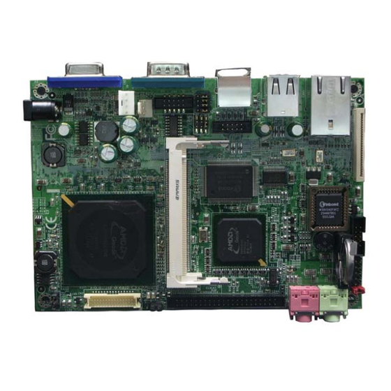
∗ Realtek ALC655 AC97’4-channel Audio Codec integrated Audio ∗ Audio driver and utility included ∗ Award 4MB LPC Flash ROM BIOS ∗ PS/2 keyboard Connector ∗ D-Sub 15-pin VGA Conn.x1 ∗ USB 2.0 connector x 2, USB2.0 header x1 Multi I/O ∗... - Page 10 AMD Geode LX800 Processor 12V CN Reset Power On/Off Keyboard Connector VGA Conn. VGA_CN LAN Connector Compact Flash slot CS 5539 8110SC USB Port Connector Chipset PCI LAN 2-CH Audio Connector USB Port ATA100 (USB1) ALC 665 IDE Connector AUDIO CODEC...
- Page 11 Mini PCI Slot 4MB Flash ROM BIOS 200-pin SODIMM...
- Page 12 Jumper Name Description Page ATX/AT Mode selecte 3-pin Block CMOS RAM Clear Function Setting 3-pin Block CF Card Master/Slave Mode Select 2-pin Block p.10 Connectors Connector Name Description Page Nano-ITX Power Connector 1Phone Jack p.13 12V CN 12V Power Connector 4-pin Block p.13 VGA CN...
-
Page 13: Chapter 2 Hardware Installation
Chapter 2 Hardware installation Hardware installation Steps Before using your computer, you had better complete the following steps: 1. Check motherboard jumper setting 2. Install CPU and Fan 3. Install System Memory (DIMM) 4. Install Expansion cards 5. Connect IDE, Front Panel /Back Panel cable 6. - Page 14 (2) CMOS RAM Clear (3-pin): J2 A battery must be used to retain the motherboard configuration in CMOS RAM short 1-2 pins of JPAT to store the CMOS data. To clear the CMOS, follow the procedure below: Turn off the system and unplug the AC power Remove ATX power cable from ATX power connector Locate JBAT and short pins 2-3 for a few seconds Return JBAT to its normal setting by shorting pins 1-2...
-
Page 15: Glossary
(3) CF Card Master/Slave Mode(2-Pin) : J3 Slave Master CF Card Master/Slave Mode Glossary Chipset (core logic) - two or more integrated circuits which control the interfaces between the system processor, RAM, I/O devises, and adapter cards. Processor socket - the socket used to mount the system processor on the motherboard. Slot (AGP, PCI, ISA, RAM) - the slots used to mount adapter cards and system RAM. -
Page 16: Install Memory
doing the "computing" in "personal computer" Front Side Bus Frequency - The working frequency of the motherboard, which is generated by the clock generator for CPU, DRAM and PCI BUS. CPU L2 Cache - The flash memory inside the CPU, normally Pentium III CPU has 256K or above, while Celeron CPU will have 128 Install Memory The motherboards provide one 200-pin SMALL OUTLINE DUAL INLINE MEMORY... -
Page 17: Expansion Cards
Press down Plug the golden firmly figure into the slot NOTE! When you install DIMM module fully into the DIMM socket the eject tab should be locked into the DIMM module very firmly and fit into its indention on both sides. WARNING! For the DDR SDRAM CLOCK is set at 166MHz, use only DDR333-compliant DDR Modules. -
Page 18: Assigning Irq For Expansion Card
5. Replace the computer system’s cover. 6. Set up the BIOS if necessary. 7. Install the necessary software driver for your expansion card. 2-5-2 Assigning IRQs For Expansion Card Some expansion cards need an IRQ to operate. Generally, an IRQ must exclusively assign to one use. -
Page 19: Interrupt Request Table For This Motherboard
2-5-3 Interrupt Request Table For This Motherboard Interrupt request are shared as shown the table below: INT A INT B INT C INT D INT E INT F INT G INT H √ Slot 1 √ Onboard VGA √ Onboard USB 1 √... - Page 20 (2) 12V Power Connector (4-pin block):12VCN This is a newly defined 4-pins connector support extra 12V voltage to maintain system power consumption in the case that an AD-Scalar daughter board is used. Without this connector might cause system unstable because the power supply can not provide sufficient current for system.
- Page 21 (4) USB Port connector: JUSB1 The connectors are 4-pins connector that connect USB devices to the system board, and standard RJ45 connector for Network supports 10/100/1000 BASE-T transfer rate. (5)LAN Port connector: LAN1 This connector is standard RJ45 over USB connectors for Network devices connection. LAN1supports 10M/100Mb/1G b/s data transfer rate.
-
Page 22: Headers
(8) PS/2 Keyboard Connector: PS2KB The connectors are for PS/2 keyboard device. (9)Compact Flash Slot (50-pin): CF1 This slot as show in the following picture is used for installing compact flash card. 2-6-2 Headers (1) USB Port Headers (9-pin): USB1 These headers are used for connecting the additional USB port plug. - Page 23 (2)IDE Connector (44-pin block): J11 This connector supports the provided IDE hard disk ribbon cable. After connecting the single plug end to motherboard, connect the two plugs at other end to your hard disk(s). You may also configure two hard disks to be both Masters using one ribbon cable on the primary IDE connector and another ribbon cable on the secondary IDE connector.
- Page 24 JW FP Power Reset System Case Connections (5) Serial Port Connector (9-pin female): COM1/COM2/COM3/COM4 COM1~COM4 are 9-pin block pin-headers. The on-board serial port can be disabled through BIOS SETUP. Please refer to Chapter 3 “INTEGRATED PERIPHERALS SETUP” section for more detail information. Pin1 Serial COM Port 9-pin Block...
-
Page 25: Starting Up Your Computer
Starting Up Your Computer 1. After all connections are made, close your computer case cover. 2. Be sure all the switch are off, and check that the power supply input voltage is set to proper position, usually in-put voltage is 220V∼240V or 110V∼120V depending on your country’s voltage used. - Page 26 Beep Meaning One short beep when displaying logo No error during POST Long beeps in an endless loop No DRAM install or detected One long beep followed by three short Video card not found or video card memory beeps High frequency beeps when system is CPU overheated working System running at a lower frequency...
-
Page 27: Chapter 3 Introducing Bios
Chapter 3 Introducing BIOS The BIOS is a program located on a Flash Memory on the motherboard. This program is a bridge between motherboard and operating system. When you start the computer, the BIOS program will gain control. The BIOS first operates an auto-diagnostic test called POST (power on self test) for all the necessary hardware, it detects the entire hardware device and configures the parameters of the hardware synchronization. -
Page 28: Entering Setup
Entering Setup Power on the computer and by pressing <Del> immediately allows you to enter Setup. If the message disappears before your respond and you still wish to enter Setup, restart the system to try again by turning it OFF then ON or pressing the “RESET” button on the system case. - Page 29 CMOS Setup Utility – Copyright(C) 1984-2007 Award Software Standard CMOS Features Load Fail-Safe Defaults Advanced BIOS Features Load optimized Defaults Advanced Chipset Features Set Supervisor Password Integrated Peripherals Set User Password Power Management Setup Save & Exit Setup PnP/PCI Configurations Exit Without Saving ↑↓→←...
-
Page 30: Standard Cmos Features
PnP/PCI configurations This entry appears if your system supports PnP/PCI. PC Health Status This entry shows your PC health status. Load Fail-Safe Defaults This menu uses a minimal performance setting, but the system would run in a stable way. Load Optimized Defaults Use this menu to load the BIOS default values that are settings for optimal performances system operations. - Page 31 Phoenix – AwardBIOS CMOS Setup Utility Standard CMOS Features Date (mm:dd:yy) Mon, Jan, 18 2008 Item Help Time (hh:mm:ss) 11 : 02 : 35 > IDE Primary Master None Menu Level > > IDE primary Slave None Video EGA/VGA Change the day, month, Halt On All Errors year and century...
-
Page 32: Advanced Bios Features
If the controller of HDD interface is CD-ROM, the selection shall be “None” Access Mode The settings are CHS, LBA, Auto and Large. Cylinder number of cylinders Head number of heads Precomp write precomp Landing Zone landing zone Sector number of sectors Advanced BIOS Features Phoenix –... - Page 33 Disabled (default) No warning message to appear when anything attempts to access the boot sector or hard disk partition table. Enabled Activates automatically when the system boots up causing a warning message to appear when anything attempts to access the boot sector of hard disk partition table.
- Page 34 Sets the delay time after the key is held down before is begins to repeat the keystroke. The settings are 250, 500, 750, and 1000. Security Option This category allows you to limit access to the system and Setup, or just to Setup. System The system will not boot and access to Setup will be denied if the correct password is not entered at the prompt.
-
Page 35: Advanced Chipset Features
Advanced Chipset Features The Advanced Chipset Features Setup option is used to change the values of the chipset registers. These registers control most of the system options in the computer. Phoenix – AwardBIOS CMOS Setup Utility Advanced Chipset Features CPU Frequency 500MHz Item Help Memory Frequency... - Page 36 When synchronous DRAM is installed, the number of clock cycles of CAS latency depends on the DRAM timing. The settings are: Auto, 1.5, 2.0, 2.5, 3.0, 3.5. Video Memory Size: The user could choose from : Disabled, 8M, 16M, 32M, 64M, 128M and 256M. The default setting is 8M.
-
Page 37: Integrated Peripherals
Integrated Peripherals CMOS Setup Utility – Copyright(C) 1984-2004 Award Software Integrated Peripherals Master Driver PIO Mode Auto Item Help Slave Driver PIO Mode Auto IDE Primary Master UDMA Auto Menu Level > IDE Primary Slave UDMA Auto IDE DMA Transfer Access Enabled IDE HDD Block Mode Enabled... -
Page 38: Power Management Setup
IDE HDD Block Mode Block mode is also called block transfer, multiple commands, or multiple sector read/write. If your IDE hard drive supports block mode (most new drives do), select Enabled for automatic detection of the optimal number of block read/writes per sector the drive can support. The settings are: Enabled, Disabled. -
Page 39: Irq Wakeup Event
Time(hh:mm:ss) Alarm You can choose what hour, minute and second the system will boot up. Note:If you have change the setting, you must let the system boot up until it goes to the operating system, before this function will work 3-8-1 IRQ Wakeup Events Phoenix –... -
Page 40: Load Fail-Safe Defaults
CMOS Setup Utility – Copyright(C) 1984-2004 Award Software PnP/PCI Configurations PNP OS Installed Item Help Init Display First PCI slot Reset Configuration Data Disabled Resources controlled by Auto ESCD Menu Level > IRQ Resources Press Enter Memory Resources Press Enabled PCI/VGA Palette Snoop Disabled ↑↓... -
Page 41: Load Optimized Defaults
Pressing <Y> loads the default values that are factory settings for stable performance system operations. 3-11 Load Optimized Defaults Load Optimized Defaults When you press <Enter> on this item, you get a confirmation dialog box with a message similar Load Optimized Defaults (Y/N)? N Pressing <Y>... -
Page 42: Chapter 4 Driver & Free Program Installation
configuration. Additionally, when a password is enabled, you can also require the BIOS to request a password every time your system is rebooted. This would prevent unauthorized use of your computer. You determine when the password is required within the BIOS Features Setup Menu and its Security option. - Page 43 From MAGIC INSTALL MENU you may make 7 selections: 1. VGA install AMD Geode LX800 VGA driver 2. SOUND install Realtek ALC655 Codec Audio Driver 3. LAN install Realtek RTL8110SC Ethernet NIC Driver 4. PC-CILLIN install PC-CILLIN 2007 Anti-Virus Program 5.
-
Page 44: Vga Install Amd Geode Lx800 Vga Driver
4-1 VGA Install AMD Geode LX800 VGA Driver 1. Click ‘ this time only’ and then click Next on 2. Choose ‘install from a list or specific the find new hardware wizard window. location(advanced)’and then click Next. 2. Click ’Select for the best driver in these 3. -
Page 45: Sound Install Realtek Alc665 Codec Audio Driver
Two methods to install the VGA Driver: 1. After you install all other drivers and restart the computer, the computer will auto-detect if there are any motherboard driver that have not been installed and you can follow the steps listed above to install the VGA Driver. 2. - Page 46 3. Click Finish and Restart Window. 4. Sound effect. 5. Equalizer. 6. S/PHIF-in settings. 7. S/PDIF- out settings. HRTF demo.
-
Page 47: Lan Install Realtek 8110Scethernet Nic Driver
9. Mic effect settings. 10.General settings. NOTE: Please upgrade your Windows XP to Service Pack 1 / Windows 2000 to Service Pack 4 or later before you the Audio CODEC driver. Install Realtek RTL8110SC Ethernet NIC Driver 1. Click LAN when Magic Install Menu appear 2. -
Page 48: Pc- Cillin Install Pc-Cillin 2006 Anti-Virus Program
3. Click Install to install driver. 4. Click Install to install driver and Click Finish end the installation. PC-CILLIN Install PC-CILLIN 2007 Anti-virus program Click PC-CILLIN when MAGIC INSTALL Select “Install program” when the "PC-Cillin MENU appears internet security 2007" window appears. - Page 49 Click Next to continue. This is license agreement, select "I Accept the terms" and Click NEXT Choose the installation type and the path of 6.Select the two items and then click Next. the file to be installed. then click Next.
-
Page 50: Crypto Install Crypto Encryption/Decryptiondriver
7.The installation status. 8.Setup Complete and click FINISH. Note : Please install ACROBAT READER for reading PC-CILLIN 2007 User Manual which locates at the path “X:\acrobat\adberdr6_enu_full.exe”. 4-5 CRYPTO Install CRYPTO Encryption/Decryption Driver 1. Click ‘ this time only’ and then click Next on 2. - Page 51 3. Click ’Select for the best driver in these 4. Click “FINISH” to complete the installation. location ’ and ‘include this location in the search’, then browse to find the file j8f9/amd_ase. Two methods to install the VGA Driver: 1. After you install all other drivers and restart the computer, the computer will auto-detect if there are any motherboard driver that have not been installed and you can follow the steps listed above to install the CRYPTO Driver.
-
Page 52: How To Update Bios
How to Update BIOS Before update BIOS users have to “Disable”, “Flash Part Write Protect” item which in “Miscellaneous Control” of BIOS SETUP. Otherwise the system the will not allow you to upgrade BIOS by Award Flash Utility. STEP 1. Prepare a boot disc. (you may make one by click START click RUN type SYS A: click OK) STEP 2. - Page 53 software) to satisfy your needs of all sorts of system protections. What functions does Pro Magic Plus have? Instant System Restoration – Regardless of mis-operation or system crash, install Pro Magic Plus beforehand would allow you to instantly restore your system back by simply reboot your computer.
- Page 54 NOTE: Functions of each version will differ from each other, and will be based on the function descriptions of each version. System Requirements ◇ First OS must be Windows 98 SE/ME/2000/XP ◇ Support Only Windows OS (No Linux) ◇ Windows server OS and Windows NT not supported ◇...
-
Page 55: Appendix
Appendix 1. Motherboard Dimensions... - Page 56 **For highly integrated all the features of this motherboard, we can not avoid that some problems of interference occur in some particular situation. Please note that if you need to utilize PCI cards, make sure that the length of them will be limited in 125 mm with the bracket.
- Page 57 3. USB Cable Pin-Definition...
Need help?
Do you have a question about the Geode LX800 and is the answer not in the manual?
Questions and answers