Table of Contents
Advertisement
Advertisement
Table of Contents

Related Manuals for Kverneland Exacta-TL-GEOSPREAD GS3


Summary of Contents for Kverneland Exacta-TL-GEOSPREAD GS3
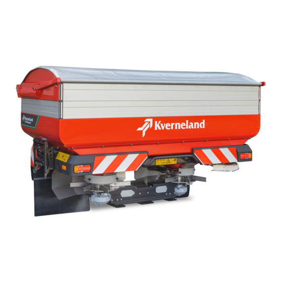
- Page 1 Exacta-TL-GEOSPREAD WARNING: Cancer and Reproductive Harm - www.P65warnings.ca.gov Operator’s Manual Item 06-2021 Print date 06.2021 Language From software version V xxx From machine number 1001 Serial number From VN401 Reference number A148815640...
- Page 2 Hoofdweg 1278 NL-2153 LR Nieuw-Vennep The Netherlands Kverneland Group Nieuw-Vennep B.V holds all copyrights and rights of use. The contents of this user manual can be modified without prior notification. All rights reserved. The right to technical revision is reserved.
-
Page 3: Table Of Contents
Table of contents Table of contents Preface ............Oil and grease content Target group of this manual Maintenance intervals Meaning of symbols Lubricating points Applying or adding grease Safety ............Apply oil For your safety Torques in ft.lb Other guidelines Stainless steel tightening torques ft.lb Safety labels Stainless steel tightening torques (Nm) -
Page 4: Preface
Preface Preface Target group of this This manual is in6tended for agrarians and others trained in working in the field of agriculture, people that are competent to operate these manual machine, as required by national legislation, and who have knowledge of assembly activities and familiarity with assembling equipment. -
Page 5: Meaning Of Symbols
Preface Meaning of symbols California Proposition 65 WARNING Engine exhaust, some of its constituents, certain machine components and fluids, contain or emit chemicals known to the State of California to cause cancer and birth defects or other reproductive harm Various symbols are used to provide a clear understanding of the text. SAFETY FIRST This symbol, the industry's "Safety Alert Symbol", is used throughout this manual and on labels on the machine itself to warn... - Page 6 Preface...
-
Page 7: For Your Safety
Safety Safety For your safety In this chapter you will find general safety instructions. In every next chapter you will find more specific safety instructions not described here. Do not risk injury or death by ignoring good safety instructions. Many risks can happen when working with agricultural machines. Avoid accidents! Do not take risks! Be alert! Think safety! Work in safety! Disregard of the 'Safety instructions', inadequate maintenance, use of... -
Page 8: Safety Labels
Safety Safety labels Various safety labels have been affixed to the machine for safety rea- sons. Do not remove them! Always follow the instructions supplied and be alert to possible dangers. Always keep the safety labels clean and clearly legible. Replace safety decals that are missing, damaged or have become illegible. - Page 9 Safety Safety labels DANGER PARTS EJECTED AT SPEED Parts may become detached and ejected at speed. To avoid death or serious injury: Keep in a safe distance. ROTATING DRIVELINE SHIELD MISSING CONTACT CAN CAUSE DEATH DO NOT OPERATE KEEP AWAY! DO NOT OPERATE WITHOUT- ALL DRIVELINE, TRACTOR AND...
-
Page 10: Safety Requirements
Safety Safety requirements This chapter contains all the requirements, everything that is not permitted and requirements for each form of usage, maintenance and reparation of the machine. The chapters in the manual contain additional safety measures. Knowledge of the safety regulations forms the basis for safety and proper usage of the machine. - Page 11 Safety Authorization Only to be used by an authorized person The machine may be used by authorized people only. A person is authorized if he/she: • received training as required by the national authorities, • has taken responsibility as described in ...
- Page 12 Safety Workplace To be used and operated by 1 person The machine may only be operated by one person, from the tractor. Operating the machine from the tractor will keep you out of harm's way. Other people should not be in the direct vicinity of the machine and the tractor.
- Page 13 Safety Put a fire extinguisher in place Carry a fire extinguisher at all times, especially when operating in dry crop materials. This should be a multipurpose ABC rated extinguisher with a 11 lb. capacity, approved by the appropriate authority. Mount this on the tractor and/or on the machine.
- Page 14 Safety Required details The following details are necessary in order to calculate the minimum requirements and actual axle load, as well as the actual and maximum total weight. The details of the tractor should be given in the tractor manual. The details of the tires should be supplied by the manufacturer.
- Page 15 Safety Calculations The calculations can be made with the values given in the above- mentioned chart. Actual total weight The actual total weight must not exceed the permitted total weight. The actual total weight (in lb) is calculated as follows: Actual total weight (lb) = A + D + E Actual front axle load The actual front axle load must not exceed the permitted maximum...
- Page 16 Safety Ballast required in the rear The minimum load on the rear axle must be 45% of the basic weight of the tractor. With a machine mounted in the front power lift the minimum required ballast (in lb) in the power lift behind the tractor is calculated as follows: ( D x f ) - ( C x g ) + (0.45 x A x g ) Rear ballast required (lb) =...
- Page 17 Safety Machine Check the condition of the machine before use Check the following before using the machine: • is the machine in a proper, functioning condition? • are all lights, safety and warning provisions correctly mounted and in good working condition? •...
- Page 18 Safety Coupling shaft Use the correct coupling shaft Only use coupling shafts complying with the manufacturer’s specification for that specific use! In order to ensure protection of both man and machine exercise extreme caution when working at a coupling shaft other then described in this manual and/or on the instruction at the coupling shaft.
- Page 19 Safety Only use after training The machine may not be operated before the user has been properly instructed by the dealer or an authorized representative of the manufacturer. Ensure that you are familiar with all systems and control machines and their functions prior to working with them! It will be too late for that once you are working! Careless usage could lead to injury and damage to the machine.
- Page 20 Safety Transport Check the decoupling ropes of the quick coupling The decoupling ropes must never be tense and must provide sufficient freedom for movement, even with the power lift in the lowest position as it could otherwise accidentally disconnect the quick coupling. Drive carefully Moving behaviour, maneuverability and braking performance are influenced by a trailed machine.
- Page 21 Safety Maintenance Always keep to the prescribed maintenance intervals Take the machine for inspection and maintenance at the intervals as prescribed in this manual. All of the manufacturer's responsibility and the warranty will become null and void if the prescribed intervals are not adhered to.
- Page 22 Safety Avoid contact with materials You should only come into contact with the materials when cleaning the machine. Always wear protective clothing, such as safety gloves, shoes and goggles. Read and adhere to the additional safety instructions and the instructions of the material producer. Contact with the materials could lead to injury.
-
Page 23: Getting Familiar With The Machine
Getting familiar with the machine Getting familiar with the machine Applications of the This PTO shaft driven machine is suited for spreading granular fertilizer on the field and grazing land. machine It is attached • to the three-point power lift of the tractor (Cat. II), or •... -
Page 24: Adjust Carefully
Getting familiar with the machine Adjust carefully The spreader has two actuators per dosing unit to set the application rate and working width independently of each other. Moreover, it is possible to shut 2 of the 3 dosing openings so that the application rate can also be set precisely with a low flowrate, while the risk of blockages remains limited. - Page 25 Getting familiar with the machine Width distribution with The spreading pattern is determined by the transverse distribu- tion. GEOSPREAD The discharge point is the place where the fertilizer granules come into touch with the vanes of the spreading disc and substantially determines width distribution.
- Page 26 Getting familiar with the machine Display of the sections in the The active sections are displayed in black triangles in the main screen main screen for both sides: • The working width of 78 ft is divided into 2 x 6 sections of 6.5 ft. and controlled by the GEOCONTROL.
- Page 27 Getting familiar with the machine RATE control RATE control is a variable application rate triggered by an external sig- nal. No additional licence key is required. See the GEOCONTROL instruction manual MULTIRATE MULTIRATE can be used on your ISOBUS weighing spreader. An additional licence key is required to enable the software module.
-
Page 28: Spreading Pattern
Getting familiar with the machine Spreading pattern Optimum distribution of the fertilizer with minimum impact on the environment can be achieved through the settings and tools described. Full field spreading pattern The full field spreading pattern overlaps 100% A triangular spreading pattern that completely overlaps can be expected with most fertilizer types with an average working width. - Page 29 Getting familiar with the machine Boundary track spreading It is possible to spread right up to the border from the first sprayer tramline with ExactLine (boundary track spreading). with the ExactLine A ExactLine is available for the right and/or the left. Selecting the pattern for border spreading It is not possible to completely cover the field border at the application rate and not have anything go beyond the border.
-
Page 30: The Iso Control System
Getting familiar with the machine The ISO control The ISO control system uses the ISOBUS communication protocol, which makes it suitable for tractors that are also equipped with an system ISOBUS communication system. For tractors that still do not have an ISOBUS connection, your dealer can supply the universal IsoMatch terminal to which you can connect all ISOBUS machines. - Page 31 Getting familiar with the machine The computer calculates the required fertilizer flowrate with the following formula: Working width (ft) x Driving speed (mph) x Application rate (lbs/acre) flowrate required = (lbs/min) Automatic Calibration test With the data from the spreading chart book and the automatic calibration tests that the spreader carries out every 165 lbs.
- Page 32 Getting familiar with the machine The ISO tractor ISOBUS tractor connection The switching functions and data transfer between the tractor terminal or ISO control box and the machine are operated via the ISOBUS. Specifically tilling the site and reacting to deviating field forms or soil compositions is possible through ISOBUS communication.
- Page 33 Getting familiar with the machine The control box The working method and work performance of the IsoMatch control box are described in this user's manual. IsoMatch universal ISOBUS terminal IsoMatch universal ISOBUS Many functions and programmes on one control box The divided colour screen has a flexible division to: terminal •...
- Page 34 Getting familiar with the machine • Extra functions: • Calculator • Internet browser • Camera screen (Camera is optional) • Status bar for time, GPS signal strength and driving direction • Save and read: • Documents • Tractor data • Field particulars •...
- Page 35 Getting familiar with the machine IsoMatch Grip The IsoMatch Grip accessory is a control unit on which most of the im- plement functions used can be operated centrally with one handle. This is available in addition to the ISOBUS terminal such as the Iso- Match.
-
Page 36: Technical Specifications
Getting familiar with the machine Technical specifications Exacta-TL-GEOSPREAD GS3 1500 1875 2150 2550 2800 3225 3450 3900 General Content of the hopper (gal) 1030 Filling level (in) Filling width (in) Hopper's width (in) Weight (lbs) 1466 1499 1532 1565 1598... -
Page 37: Technical Specifications
Getting familiar with the machine Technical specifications Exacta-TL-GEOSPREAD GS3 Sound level Closed cabin Rear window opened Tractor at 540 rpm (dB) 71.9 76.2 Tractor + operating, empty spreader (dB) 71.9 82.3 Tractor + spreading spreader (Kali 60) (dB) 73.8 84.6 Tractor + spreading spreader (Kali 60) + 73.0... -
Page 38: Before First Use
Before first use Before first use Inspection of the The machine would generally be assembled and delivered ready-for- use by the dealer. The dealer is also responsible for providing supplied machine instructions for use and maintenance. He/she must also ensure that the required documents are provided, such as: •... - Page 39 Before first use WARNING Be careful that nothing gets jammed It is easy for parts to get jammed while mounting the spreader. Work carefully: • place the tractor and machine on a firm, flat surface, • switch off the PTO shaft, •...
- Page 40 Before first use Console assembly Mount the control box in a place where it would: • be well visible, Console for the control box • easy to operate while spreading, • and result in minimal visual hindrance while driving the tractor. The console has two range and height adjustments to provide optimal view of the control box.
- Page 41 Before first use IsoMatch terminal on an ISO If you use the IsoMatch control box with a tractor manufactured with the ISOBUS communication system, you can connect it with the tractor supplied 7-pin CAN cable to a standard tractor CAN connection. ...
- Page 42 Before first use Hopper extension A hopper extension increases the load capacity of the spreading hopper. All edges consist of: A long side • 2 long sides, • 2 short sides, • 4 corner parts, • 4 caps, • fixing material. ...
- Page 43 Before first use Parking wheels WARNING Only park with an empty hopper Only park the machine on the parking wheels if the hopper is empty! Parking with a filled hopper results in reduced stability. Moreover, the wheels are not designed for heavy loads. Damages to the machine and physical injury can be caused.
- Page 44 Before first use Set of vanes 330-330-330 A set of vanes is available for larger working widths. The set consists of two different vanes 4x with an angle of 5º and 8x with an angle of 10º Grease the threaded rods of the vanes. fixed vane ...
- Page 45 Before first use Hydraulic drive A hydraulic drive is available to power the machine without PTO shaft. The tractor must have a minimum oil yield of 13 gal/min (2320 psi). The maximum yield is 550 lbs/min in combination with the 330- 330-330 set of vanes.
- Page 46 Before first use Linkage frame Linkage frame for tractors with power lift of Cat. 3 / 4 for connecting the spreader to the tractor. Also see the spare parts manual for the correct assembly. Reflector Motor vehicles with limited speed (<25 mph), agricultural and forestry tractors and their trailers, as well as other vehicles, must be provided with an orange triangle with a red reflector at the rear in the form of a truncated triangle.
- Page 47 Before first use Coupling shaft connection The working width of the machine is mostly determined by the RPM of the spreading disc. The speed of the spreading disc depends on the point speed of the PTO shaft and the chosen connection from the coupling shaft.
- Page 48 Before first use Hydraulic border spreading plate Fit the frame to the machine; see also the spare parts manual. Fit the laminated box to the frame. Sensor Frame Connect the position sensor in the electronic box on the spreader: ...
- Page 49 Before first use Calibration container The calibration container is used to control the dosing setting of the machine. The calibration container must be mounted on the left spreading disc driving rod for the calibration test. Remove the vanes. Turn the nuts on the bolts on which the gearbox is mounted to the turning rod back 5 mm/0.2 in.
-
Page 50: Tractor Provisions
Before first use Tractor provisions Working with the machine requires a tractor that at least meets the following requirements. • Sufficient carrying and lifting capacity and engine power. see paragraph »Technical specifications« on page 36, • Correct type of properly adjustable power lift, •... -
Page 51: Mounting The Coupling Shaft
Before first use Mounting the coupling shaft WARNING The coupling shaft provided is too long for most types of tractors The coupling shaft must be cut to the correct length before connecting it to the tractor. A coupling shaft that is too long could lead to serious damage to the machine and the tractor. - Page 52 Before first use Shortening the coupling The profiled tubes must overlap as far as possible, with a minimum of 5.91 shaft The profiled tubes must however have at least 25 mm/1 in. free clearance at the outer edges when the tractor PTO shaft and the machine drive axle are level.
-
Page 53: Connecting To The Tractor
Connecting to the tractor Connecting to the tractor WARNING Neutralize the controls Control devices, e.g. ropes, hoses, etc. for remote actuation of devices such as cylinders, shall be guided and positioned in a way they never inadvertently release nor block desired movements/ actuations! Unintentional movements can lead to serious injury. -
Page 54: Selecting Linkage Pin Height
Connecting to the tractor WARNING Check the coupling shaft Check the following points before the PTO shaft is attached. Has the coupling shaft: • no damage, including the protection sleeves? • are there sufficient lubricants as prescribed? • is the prescribed overlap of the coupling shaft halves and pro- tection sleeves, both in transport and in operating position? •... -
Page 55: Connecting The Machine
Connecting to the tractor Connecting the The space between the spreader and the tractor is limited as far as possible in order to keep the centre of gravity as closely to the tractor machine as possible. This promotes stability and the road behaviour of the tractor. - Page 56 Connecting to the tractor Coupling the coupling shaft WARNING The coupling shaft provided is too long for most types of tractors The coupling shaft must be cut to the correct length before connecting it to the tractor. A coupling shaft that is too long could lead to serious damage to the machine and the tractor.
- Page 57 Connecting to the tractor Connecting hydraulic hoses WARNING Valves If the machine is equipped with ExactLine (accessory) the hydraulic hose must be connected for operation. Check the hydraulic quick coupling on the tractor for dirt. Clean if necessary. Remove the hose from the hose coupling support and check the quick coupling for dirt.
- Page 58 Connecting to the tractor Connecting the power lift WARNING Check the decoupling ropes of the quick coupling The decoupling ropes must never be tense and must provide sufficient freedom for movement, even with the power lift in the lowest position as it could otherwise accidentally Disengage the quick coupling.
-
Page 59: To Be Done Before Spreading
To be done before spreading Find the correct settings To be done before spreading of the spreader and set it WARNING accordingly Avoid contact with the fertilizer and other material You will most likely get into contact with the fertilizer and other material you may wish to spread while filling, adjusting and testing the spreader. - Page 60 To be done before spreading Determine the type of fertiliser based on the shape and surface: Type Operation pattern Surface Granular rough roughly round, sometimes slightly rough angular, no sharp corners or edges smooth roughly round, not angular, no relatively smooth sharp corners or edges mineral angular, with sharp angles and...
- Page 61 To be done before spreading Determining distribution The distribution is the ratio of granules with different diameters. A distribution meter comes with every spreader. This meter has 4 sections, with sieves. The sieves have different mesh width that divide the fertilizer granules, based on their diameters. ...
- Page 62 To be done before spreading Determining similar weight The density is the specific weight (lbs) of 1 square feet of fertilizer and it is expressed as lbs/qu.ft . The following material is required to determine the density: • measuring beaker (supplied), •...
- Page 63 Exacta-TL(X). Except for the discharge opening, the spreader then has to be set manually. Telephone App Using the Kverneland group spreading charts application, you can easily find the right settings for your spreader. The spreading charts application gives you immediate access to the most up-to-date test results of fertiliser.
-
Page 64: Setting The Spreader
To be done before spreading Setting the spreader WARNING Avoid contact with the fertilizer and other material You will most likely get into contact with the fertilizer and other material you may wish to spread while filling, adjusting and testing the spreader. - Page 65 To be done before spreading The spreading chart from the example looks as follows: 59 ft 66,2 lb/ft³ NPK 17-17-17 Grande Paroisse (AZF) lb/ac lb/min lb/min - 30 - Granulaat 18+0 18+3 75 cm < 55 cm 24+0 24+3 570 rpm 0°...
-
Page 66: Working Width
To be done before spreading Working width The working width must be selected to set the spreader. This could for instance be the distance between the sprayer tramlines. Turn to the page in the spreading chart book that contains details about the selected working width for the fertilizer type with the most comparable features. -
Page 67: Inclination
To be done before spreading Discharge point It is necessary to correctly set the discharge point in order to obtain a good spreading pattern and the correct working width. The point at which the granules or seeds come onto the spreading disc can be changed by setting the discharge point. -
Page 68: Application Rate
To be done before spreading Application rate The control system can drive the spreader in three different ways: • distribution that resembles the settings for the preset application rate must be determined under changing circumstances through automatic calibration and driving speed correction, ... - Page 69 To be done before spreading Fine application All three dosing openings normally open uniformly with the selected application rate and the corresponding flowrate that you set. With a Dosing openings low application rate and/or a low driving speed the dosing openings are only opened a slight bit so that very little fertilizer would stream through the dosing openings of the spreader.
- Page 70 To be done before spreading Dosing setting The dosing setting to be set can be: • Read from the relevant spreading chart if a lower application rate is to be used whereby the fine application kit is used and Fine application kit is indicated under the heading in the spreading chart: yes.
- Page 71 To be done before spreading Suppose you would want to spread slug pellets with the characteris- tics given in the spreading chart below: With a working width of 59 ft., a driving speed of 5 mph and a selected application rate of 9 lbs/acre.
- Page 72 To be done before spreading Suppose you would want to spread NPK 17-17-17 from the example with the features as given in the spreading chart on this page: With a working width of 59 ft, a driving speed of 5 mph and a selected application rate of 21 lbs/acre.
- Page 73 To be done before spreading Manual calibration test WARNING PTO shaft rotates after disengaging After switching off the PTO shaft, danger could arise as the machine will continue running because of inertia. Keep a safe distance to the machine until the moving parts have come to a complete stop.
- Page 74 To be done before spreading Variable, externally driven The control system provides the options to distribute the same application rate all over the field and the option to spread a variable, application rate externally driven application rate. This provides the option to spread as per requirements, e.g.
-
Page 75: Filling
To be done before spreading Filling WARNING Avoid contact with the fertilizer and other material You could come into contact with materials when filling the machine. Always wear protective clothing, such as safety gloves, shoes and goggles. Read and adhere to the additional safety instructions and the instructions of the material producer. - Page 76 To be done before spreading Most types of fertilizer attract water and can thereby form large NDICATION chunks. These chunks can block the spreader or distort the spreading pattern. • When working under moist conditions, use a hopper cover that closes well.
- Page 77 To be done before spreading Work carefully while filling and take the regulations that apply to NDICATION working conditions into consideration! Make sure no objects or tools fall into the hopper as it could block or damage the spreader! Close the hopper cover. WARNING Do not exceed the maximum total weight of 10825 lbs! ...
-
Page 78: Spreading Pattern Check (Tray Test)
To be done before spreading Spreading pattern check (tray test) WARNING Avoid contact with the fertilizer and other material You will most likely get into contact with the fertilizer and other material you may wish to spread while filling, adjusting and testing the spreader. - Page 79 To be done before spreading When to perform the tray test: • When using fertilizer types not indicated in the spreading chart book. • When using fertilizer types with varying distribution and density from the values indicated in the spreading chart book. •...
- Page 80 To be done before spreading Test the left and right The left and right spreading discs must spread the same volumes of fertilizer to ensure good distribution. Check this every year! spreading patterns This test describes a working width of 59 ft. You are of course free to NDICATION run the test for a different working width.
- Page 81 To be done before spreading Start the tractor again. Close all the doors and windows in the cabin. Switch the control box on. Press the desired application rate in the input field. Press the OK key to confirm the set application rate. ...
- Page 82 To be done before spreading Assessment Record the values you find in the graduated tubes for the left and right spreading discs. Compare the values, calculate the percentage differences between the measuring tubes on the left and the right. Adaptation If the spreading patterns on the left and right spreading discs are not the same and the difference is greater than 3% you will have to do the...
- Page 83 To be done before spreading Full field spreading pattern If the spreader is correctly set and the tramlines are set at the correct distance from each other you would achieve a good distribution of test fertilizer over the land. This will only be achieved if the spreader spreads with the correct spreading pattern.
- Page 84 To be done before spreading Start the tractor again. Close all the doors and windows in the cabin. Switch the control box on. Press on the input field for the required application rate. Key in the new value on the popup keyboard. The new value is on the screen of the keyboard.
- Page 85 To be done before spreading Review and adaptation The content of the separate tubes can differ 15% at most from the average. If the correction seems to be 2 characters too strong after repeating NDICATION the test, set the discharge point back by one character. Good spreading pattern, the spreader has been adjusted well.
- Page 86 To be done before spreading Testing the spreading When using the border spreading plate the aim is to obtain maximum distribution to the border with minimum loss in the ditch. pattern of the border This is then why the border spreading plate has to be tested. Do not spreading plate perform this test next to the ditch, rather mark a line behind which the fictive ditch will be.
- Page 87 To be done before spreading Start the tractor again. Close all the doors and windows in the cabin. Switch the control box on. Press on the input field for the required application rate. Key in the new value on the popup keyboard. The new value is on the screen of the keyboard.
- Page 88 To be done before spreading Position of the border Mount the border spreading plate on another position when using the border spreading plate and the set of vanes 330-330-330 (option). spreading plate For this purpose, a plate is supplied with the set of vanes 330-330- 330.
- Page 89 To be done before spreading Testing the spreading Always perform a calibration test first and determine the correct dosing setting before checking the spreading pattern. Changes to the pattern of the border dosing setting will also have an influence on the spreading pattern! spreading plate ...
- Page 90 To be done before spreading Place 1 trough on the land next to the fictive border ditch and 2 troughs next to each other in the fictive ditch. Start the tractor and engage the PTO shaft. The correct PTO shaft rpm is the standard value, less 25%, being 540 rpm - 25% = 400 rpm.
- Page 91 To be done before spreading Should you want to use the H2O setting for border spreading, longer plates are supplied separately with the hydraulic border spreading plate. In this case, follow the settings of the H2O spreading chart. The positions in the H2O position are A to D and are indicated in the spreading charts.
- Page 92 To be done before spreading Ditch side Review and adaptation The maximum acceptable loss in the ditch is determined by environment standards (EN 13739-1). In order to comply with the standards the quantity of fertilizer in the 1st trough, standing in the imaginative ditch, must be a maximum of 10% of the quantity collected in the trough in the middle of the track (= 100%).
- Page 93 To be done before spreading Testing the full field Reducing the PTO shaft rpm and closing the right spreading disc also have an influence on the spreading pattern on the left side of the spreading pattern with the spreader. The full field spreading pattern should therefore be tested border spreading plate when using the border spreading plate.
- Page 94 To be done before spreading Testing the spreading When using the ExactLine the aim is to obtain maximum distribution to the border with minimum loss in the ditch. pattern of ExactLine This is why the ExactLine has to be tested. Do not perform this test next to the ditch, rather mark a line behind which the fictive ditch will Operation ...
- Page 95 To be done before spreading Place 1 trough on the land next to the fictive border ditch and 1 trough next to each other in the fictive ditch. : Position the troughs horizontally with a spirit level! NDICATION Place 1 trough in the middle of the tractor tracks. The driving track must be half a working width from the fictive ditch.
- Page 96 To be done before spreading Review and adaptation Ditch side The maximum acceptable loss in the ditch is determined by environment standards (EN 13739-1). In order to comply with the standards the quantity of fertilizer in the 1st trough, standing in the imaginative ditch, must be a maximum of 10% of the quantity collected in the trough in the middle of the track (= 100%).
-
Page 97: Driving On The Road
Driving on the road Before taking to the Driving on the road road WARNING Observe the permissible and safe height with regard to • prescribed maximum height for vehicles in the road traffic reg- ulations, • high-voltage cables or other cables over the road; •... -
Page 98: Preparing The Machine To Be Transported
Driving on the road Preparing the machine to be transported WARNING Before travelling on a public road with your tractor and machine, you should do the following: Check whether tractor and machine are roadworthy. Check that the lights, warning indicators, protectors and brakes are attached properly and are working. -
Page 99: Use In The Field
Use in the field Use in the field WARNING Friction between moving parts: Be careful of moving parts making contact with each other while working. You could accidentally touch control levers and cause the machine to move. Only start working once all machine parts have stopped and the control lever have been secured. -
Page 100: Adjusting The Machine
Use in the field Most types of fertilizer attract water and can thereby form large NDICATION chunks. These chunks can block the spreader or distort the spreading pattern. • When working under moist weather conditions, use a hopper cover that closes well. •... - Page 101 Use in the field Last setting check A checklist is given below, as well as in the jacket of the spreading chart. Do this last check to ensure good spreading results. Are you working with the correct settings from the correct spreading chart, based on: •...
-
Page 102: Spreading On Field
Use in the field Spreading on field Working with the GEOCONTROL Starting a new task is done from a saved field or one to be created newly with the GEOCONTROL application. Refer to the GEOCONTROL manual in your terminal for this purpose. - Page 103 Use in the field Tramline patterns Your preferred border spreading method determines the tramline pattern. Select on the basis of the site width, the presence of the spreader tramlines and the spreader's equipment. Using ExactLine with tramlines Drive half the working width from the field edge (1/2 X ft.) when doing boundary track spreading with ExactLine (optional extra).
- Page 104 Use in the field Using the border spreading plate During one-sided boundary spreading with border spreading plate, with tramlines you drive along the outermost work area on the field edge and control the fertilizer granule stream by means of the border spreading plate (accessory).
-
Page 105: Start Spreading
Use in the field Start spreading To begin spreading, proceed as follows: Close all the doors and windows in the cabin. Drive the tractor to the first tramline, depending on the driving pat- tern required, which may be recognised by the marker in place. ... - Page 106 Use in the field approaching headland with the GEOCONTROL function switched off: Close the dosing units by pressing the stop key before turning to the headland. The PTO shaft can keep running if you intend to start spreading immediately again. You will find the correct procedure and corresponding distances on the headland in ...
- Page 107 Use in the field Working method on the The driving pattern that you use, in other words how you must turn on the headland, depends on your border spreading method. headland • spreading the border from the sprayer tramline with ExactLine, one-sided border spreading with additional room with the border spreading plate (situation A), or •...
- Page 108 Use in the field Border spreading plate Set the field boundary as close as possible to the left while driving along the field boundary, to spread right down to the border with the border spreading plate. Fill the headland through to half the working width without the border spreading plate with the correct dosage selected to make an additional pass.
- Page 109 Use in the field GEOCONTROL headland function Begin with creating the field boundary where you spread down to the border along the field boundary while driving to the left with the border spreading plate and the correct dosage switched off. ...
- Page 110 Use in the field Over and underdosing Depending on soil or crop composition, it is preferable to spread more or less fertiliser locally. With the control system, you can over- or under dose to the left, right or on both sides during spreading. You will find all the control keys on the main screen.
-
Page 111: Border Spreading
Use in the field Border spreading Spreading fertiliser up to the border of the property requires concen- tration. On the one hand you want to achieve maximum cover to the field edge to ensure a good crop, while on the other hand you want to minimise the loss over the field edge. - Page 112 Use in the field The maximum acceptable loss over the field edge is determined by environment standards (EN 13739-2). In order to comply with the standard the quantity of fertiliser spread beyond the field edge must be a maximum of 10% of the quantity distributed in the centre behind the spreader (= 100%).
- Page 113 Use in the field Procedure with hydraulic The procedure is almost the same as with the border spreading plate. Left and right border spreading is possible with the hydraulic border border spreading plate spreading plate. See »Setting the hydraulic border spreading plate« on page 90, Border spreading with the Mount the border spreading plate into another position with this set of vanes.
- Page 114 Use in the field Driving pattern Two different driving patterns can be used, depending on the situation on your land. Only drive counter-clockwise (to the left) when using the border NDICATION spreading plate and ExactLine. Working from the sprayer tramlines (situation A): ...
- Page 115 Use in the field Boundary track spreading with the ExactLine Operation Drive half the working width from the field edge (1/2 X ft.) (=first sprayer tramline) when doing boundary track spreading with ExactLine (optional extra). The flow of fertilizer granules, seeds or other granules spread with ExactLine.
- Page 116 Use in the field you can choose from 3 settings from the chart: • YIELD. • ECO, • In the yield setting (YIELD), the loss over the field edge is higher than what is allowed by the environmental standard. Therefore, never use this setting next to surface water.
- Page 117 Use in the field Procedure Engage the ExactLine by letting the relevant single-acting Accumulator hydraulic valve run for a few seconds. This is also how pressure is built in the accumulator. You will see the ExactLine symbol on the main screen.
-
Page 118: Stopping Work
Use in the field Driving pattern When using the ExactLine, drive in the first sprayer tramline or half the working width (1/2 X ft.) from the field edge. 1/2 X m (ft) Stopping work WARNING Right after working with the machine, before you leave, you must do the following: ... -
Page 119: Failure And Stoppage
Use in the field Failure and stoppage WARNING Be careful that nothing gets jammed It is also easy to get injured while working with the spreader. Work safely with the machine: • place the tractor and machine on a firm, flat surface, •... - Page 120 Use in the field These failures are probably caused by one of the following: • a hard object blocks the agitator, • a hard object or a large piece of fertilizer is (partially) blocking the supply from flowing to the agitator, •...
- Page 121 Use in the field Examine the spreading discs and the discharge opening to see what the cause of the failure/stoppage is. Adapt the discharge point as needed for easier access. If you still cannot see the cause, carefully remove the vanes to see better into the discharge opening of the discharge bushing.
- Page 122 Use in the field stoppage If you have not found any damage, the failure is probably due to stoppage from an encrusted layer of fertilizer. Try to reduce the size of the lump or encrusted layer with an object such as a stick, screwdriver or vane.
-
Page 123: Rangement De La Machine
Rangement de la machine Rangement de la machine WARNING Avoid contact with the fertilizer and other material It is easy to come into contact with the materials when putting away the machine. Always wear protective clothing, such as safety gloves, shoes and goggles. Read and adhere to the additional safety instructions and the of the material producer. -
Page 124: Storing The Machine
Storing the machine Storing the machine Cleaning If the machine is being put away for a short or longer period of time it is recommended that you lubricate and clean it first. If it is lubricated first you will prevent dirt, fertilizer and water from entering the bearings. -
Page 125: Disconnecting The Machine
Storing the machine Disconnecting the machine WARNING Disconnect safely You may only disconnect the machine when • all parts are in a safe condition, • your immediate surroundings are safe, • the hopper is empty. Work carefully: • check the environment (children!) and ensure that nobody is in the vicinity of the tractor or the machine. - Page 126 Storing the machine If you cannot lower the power lift far enough to release the catch hooks, we advise you to place the spreader on a firm, stable ramp, for example a pawl. Drive the tractor about 8 in. forward (maximum distance depends on the range of the coupling shaft;...
- Page 127 Storing the machine Preparation for winter At the end of the season the machine must be prepared for winter storage. storage If the machine is being put away for a short or longer period of time it is recommended that you lubricate and clean it first. If it is lubricated first you will prevent dirt, fertilizer and water from entering the bearings.
-
Page 128: Maintenance
Maintenance Maintenance WARNING Repair damage safely and without delay Repair the machine safely before you continue with work: • place the tractor and machine on a firm, straight surface, • switch off the PTO shaft, • switch off the electronic control system, •... - Page 129 Maintenance WARNING Do not modify the machine Do not modify the machine in any way. Unauthorized modifications may impair the function and/or safety and affect the life of the machine. Only use original parts when replacing Using other non-genuine parts could lead to problems and unsafe situations when using the machine.
-
Page 130: Oil And Grease Content
Maintenance Oil and grease content WARNING Never use more oil or grease than prescribed A too high oil level may result in an overheated machine and damaged seals. Waste storage and disposal Waste from performing maintenance on the machine could be contaminated with fertilizer, oil and grease. -
Page 131: Maintenance Intervals
Maintenance Maintenance intervals Keep to the checking and maintenance intervals given below to keep the machine in good working order. Inspection • • »Checking bolts and nuts« • • »Checking the hydraulic system« • Condition of the agitator and the agitator axle •... -
Page 132: Lubricating Points
Maintenance Lubricating points All lubricating nipples of the machine can be filled with a universal grease type. See »Oil and grease content« on page 130. See »Maintenance intervals« on page 131. Coupling shaft with quick Lubricate the 4 nipples. lock ... -
Page 133: Applying Or Adding Grease
Maintenance Applying or adding grease Coupling shaft profiled tubes You must grease the profiled tubes of the coupling shaft regularly. Apply grease to the contact surfaces of both of the profiled tubes should you note during coupling or decoupling that the halves of the coupling shaft are not sliding in and out smoothly. -
Page 134: Apply Oil
Maintenance Apply oil The following parts only function well if they are provided with sufficient oil. Check this regularly. Connectors The connectors between the central gearbox and the spreading disc gearboxes are used with border spreading, with a calibration test and when checking the spreading pattern with the tray test. -
Page 135: Torques In Ft.lb
Maintenance Torques in ft.lb Guidelines for torques (in ft.lb) for self-locking nuts, hexagon bolts and nuts. Torques Quality 10.9 12.9 Friction* 0.10 0.13 0.10 0.13 0.10 0.13 0.10 0.13 Thread 11.1 11.1 13.3 15.5 18.5 22.9 26.6 26.6 11.8 14.0 29.5 36.9 44.3... - Page 136 Maintenance Torques(Nm) Guidelines for torques (in Nm) for self-locking nuts, hexagon bolts and nuts. Torques Quality 10.9 12.9 Friction* 0,10 0,13 0,10 0,13 0,10 0,13 0,10 0,13 Thread 1020 1000 1180 * The friction coefficient of 0.10 applies to oiled sheets, cast iron, hardened surfaces, greased threads, etc.
-
Page 137: Stainless Steel Tightening Torques Ft.lb
Maintenance Stainless steel Guidelines for torques (in Nm) for self-locking nuts, hexagon bolts and nuts. tightening torques ft.lb Torques Quality 70 (A2) 80 (A4) Friction* 0.10 0.20 0.30 0.10 0.20 0.30 Thread 11.8 11.0 17.5 21.7 14.7 23.3 28.5 21.7 34.6 43.0 28.3... -
Page 138: Stainless Steel Tightening Torques (Nm)
Maintenance Stainless steel Guidelines for torques (in Nm) for self-locking nuts, hexagon bolts and nuts. tightening torques (Nm) Torques Quality 70 (A2) 80 (A4) Friction* 0.10 0.20 0.30 0.10 0.20 0.30 Thread 12.2 13.2 16.3 15.2 24.1 29.9 20.3 32.1 39.9 29.9 47.7... -
Page 139: Checking The Hydraulic System
Maintenance Checking the hydraulic system WARNING Hydraulic oil is under high pressure Never try to stop a leak with your fingers. Never try to locate a hydraulic leak or try to contain it by hand! When inspecting always use appropriate aid (e.g. a piece of wood or sheet metal) and wear safety goggles, safety gloves and gloves! High pressure fluid easily penetrates skin and clothes, causing severe injuries. - Page 140 Maintenance Replacement intervals WARNING Regularly inspect the hydraulic system (hoses, pipes, connections). All hoses, piping and connecting points must be checked regularly, but at least once a year, by an expert for leakages or visible damage! The lifetime of a hose can be 6 years maximum (see the production date on the hoses).
-
Page 141: Checking And Setting The Dosing Mechanism
Maintenance Checking and setting the dosing mechanism WARNING Avoid contact with the fertilizer and other material You will most likely get into contact with the fertilizer and other material you may wish to spread while filling, adjusting and testing the spreader. Wear protective clothing and safety gloves, read the safety instructions provided by the supplier and follow their directions. - Page 142 Maintenance Setting the position of the The dosing mechanism must be mounted exactly in the middle above the spreading discs. The agitator axle must turn freely from the seal dosing mechanism ring. agitator If you open the filters, you should block them to prevent unwanted NDICATION closing.
- Page 143 Maintenance Setting the dosing baffles It is necessary to set the dosing plates to the correct positions to each other to ensure correct dosing. If the dosing openings do not close well Cracks you will loose unnecessary fertilizer and the application rate will be higher than intended with a specific dosing setting.
-
Page 144: Checking And Setting The Discharge Point Setting Mechanism
Maintenance Checking and setting the discharge point WARNING setting mechanism Avoid contact with the fertilizer and other material You will most likely get into contact with the fertilizer and other material you may wish to spread while filling, adjusting and testing the spreader. - Page 145 Maintenance Attach the rope as per the illustration. Measure the distance between the inside of the rope and the opening of the discharge bushing carefully. If the measured distance is more or less than 109 mm/4.91 in, do the following: ...
-
Page 146: Checking And Setting The Discharge Bush Height
Maintenance Checking and setting the discharge bush WARNING height Avoid contact with the fertilizer and other material You will most likely get into contact with the fertilizer and other material you may wish to spread while filling, adjusting and testing the spreader. -
Page 147: Agitator Seal
Maintenance If the measured distance is more or less than 1.0 mm/0.04 in, do the following: Remove the dashboard by loosening the 3 fixing knobs. Lock nut Turn the lock nuts on the 4 fastening bolts with which the dosing mechanism is attached to the hopper a few times to loosen them. -
Page 148: Replacing Agitator Axle Seal
Maintenance Replacing agitator axle seal WARNING Avoid contact with the fertilizer and other material You will most likely get into contact with the fertilizer and other material you may wish to spread while filling, adjusting and testing the spreader. Wear protective clothing and safety gloves, read the safety instructions provided by the supplier and follow their directions. - Page 149 Maintenance Open the sieves and lock them. agitator Remove the agitator from the agitator axle. Support the fertilizer bearing ring through a dosing opening so that it will not drop. Remove the 3 fastening bolts from the seal rings. ...
-
Page 150: Accessories
Accessories Accessories General The following accessories for your machine are available to adapt it to your tractor and/or are working conditions. All of the responsibilities of the manufacturer lapse and the warranty becomes null and void if non-genuine parts are used. IsoMatch control box For complete ISO control, the IsoMatch control box offers many extra new functions. - Page 151 Accessories IsoMatch Tellus GO Compact and complete IsoMatch Go, as a handy and more compact variant of the double- control box screen version, offers complete ISO control with all functions. Besides the smaller dimension with the single screen, the number of USB connections and the absence of Wlan/Wifi constitutes the biggest difference.
- Page 152 Accessories Cable with 7-point plugs for ISO Directly to the ISO 11786 in cab tractor connection in the tractor 11786 in cab connection cabin You can mount an optional extension cable to the ISO 11786 in cab tractor connection on the 7-point plug "Input IM Tellus" cable supplied as a standard item.
- Page 153 Accessories Spreader control software A user licence can be purchased via the IsoMatch shop which, after the expiry of the free test period, allows your machine to work with • Task controller • external application rate • control for headland management and GEOSPREAD functions. ...
- Page 154 Accessories ISOMatch InLine To complement the GEOCONTROL functions an optically guided steering instrument will assist you in finding and keeping the A-B line during various activities. DGPS driven steering The upper and middle section shows the DGPS driven steering while spraying and for other treatments, where close monitoring of the pass is required.
- Page 155 Accessories Slow moving vehicle sign A slow moving vehicle (SMV) sign is a reflective orange triangle with a red border that warns other road users that the vehicle displaying the sign is travelling at 40 km/h (25 mph) or less. Hardened vanes In case of intensive spreading of fertilizer with high roughness, interchanging vane positions on the disc is sometimes not enough.
- Page 156 Accessories ExactLine The ExactLine is an accurate boundary track spreading tool for spreading border up from the last sprayer tramline. ExactLine provides a very good border spreading pattern with an optimal balance between profit and the environment. See paragraph »Boundary track spreading with the ExactLine« on page 115.
- Page 157 Accessories Calibration container A calibration test is essential to obtain accurate settings for a manually entered application rate. The calibration container is an indispensable tool for this. Drain kit A drain kit is available for emptying the hopper quickly. Hydraulic drive A hydraulic drive is available to power the machine without PTO shaft.
- Page 158 Accessories Hopper extension The loading volume of the spreader can be increased by putting one, rim in place. Hopper extensions See paragraph »Technical specifications« on page 36. Keep the increase in the filling height and the weight of the machine into account.
- Page 159 Accessories Trailer There is a trailer available with various wheel sizes for spreaders that can hold large volumes behind a small tractor. Keep an increase in loading height of approximately 65 cm/26 in. in mind. See paragraph »Technical specifications« on page 36. Parking wheels set A disconnected machine can easily be moved with the parking wheels set.
-
Page 160: Troubleshooting
Troubleshooting Troubleshooting Troubleshooting table Problem Possible cause Solution Incorrect appli- Dosing setting incorrectly set Check the dosing setting cation rates Incorrect setting for fine dosage Set the dosing setting for fine application (kg per hec- as per the instructions tare) Driving speed signal not correctly set Set the correct source of the driving speed signal in the control system, as well as the... - Page 161 Troubleshooting Problem Possible cause Solution Great amounts Average quality fertiliser (too soft, broken, Contact your supplier. of dust while mixed types) or incorrect storage Update the storage area. spreading Spread with smaller working widths as far as possible Rpm on the spreading discs too high Check the PTO shaft speed and the cou- pling shaft mounting point agitator grinds.
- Page 162 Troubleshooting Problem Possible cause Solution Machine Discharge bushing makes contact with Please contact your dealer makes a noise the spreading disc while running Spreader put down with filled hopper Repair the machine. 141, Set dosing mechanism and discharge point again Spreading disc hidden/ out of balance Check the spreading discs for damage and for the presence of all the vanes...
-
Page 163: Falling Into Disuse
Falling into disuse Falling into disuse When the lifespan of the machine has finished, its separate parts must be properly disposed of. Keep local legislation in mind with this! Metal parts You should dispose at requirements all metal parts appropriately. Plastic parts All plastic parts can be disposed of as unwanted garbage. -
Page 164: Liability
Liability Liability Liability Without prejudice to the other terms of these General Conditions, the seller is only responsible for damage caused by breach of the express warranty: the buyer is completely responsible for damage that result from gross neglect due to the buyers own actions or due to gross negligence of the buyers legal representatives or supervising employees. -
Page 165: Complaints
Liability Complaints The following conditions apply, along with the express limited warranty: • The buyer must check the equipment, accessories and spare parts upon delivery for transport damage and completeness. Any possible shortcomings must be reported without delay. • The seller will only consider complaints if the buyer reports such in writing within fourteen days after delivery by the seller. - Page 166 Notes Notes...
- Page 167 Index Index 330-330-330 Border spreading plate Accessories one-sided boundary spreading border spreading plate operation Calibration container spreading pattern drain kit border spreading plate driving speed signal headland Electric hopper cover Test the spreading pattern hopper cover tramlines hopper extensions Boundary track spreading IsoMatch Grip ExactLine pellet sieve...
- Page 168 Index connecting fitting failure lubricating points causes Maintenance failures safety trouble shooting shorten Falling into disuse coupling shaft connection point fertiliser characteristics density distribution data explosion danger technical mixing diagonal inclination safety adjusting type and shape discharge bush height field inspection Adjusting the machine discharge bushing...
- Page 169 Index hydraulic filling connecting inspection Hydraulic border spreading plate Preparing for transport spreading pattern product life working method safety hydraulic drive safety decals hydraulic hoses Maintenance Inspection criteria actuator replace bolts and nuts Replacement intervals Connectors hydraulic system discharge bushings Inspection criteria dosing mechanism Maintenance...
- Page 170 Index safety completing Pellet sieve headland person procedure authorisation spreading chart clothing correct details personal protection finding responsibility online safety Spreading charts pictograms, TelephoneApp power lift spreading height connecting adjusting procedure on the headland power lift PTO shaft rpm Spreading pattern adjusting border spreading plate hydraulic border spreading plate...
- Page 171 Index Tractor linkage frame Vanes tractor Mounting instructions abandon Variable, externally driven application rate active carbon filter axle load fire extinguisher hydraulic system weighcell manoeuvrability Winter storage power lift Working method safety border spreading plate supplies hydraulic border spreading plate workplace working width tractor ECU...
Need help?
Do you have a question about the Exacta-TL-GEOSPREAD GS3 and is the answer not in the manual?
Questions and answers