Mitsubishi Electric VL-250CZPVU-R-E Installation Manual
Lossnay heat recovery ventilator
Hide thumbs
Also See for VL-250CZPVU-R-E:
- Installation manual (46 pages) ,
- Instruction manual (21 pages) ,
- Handbook (166 pages)
Table of Contents
Advertisement
Quick Links
LOSSNAY HEAT RECOVERY VENTILATOR (RESIDENTIAL USE)
MODEL
VL-250CZPVU-R-E
VL-250CZPVU-L-E
VL-350CZPVU-R-E
VL-350CZPVU-L-E
Installation Manual
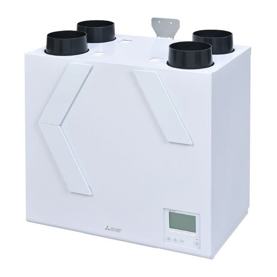
* The figure shows VL-350CZPVU-R-E
■ This product is for residential use.
■ This product must be correctly installed to ensure that its performance and functions are properly demonstrated
and to ensure its safe use and operation. Before installation, please read this installation manual thoroughly.
Before using exclusive system components, read the installation manual for the system components thoroughly.
■ For installation parts, be sure to use accessories and designated parts. Use of non-designated parts may be a
cause of malfunction.
■ Installation must be performed by dealers and electrical contractors. Incorrect installation by the customer may be
a cause of equipment malfunction or an accident.
■ Electrical work must be performed by a properly qualified electrician of the dealer or electrical contractor.
■ Please note that enough working space (remove the cover, replace the filter, etc.) is required around the product
for maintenance.
■ Install the unit indoor.
For dealer/contractor
Contents
1. Safety Precautions ..............................2
2. Outside Dimensions ...........................6
3. Standard Installation Example ............ 10
3.1 Installation example ..................... 10
3.2 Working space ........................... 11
4. Installation Procedure ........................ 12
5. Electrical Work ................................. 15
5.1 Standard use .............................. 15
5.2 External device connection use ...... 15
6. How to use Controller ........................ 17
6.1 Controller button functions .................. 17
6.2 Menu structure ................................. 18
6.3 Main menu screen and operation ......... 19
6.4 Commissioning menu ........................ 20
6.5 Function setting ................................. 12
6.6 How to(Error list) .............................. 42
6.7 Commissioning ................................. 42
7. Post-installation Checks ..................... 43
8. Trial operation ................................. 44
Eng-1
Advertisement
Table of Contents

Related Manuals for Mitsubishi Electric VL-250CZPVU-R-E


Summary of Contents for Mitsubishi Electric VL-250CZPVU-R-E
-
Page 1: Table Of Contents
LOSSNAY HEAT RECOVERY VENTILATOR (RESIDENTIAL USE) MODEL VL-250CZPVU-R-E VL-250CZPVU-L-E VL-350CZPVU-R-E VL-350CZPVU-L-E Installation Manual For dealer/contractor Contents 1. Safety Precautions …………………………2 2. Outside Dimensions ………………………6 3. Standard Installation Example ………… 10 3.1 Installation example ………………… 10 3.2 Working space ……………………… 11 4. -
Page 2: Safety Precautions
1. Safety Precautions The following symbols indicate the degree of danger caused Symbols used in the text and on the main unit have the by incorrect handling of the product. following meanings. Do not install in WARNING CAUTION Prohibited bathroom Incorrect handling of the Incorrect handling may result Do not disassemble... - Page 3 WARNING When using duct heaters (supply air preheaters, supply air after-heaters), make sure to use safety devices that do not have self-return functions. Do not supply the duct heaters with electricity directly from the product. Failure to heed this warning may result in fire. When using duct heaters (supply air preheaters, supply air after-heaters) that do not have temperature control functions, select duct heaters that have the appropriate capacity according to the airflow passing Follow through the heaters.
- Page 4 CAUTION Do not install the product at regions or locations that exceed the following operating conditions. If these operating conditions are exceeded, dew condensation water might drip. Outdoor air temperature: -15 to 40 ºC Area around the product and ambient temperature and humidity:0 to 40 ºC 80%RH or less and at absolute humidity or less where the dew point temperature of 12 ºC (20 ºC 60%RH or equivalent) is reached under the above minimum outdoor air temperature conditions When installing the product, do not drop or throw the product, or subject the product to impact.
- Page 5 Note - Do not install the product at locations where toxic gas or gas containing corrosive components such as acids, alkaline, organic solvents, or paints is generated. (Failure to heed this warning may result in malfunction.) Do not install the product near bedrooms. (Failure to heed this warning may cause complaints about noise.) - For living rooms (e.g.
-
Page 6: Outside Dimensions
2. Outside Dimensions ■VL-250CZPVU-R-E Pipe Guide (EA) Pipe Guide (RA) Pipe Guide (SA) Pipe Guide (OA) Wall Bracket (Accessory) Wall Mount Hook Top φ122 Filter Cover (OA) Filter Cover (RA) Heat exchanger Filter Cover (SA) Wall Mount Hook Down Wall Mount Hook Center Controller... - Page 7 ■VL-250CZPVU-L-E Pipe Guide (SA) Pipe Guide (OA) Pipe Guide (EA) Pipe Guide (RA) Wall Mount Hook Top Wall Bracket (Accessory) φ122 Filter Cover (RA) Filter Cover (OA) Heat exchanger Controller Wall Mount Hook Down Wall Mount Hook Center Filter Cover (SA) Drain pipe (EA) Drain pipe (SA) φ22 φ22...
- Page 8 ■VL-350CZPVU-R-E Pipe Guide (EA) Pipe Guide (RA) Pipe Guide (SA) Pipe Guide (OA) Wall Bracket (Accessory) Filter Cover (OA) Wall Mount Hook Top φ145 Filter Cover (RA) Heat exchanger Filter Cover (SA) Controller Wall Mount Hook Center Wall Mount Hook Down Cable strap hole Power Supply Cord Control box Drain pipe (SA)
- Page 9 ■VL-350CZPVU-L-E Pipe Guide (SA) Pipe Guide (OA) Pipe Guide (EA) Pipe Guide (RA) Wall Bracket Wall Mount Hook Top Filter Cover (RA) (Accessory) φ145 Filter Cover (OA) Heat exchanger Controller Wall Mount Hook Center Filter Cover (SA) Wall Mount Hook Down Drain pipe (EA) Drain pipe (SA) φ22 φ22...
-
Page 10: Standard Installation Example
3. Standard Installation Example 3.1 Installation example Note - Be sure that the exhaust air connection has two or more confluence points with the piping from the bathroom. - Preheaters and electric dampers may be required in your region. - Read the instructions carefully in advance when using optional components and commercially available components. sensor Living room OA shutter... -
Page 11: Working Space
3.2 Working space (required space around the product) This product requires regular maintenance (filter cleaning, parts replacement). Place the product from any other obstacles for maintenance. ■VL-250CZPVU-R 600≤ 500≤ Control box Space to pull out Unit (mm) ■VL-250CZPVU-L 600≤ 500≤ Control box Space to pull out Unit (mm) Note... - Page 12 ■VL-350CZPVU-R 678≤ 580≤ Control box Space to pull out ■VL-350CZPVU-L 678≤ 580≤ Control box Space to pull out Unit (mm) Note - Secure about 10 mm of clearance from the side faces of the product to any other obstacles. (If not enough clearance is secured, maintenance cannot be performed.
-
Page 13: Installation Procedure
4. Installation Procedure 4.2 Mounting the Unit WARNING Select a place which is strong enough to support the CAUTION product, and install the product securely. Do not carry with a pipe guide. Injury could result if parts fall. Failure to heed this warning may result in damage to pipe guide. - Page 14 - Before connecting the ducts, make sure that there are Indoor humidity can cause condensation because no metal chips or other foreign matter (For example exposed parts can become cold in winter. paper or vinyl) inside the ducts or inside the product. ■VL-250CZPVU-R-E ■VL-250CZPVU-R-E ■VL-250CZPVU-L-E ■VL-250CZPVU-L-E Insulating (Field supply) Duct Inner diameter φ150...
- Page 15 4.5 Connecting drain piping 4.5.1 Connection method of drain hose (EA drain pipe) CAUTION 1) Securely connect the accessary drain hose to the root of the connection port. Make sure to connect drain piping by the following procedure to prevent freezing and dew condensation Securely fix the accessory hose band by tightening with forming on the surface of the piping a flat head screwdriver. (Otherwise, water leakage can...
-
Page 16: Electrical Work
5. Electrical Work 5.2 External device connection use WARNING Connect the each cable for external devices to control board Electrical work must be carried out safely and reliably by according to the way below. a professional electrical contractor (properly qualified electrician) in accordance with internal wiring provisions 1) Remove 2 screws. Pull the control box. (It stops in the and electricalequipment technical standards. - Page 17 Diagram for control board Control circuit board Bypass monitor or Pre heater signal CN20 (GR) Malfunction monitor output CN26 (WH) Operation monitor output CN32 (WH) CN17 (RE) IT interconnection Wi-Fi Controller CN105 (RE) LED3 Printed Circuit Board (CONTROL) LED4 LED2 LED1 CN19 CN18 CN22...
-
Page 18: How To Use Controller
6. How to use Controller 6.1 Controller button functions 1 ON/OFF button Off operation is disabled at the factory default setting. Please see 6.4.2.7 Control mode. 2 SELECT button 3 RETURN button 4 MENU button The «Main menu» screen is displayed. Please see 6.2 Menu structure. 5 Backlit LCD The screen displays operation settings. -
Page 19: Menu Structure
6.2 Menu structure Main operation Main menu User options Press the button. Boost/Purge preset Move the cursor to the Silent mode desired item with the Manual bypass mode Please see Instruction manual buttons, and press the Holiday mode button. Clock Commissioning Commissioning menu (1/2) Initial setting Initial setting menu (1/2) -
Page 20: Main Menu Screen And Operation
6.3 «Main menu» screen and operation 6.3.1 Turning on the power Before turning on the power: 1) Make sure that the connection is properly installed according to the Installation Manual. 2) Make sure that the product has been installed completely. 6.3.2 When the power is supplied, the screen below will appear. - Page 21 6.4.1 Administrator password <Administrator password is required.> Press to move the cursor. Administrator password Press to change the number. Enter administrator password 0000 Press to set the password. Select: Cursor Note - The administrator password is required to set the items under «Commissioning menu». - Factory default password is 9999.
- Page 22 6.4.2.3 Contrast You can set Contrast of the screen. Press to adjust the contrast. Contrast Press to save the changes. Main menu: Light Dark Note - Adjust the contrast to improve viewing in different lighting conditions or different installation locations. This setting does not always improve the display from all directions. 6.4.2.4 Display details You can change the display details about clock and temperature, sensor value. Press to move the cursor. Display details Clock No 24h Press to change the setting.
- Page 23 Clock display Clock display Clock: Clock 12h disp. Change [Display (Yes)/Hide (No)] the time on the «Main AM/PM disp. operation» screen. The factory default setting: Yes Select: Cursor Cursor 12h display format: Change the time display [12 hour (12h)/24 hour (24h)] on the «Main operation» screen. The factory default setting: 24h AM/PM display: Only selecting [12h disp.].
- Page 24 6.4.2.7 Control mode Setting Fan speed, ventilation mode icon and limitation of function. Note - «Control mode» screen cannot be go to when the product is in operation. Press on the «Initial setting» screen to stop the operation. Press to move the cursor. Control mode Control mode Simple mode...
- Page 25 6.4.3 Air flow Adjust the output of the fan speed. Note - Make sure to set the Airflow settings for all fan speeds to be used and measure the air volumes. The output of the notch whose fan speed has been changed from the factory default setting is different from the output of the notch whose fan speed has not been changed.
- Page 26 6.4.3.4 Adjust the fan output of the product The product starts adjusting the fan output. Airflow Airflow adjusting [Airflow adjusting] is displayed. Normal Medium Skipped After completing the output adjustment of the fan on the Boost 70 % / 70 % product, it returns to the screen of 6.4.3.3. Purge 100 % / 100 % Note - Measure the air volume after Airflow adjusting has disappeared.
- Page 27 6.4.4 Auto bypass In the Auto bypass mode, the product decides to operate heat exchange ventilation/bypass ventilation every 30 minutes. On the «Auto bypass» screen, set the threshold of the switching map for heat exchange ventilation/bypass ventilation. Outside temperature, indoor temperature, and their temperature difference can be set as the threshold. Outdoor temp. low limit: The lowest limit of outdoor temperature in the bypass ventilation area The factory default setting: 16°C / Setting range: 10 to 25°C Target indoor temp.:...
- Page 28 6.4.4.1 Accessing the «Auto bypass» screen Press to move the cursor. Commissioning menu Airflow Initial setting Press to go to the next screen. Airflow Auto bypass Loading External input The product data is loaded before the screen will appear. Service [Loading] is displayed. (10-60 seconds) Main menu: Cursor...
- Page 29 6.4.5 External input The product has external input terminals. (See below.) Function name Input Terminal Analog input 1 0 -10 VDC TM200 1-2 Analog input 2 0 -10 VDC TM200 3-4 Live switch 220-240 VAC Power cable LS (Black) Volt-free contact Contact input TM201 3-4 On the «External input» screen, you can set the operation for the external input. Note - The product operates according to the highest fan speed input from the external input of the effective settings.
- Page 30 The table shows the conditions for operation patterns. concentration Remarks Pattern Input voltage [VDC] Fan speed [ppm] - Select the CO sensor whose relation between the CO concentration 0.0 -2.6 0 - 520 and the output voltage is 2000 ppm = 10 VDC. - The fan speed will be the highest if the input voltage exceeds 6.0 VDC.
- Page 31 6.4.5.3 Live switch Set the operation for the live switch input (220-240 VAC input linked with a lighting switch etc.). Connection example) Bipolar single-throw Humidity switch AC 220 - 240 V Power cord ISOLATOR Light L (Brown) N (Blue) LS (Black) Earth (Green/Yellow) CAUTION Do not connect a load such as lighting to the live switch input. It may cause product failure. Note - Since the circuit secures 30 mA when the switch is turned on, the maximum number of switches that can be used for the Live switch input is three when using the minimum load capacity of 10 mA.
- Page 32 6.4.5.4 Volt-Free contact Set the operation for Volt-free contact input (input linked with non-voltage contact etc.). Connection example) Note Switch - Since the circuit ensures 1 mA when the switch is turned Rating: 15 VDC/0. l A or more on, the maximum number of switches that can be used Min: l mA or less for Volt-Free contact input is one when the minimum load capacity is 1 mA. Press to move the cursor.
-
Page 33: Function Setting
6.4.6 Service 6.4.6.1 Accessing the «Service menu» screen Press to move the cursor. Service menu Input maintenance info. Press to go to the next screen. Function setting Initializing Service menu: Cursor 6.4.6.2 Input maintenance info. The following can be set. The information input at (1), (2), and (3) is displayed on the «Error information»... - Page 34 6.4.6.4 Initializing The setting values changed by the controller are returned to the factory default setting. Note - The «Function setting» screen will not be displayed when the product operation is not stopped. Press on the «Service menu» screen to stop the operation. Press to initialize the data.
- Page 35 Press to move to the Reset screen. Error unit Dealer M-NET address 0 Tel 012-3456-7890 Model name VL-250CZPVU-R-E Model name, Serial No. and Dealer information will Serial No. 01234567 be displayed only when they are set at 6.4.6.2. Reset error:Reset button Reset error: Reset button...
- Page 36 6.4.9 Error history You can check the past error history. Error state cannot be reset from this screen. Press to change the page. Error history Error Unt# dd/mm/yy Up to 4 pages, 12 cases can be stored in the error history. 0900 --- 20/04/10 12:34 Press to move to the Reset screen. Check menu: Page Delete Press to reset the error information. Error history Delete error history? Cancel blinks...
- Page 37 6.4.10 Run time You can check the powered time and fan operation time of the product. 6.4.10.1 Accessing the «Run time» screen Press to move the cursor. Commissioning menu Auto bypass Restriction Press to go to the next screen. Error information Error history Loading The product data is loaded before the screen will appear. Run time Maintenance interval [Loading] is displayed. (10-60 seconds)
- Page 38 6.4.11 Maintenance interval Set the maintenance interval of the filters. After the fan operation time exceeds the product maintenance Lossnay 12:30 Fri interval, the maintenance sign ( ) will be displayed on the «Main operation» screen. Boost HeatEX Mode 6.4.11.1 Accessing the «Maintenance interval» screen Press to move the cursor.
- Page 39 6.5 Function setting 6.5.1 Function setting list Factory Function setting value Function Function name default Function description [8] [9] setting 1: Set the filter maintenance indica- tion to show/hide. 2: Set Use/No use of the function 1: Filter maintenance 1: Yes 1: No 1: Yes that increases the fan output indicator − / /...
- Page 40 Factory Function setting value Function Function name default Function description [8] [9] setting Set the ON/OFF conditions of termi- nal blocks TM3 9-10. [1] Exhaust air fan The terminal blocks turn ON/OFF in line with the operation/stop of the exhaust air fan. (The terminal blocks will perform the operation which is the same as ON/OFF of the control- ler.)
- Page 41 Factory Function setting value Function Function name default Function description [8] [9] setting Set the ON/OFF conditions of termi- nal blocks TM3 8-10. [1] Malfunction monitor: Turns the output ON when a mal- function occurs on the product. (This is used to indicate malfunctions aside from the controller.) [2] Supply air shutter: Set the setting so that the output...
- Page 42 6.5.2 External output specifications WARNING Make sure to install safety devices that do not have self-return functions on the duct heaters (supply air preheaters, supply air after-heaters). Do not supply the duct heaters with electricity directly from the product. Failure to heed this warning may result in fire. When using duct heaters (supply air preheaters, supply air after-heaters) that do not have temperature control functions, select duct heaters that have the appropriate capacity according to the airflow passing through the heaters.
- Page 43 The control circuit boards of the product have external output terminals to output the product operation conditions to external devices. TM3 terminal: rated Terminal block Output Signal type (TM3) Maximum Minimum Function setting No.57, External output setting 1 9-10 (Exhaust air fan/supply air fan/supply air after-heater) Function setting No.58, External output setting 2 Volt-free 7-10...
-
Page 44: Commissioning
6.6 Error list № Error item Error code Unit operation Error code reset Description Commissioning The error is indicated when the product is in 0900 Commissioning operation End the commissioning operation in the commissioning mode. External device error The error is indicated when an abnormal temperature is detected by the built-in OA 3126 Heater output: OFF... -
Page 45: Post-Installation Checks
7. Post-installation Checks When you have finished installation work, inspect the following items according to the following check list before turning the power on. Be sure to correct any malfunctions that are found. (The functions is not being demonstrated or safety can not be ensured) Check Item Remedy for Malfunction... -
Page 46: Trial Operation
8. Trial operation After the system has been installed, make sure that cables are properly connected, then test the system’s operation. ■ Perform trial operation with the user in attendance. - Noise sometimes increases for several minutes after the power to the Lossnay unit is turned off. This is operation to maintain the ventilation air volume at the appropriate volume, and is not a malfunction. - It is difficult to tell the ventilation state when there is wind outside or during operation of a range hood fan, etc. - Page 47 ■ If trouble occurs during trial operation Symptom Remedy Check Will not operate even when • Check the power supply. (The specified power supply is single-phase 220-240 V / 50 Hz, 220 V the operation switch for the / 60 Hz) controller is pressed. • Check for a short circuit or disconnection in the transmission cable. (Check that the voltage between terminals in the transmission cables is 10 to 13 VDC for the controller.) •...
- Page 48 Explaining to the User ● Explain to the user where the circuit breaker and remote controller are located and how to clean the filters. ● Tell the user the results of checks performed using the check list. ● Hand over the customer a leaflet with the URL where this manual can be viewed. ● Explain correct use by following the descriptions in the Instruction Manual. In particular, Safety Precautions describe important notices and warnings relating to safety. Explain to users that they should observe these. HEAD OFFICE: TOKYO BLDG., 2-7-3, MARUNOUCHI, CHIYODA-KU, TOKYO 100-8310, JAPAN Eng-48...