Table of Contents
Advertisement
Chilli Pro
Introduction
Revisions
Chilli Pro Versions
Warnings & Safety
Installation
Connecting the mains
Connecting channel outputs
Connecting DMX
Alarm input
Connecting ChilliNet
User Interface
Default Screens
Menu Structure
Manual Control
Memories
Sequences
Preheat
Dimmer Laws
Topset
Reset Dimmer
DMX Controls
Security
ChilliNet
Area Control
Alarm Input
Bypass Switches
Relay Cards
Relay Card Fitting Instructions
Technical Specification
Support
Zero 88 - Chilli Pro - Page 1 of 60
Record Memory
Play Memory
Clear Memories
Edit Memory
Program Sequence
Playback Sequence
Sequence Options
Clear Sequence
Set Start Address
Set DMX Patch
Reset DMX Patch
DMX Input
RDM
Printed: 23/03/2021 09:13:40 ES
Advertisement
Table of Contents

Related Manuals for Zero88 Chilli Pro Series


Summary of Contents for Zero88 Chilli Pro Series
- Page 1 Chilli Pro Introduction Revisions Chilli Pro Versions Warnings & Safety Installation Connecting the mains Connecting channel outputs Connecting DMX Alarm input Connecting ChilliNet User Interface Default Screens Menu Structure Manual Control Memories Record Memory Play Memory Clear Memories Edit Memory Sequences Program Sequence Playback Sequence...
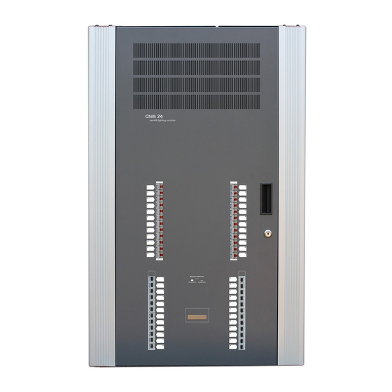
- Page 2 Today’s performance installations demand that lighting control intelligence can operate building wide. Chilli Pro have been designed from the start with this in mind and can deliver outstanding performance dimming. Chilli Pro is a range of high density wall mounted convection cooled power switching and dimming cabinets. Quick to install and set up, easy to operate and maintain;...
- Page 3 Our extensive dealer network can also provide you with technical service and sales support in your local language no matter where you are in the world. If you have any questions, comments or problems our contact details can be found zero88.com/support Once again, thank you for choosing Zero 88.
- Page 4 Zero 88 online manuals are updated regularly to ensure you have all the relevant information and useful tips. Check out the Revisions section to see what has been added. If you see something that doesn't look right, or have suggestions, please send us an email to support@zero88.com. Conventions...
- Page 5 Over the years, where possible, core parts were kept the same, and the MK1 and MK2 dimmer parts were completely interchangeable. However changes to the keypad/power PCB kits and output PCB on the MK3 are unique to this version. Identifying Chilli Pro 24 versions The simplest way to identify the dimmer type is by the configuration of the breakers as shown below: MK1 &...
-
Page 6: Warnings And Safety
Warnings & Safety Do not remove the covers without first completely disconnecting Chilli Pro from the mains supply. This product must be earthed. This equipment is designed for professional stage lighting control and is unsuitable for any other purpose. It should be used by, or under the supervision of, an appropriately qualified or trained person. -
Page 7: Installation
Installation The unit should be installed in a dry ventilated location, where ambient temperature and humidity are within the operating range of the unit. The units have ventilation slots / heatsink on all sides to allow convection cooling and under no circumstances should these be blocked. - Page 8 Chilli Pro 12 & 24 are designed to run on a nominal 230V 50Hz 3-phase supply, with a maximum 100A per phase. However, all variants of Chilli Pro without RCDs can be converted to single phase operation. This results in a total 100A maximum input.
- Page 9 Chilli Pro 12 The Chilli Pro 12 has the following knockouts: Top 2 x Ø50.0mm,1 x Ø32.0mm Bottom 2 x Ø25.5mm Appropriate cable glands should be fitted to the knockout holes provided to protect the mains cables from damage. The channel (load) cables are connected to the terminal strips located on the top right of the unit. The outputs will accept a maximum 6mm cable.
-
Page 10: Alarm Input
There is a dedicated terminal for the live and neutral of each output circuit. Channels 1 to 12 are on the left hand side, and channels 13 to 24 are on the right hand side. A shared Earth bus bar is mounted on the chassis of the dimmer for channels 1-12, and a separate bus bar for 13-24. - Page 11 Network Connection All network and control cables should enter the dimmer through the segregated route at the bottom of the dimmer. Segregation between control data cabling and power wiring should be maintained for reasons of safety and noise immunity. Control data cabling should be run in separate or divided metal trunking or conduits. Where cables are run outside trunking or conduits there should be 300mm separation between them and where they cross they should do so at right angles.
-
Page 12: User Interface
User Interface This chapter describes all the various dimmer functions, which can be adjusted using the user interface buttons, with settings and information displayed on the LCD. If ChilliNet is enabled, the LCD will be in ChilliNet mode and will display different information. Zero 88 - Chilli Pro - Page 12 of 60 Printed: 23/03/2021 09:13:40 ES... -
Page 13: Default Screens
The LCD comprises two lines of 16 characters, and shows various screens and information. Numeric Keys The numeric keys (0 - 9) are used for entering numerical data (e.g. channel number, manual levels, DMX addresses etc.) Star Key The function of the star key * is not yet defined. Hash Key The Hash key # is used to toggle the channel level between 0% and 100% in Manual Control or Edit memory. - Page 14 Standard Mode In standard mode, the LCD will show the DMX field on the top row, and the temperature status on the bottom row: DMX: 1 Temp: OK ChilliNet Mode In ChilliNet mode, the LCD will show the DMX field on the top row, and the ChilliNet field on the bottom row: DMX: 1 Chilli Net: 12 Alarm State...
- Page 15 These default screens contain three different fields; DMX, Temp and ChilliNet. These are described as follows: DMX Field in the Default Screens The DMX field in the default screen will show the status of the DMX input signal. Receiving valid DMX dimmer data: “DMX: xxx”...
-
Page 16: Menu Structure
Temp Field in the Default Screens The Temp field in the default screen will show the status of the temperature sensor. During startup the text “Temp: No Val” is shown briefly whilst the dimmer is reading the sensor. This is normal behaviour. Internal temperature sensor fault: “Temp: No Val”... -
Page 17: Manual Control
The top-level menu options are: Manual Control Memories Sequences Preheat Dimmer Laws Topset Reset Dimmer DMX Controls Security ChilliNet Area Control When there are other menu options available at the same level < and > symbols will appear at the left and right hand sides of the screen. - Page 18 The cursor is shown in the Channel field. ChilliNet mode When operating in ChilliNet mode, the screen shows: A (xx) Channel: xx Level: xxx The cursor is shown in the Channel field. The area number A(xx) shows the area that the dimmer channel is assigned to and is for information only. In both Standard and ChilliNet modes, individual channel levels can then be adjusted using the numeric keypad or cursor keys.
- Page 19 Area: 1 Level: 0 The cursor is in the Area field. Press the ENT key to move between the Area and Level fields. The area number must be valid (i.e. the dimmer has one or more channels assigned to that area) to adjust the Level field. Memories The Chilli Dimmer can be programmed with up to 12 memories.
- Page 20 The cursor appears in the memory number field (xx). Unprogrammed memories are indicated by an ‘*’ next to the memory number. Use the numeric keypad or cursor keys to select the required memory (1 - 12). Press the ENT key to confirm the memory selection. The screen shows: Memory: xx Fade Time: xx The Memory field is for information only and is not editable.
- Page 21 The Area and Mem fields are for information only. The cursor appears in the Fade Time field. Use the numeric keypad or cursor keys to adjust the fade time as required (1 - 60 seconds). Press the ENT key to save the fade time to the memory. The dimmer will then grab the current output levels for the selected area and store them in the selected memory.
-
Page 22: Clear Memories
Area: 1 Memory: xx The cursor is in the Area field. Enter the required area number using the numeric keypad or cursor keys, then press the ENT key. If the area number is valid, the cursor moves to the Memory field. If a memory for the selected area is currently being output from the dimmer, then that number is shown. - Page 23 ChilliNet Mode This option allows you to clear all the 12 memories for a specified area in the dimmer. Select the Clear Memories option from the Memories menu, and press the ENT key. The screen shows: Area: 1 ENT to clear The cursor appears in the Area field.
- Page 24 The cursor is shown in the Channel field. The Level field shows the programmed value for the channel. Adjust the level of each channel as required. This operation uses the same user interface as the Set Channel Level function in Manual Control. Press the ESC key.
- Page 25 The area number field A(xx) is for information only. The cursor is shown in the Channel field. The Level field shows the programmed value for that channel in the memory. Adjust the level of each channel as required. This operation uses the same user interface as the Set Channel Level function in Manual Control.
-
Page 26: Program Sequence
Click the available options to find out more... Program Sequence Playback Sequence Sequence Options Clear Sequence Program Sequence Standard Mode This option allows you to program one of the three sequences, using the programmed memories in the dimmer. Select the Program Sequence option from the Sequences menu, and press the ENT key, the screen shows: Select Sequence: 1 Use the numeric or cursor keys to select the required sequence number, then press the ENT key. - Page 27 ChilliNet Mode This option allows you to program any of the three sequences in the dimmer with memories for a specific area. Select the Program Sequence option from the Sequences menu, and press the ENT key. The screen shows: Sequence: 1 (Axx) Area: 1 The cursor appears in the Sequence field.
- Page 28 Sequence: 1 ENT to start If sequence X is currently running in the dimmer, the screen shows: Sequence: X ENT to stop Use the cursor keys to select the required sequence. The second line of the screen shows the current state of the selected sequence. Starting a Sequence Select the required sequence using the cursor keys, then press the ENT key.
- Page 29 Sequence: X ENT to stop Use the cursor keys to select the required sequence. The second line of the screen shows the current state of the selected sequence. Starting a Sequence Select the required sequence using the cursor keys, then press the ENT key. The sequence will start running.
-
Page 30: Clear Sequence
The cursor appears in the X-Fade Time field. Use the numeric keypad or cursor keys to adjust the fade time as required (range 1 - 60 seconds). Press the ENT key to confirm the crossfade time. The cursor moves to the Dwell Time field. Use the numeric keypad or cursor keys to adjust the dwell time as required (range 1 - 600 seconds). - Page 31 Channel: xx Level: xx The cursor is shown in the Channel field. Press the ENT key to move between the Channel and Level fields, and adjust the values using the numeric keypad or cursor keys. Clear Preheats This option allows you to clear the preheat levels for all of the dimmer channels to 0%. Select the Clear Preheats option from the menu, and press the ENT key.
- Page 32 Linear - Suitable for most live or theatrical situations. Switch - Output switches from zero to full when the input reaches 50% (DMX slot value of 128). Square - For use with video cameras. Non-dimmable loads should NOT be connected to Chilli Pro dimmer channel outputs, without the use of the bypass switch being pressed on bypass variants.
- Page 33 The cursor is shown in the Channel field. The channel is selected using the numeric keypad or cursor keys. Press the ENT key to move between the Channel and Law fields. When the cursor is in the Law field, the cursor keys cycle through the laws. The currently selected law for the channel is indicated by a ‘*’, for example: Channel: 10 Law: Normal*...
- Page 34 Set Topset This option allows you to set up a topset level (between 0 - 100%) for each of the dimmer channels. Select the Set Topset option from the menu, and press the ENT key. The screen shows: Channel: xx Level: xx The cursor is shown in the Channel field.
-
Page 35: Dmx Controls
This option allows you to reset the dimmer to its default settings which are defined as follows: All Triac dimming laws set to Normal. All Relay dimming laws set to Switched. Preheat for all channels off (0%). All memories cleared. All memory fade times reset to 3s. - Page 36 Click the available options to find out more... Set Start Address Set DMX Patch Reset DMX Patch DMX Input Set Start Address This option allows you to set a DMX start address for the dimmer. The dimmer channels are then patched automatically as a contiguous block starting at the specified address. Select the Set Start Address option from the menu, and press the ENT key.
-
Page 37: Dmx Input
The cursor appears in the Channel field. Press the ENT key to move between the Channel and DMX fields, and adjust the values using the numeric keypad or cursor keys. Reset DMX Patch This option allows you to reset the start DMX address for the dimmer to DMX channel 1. Select the Reset DMX Patch option from the menu, and press the ENT key. - Page 38 This option allows you to enable or disable the DMX input signal to the dimmer without having to physically disconnect the DMX cable. When the DMX input is enabled, you can choose between two modes of operation - HTP mixing or DMX takes precedence.
- Page 39 DMX FAIL MODE < Hold DMX > Select the required DMX fail Mode as follows: Hold DMX - Use cursor keys to select this option. Press the ENT key. Fade to Black - Use cursor keys to select this option. Press the ENT key. Fade to Memory - Use cursor keys to select this option.
- Page 40 This screen allows you to turn the selected DMX Input Mode on or off for each area defined on the dimmer. The cursor is shown in the Area field. Use the numeric keypad or cursor keys to select an area, then press the ENT key.
- Page 41 DMX Fail Modes Hold DMX In HTP Mix mode, the last DMX input levels are held in the dimmer and mixed in as normal. In DMX Precedence mode, the DMX inputs are removed from the output calculations. Fade To Black The DMX Input values and any memory or sequence being output are faded to black (0%) over 3 seconds.
- Page 42 Use the cursor keys to alter this setting between On and Off, to enable or disable the DMX RDM (Remote Device Management) functionality of the Chilli Dimmer. RDM Support The first 5 digits of the part number are used for the Device Model ID., e.g. 01105 (0x0451) for the Chilli Pro 1210. Supported Parameters: DMX_START_ADDRESS, SENSOR_DEFINITION,...
- Page 43 Lock Dimmer Code: xxxx Use the numeric keypad to enter a 4 digit code and then press the ENT key. The screen shows: Confirm Code Code: xxxx Re-enter the same 4 digit code and then press the ENT key to confirm. If the codes match - the dimmer is locked, the screen returns to the main screen, and all menu access is disabled.
-
Page 44: Area Control
State: Disabled Dimmer No: xxx The cursor is in the State field. Use the cursor keys to select Enabled. Press the ENT key to move the cursor to the Dimmer No field: State: Enabled Dimmer No: xxx Enter the dimmer number using the numeric keypad or cursor keys. Press the ENT key to confirm. The dimmer number is checked against other dimmers on the network. - Page 45 This option is only available when the dimmer is in ChilliNet mode. This option allows you to assign each of the dimmer channels to an Area (1 - 10). Select the Area Control option from the top level menu options, and press the ENT key to enter the Area Control menu.
- Page 46 The Chilli Dimmer has an alarm input, which when activated, causes it to enter an alarm state. If the dimmer is connected to ChilliNet, it will also send out alarm messages to ensure that all other devices on the network also enter the alarm state. Alarm Input Active When the dimmer’s Alarm Input is activated, the following will occur: The dimmer enters the Alarm State.
- Page 47 Alarm Off Message When a networked dimmer receives an Alarm Off message and its Alarm Input is not active, the following will occur: The dimmer exits the Alarm State. All output channels fade to their normal levels over a period of 1s. All menu access via the control panel is enabled.
-
Page 48: Bypass Switches
Bypass Switches Chilli Pro dimmers are available in variants with bypass switches per channel. With bypass variants, a dedicated bypass switch per channel is provided on the front of the Chilli Pro. When a bypass switch is pressed in for a channel, the supply to the channel output bypasses the dimming circuitry, and is fed from the mains supply. -
Page 49: Relay Cards
0095-000108-00 - Primary Relay Card & PSU Kit 0095-000109-00 - Secondary Relay Card Kit To confirm your version of Chilli dimmer, see the link below... https://zero88.com/manuals/chillipro/introduction-105/chilli-pro-versions Chilli Channel Outputs Zero 88 - Chilli Pro - Page 49 of 60 Printed: 23/03/2021 09:13:40 ES... - Page 50 Ensure the power supply to the dimmer is isolated before commencing this procedure. Observe precautions for handling Electrostatic Sensitive Devices Zero 88 - Chilli Pro - Page 50 of 60 Printed: 23/03/2021 09:13:40 ES...
- Page 51 Instructions for Chilli Pro MK3 Configure Relay Channels 1 . Prior to fitting the relay cards, configure the channels you wish to convert to relays in the dimmer settings. Usingthe User Interface: 1. Press Enter to get to the Menu 2.
- Page 52 4 . For non-bypass variants, the PSU can be fitted at the top of the DIN rail where the Bypass switches would be fitted. 5 . Screw the other end of the brown Live wire into the first circuit breaker. Screw the other end of the blue Neutral wire into the first circuit breaker.
- Page 53 Reassembly 16 . Refit all covers, reusing the screws that have been retained. If you hear a relay buzzing, the channel dimmer law hasn’t been set to Switch. See step 1. Instructions for Chilli MK1 & MK2 Configure Relay Channels 1 .
- Page 54 5 . Screw the other end of the brown Live wire into the first circuit breaker. Screw the other end of the blue Neutral wire into: 1. One of the Neutral DIN terminal blocks if a non-RCD version Chilli 2. The phase one RCD if the Chilli has RCDs fitted Zero 88 - Chilli Pro - Page 54 of 60 Printed: 23/03/2021 09:13:40 ES...
- Page 55 Removal of Triac Boards 6 . Unscrew the Triac connectors on the boards to be replaced from the left-hand side of the unit. 7 . Working through each individual channel to be replaced, cut the cable ties on the Live and Load wires. Disconnect each wire, untangle any wires that are twisted together (as you may need the length later) and mark up where the wire came from.
- Page 56 If you hear a relay buzzing, the channel dimmer law hasn’t been set to Switch. See step 1. Doc. No. 9850-000377-00 Zero 88 - Chilli Pro - Page 56 of 60 Printed: 23/03/2021 09:13:40 ES...
-
Page 57: Technical Specification
Technical Specification Electrical Mechanical Environmental Electrical Supply Voltage: 230V +10% / -15% Supply Frequency: 45 to 65Hz Maximum Supply Current: 12 Channel 10A: 120A / 40A per phase 3 phase star 12 Channel 16A: 192A / 64A per phase 3 phase star 24 Channel 10A: 240A / 80A per phase 3 phase star 24 Channel 16A: 384A / 128A per phase 3 phase star Channel Capacity... - Page 58 USITT DMX512/1990 Ground referenced receiver Internal switchable termination Mechanical Chilli Pro 12 Height: 1000mm Width: 400mm Depth: 155mm Weight: 24kg (max) IP Rating: IP2X (indoor use only) Chilli Pro 24 Height: 1000mm Width: 632mm Depth: 155mm Weight: 50kg (max) IP Rating: IP2X (indoor use only) Environmental Operating Temperature Range: +5°C to +40°C Operating Relative Humidity: 5% to 95% Non-condensing...
- Page 59 Emissions: EN55015 : 2000 +A1 : 2001 +A2 : 2002 Immunity: EN61000-6-1 : 2001 EN61000-6-3 : 2001 Electrical Safety: EN60950-1 : 2002 Zero 88 - Chilli Pro - Page 59 of 60 Printed: 23/03/2021 09:13:40 ES...
- Page 60 Support Support requests can be submitted via email to support@zero88.com or through our support forum at zero88.com/forum For more urgent requests, please contact Zero 88 by telephone on +44 (0)1633 838088 – 24 hour answer service available. Zero 88 - Chilli Pro - Page 60 of 60...
Need help?
Do you have a question about the Chilli Pro Series and is the answer not in the manual?
Questions and answers