Advertisement
Table of Contents
- 1 Table of Contents
- 2 Cosec Argo
- 3 What Your Package Contains
- 4 Preparation for Installation
- 5 Installation Instruction: Wall Mounting
- 6 Installation Instruction: Flush Mounting
- 7 Connecting the Cables
- 8 Configuring the Settings from ARGO
- 9 Configuring the Settings from ARGO Web Page
- 10 Technical Specification
- Download this manual
Contents
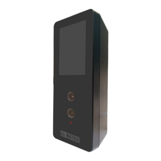
Know your COSEC ARGO
Please read this guide first for correct installation and retain
it for future reference. The information in this guide has been
authenticated at the time of publication. However, Matrix
Comsec reserves the right to make changes in product
design and specifications without prior notice.
3
7
7
9
15
21
24
29
33
2
Advertisement
Table of Contents

Related Manuals for Matrix COSEC ARGO


Summary of Contents for Matrix COSEC ARGO
-
Page 1: Table Of Contents
Please read this guide first for correct installation and retain it for future reference. The information in this guide has been authenticated at the time of publication. However, Matrix Comsec reserves the right to make changes in product design and specifications without prior notice. - Page 2 Know your COSEC ARGO Figure 3: Rear View The COSEC ARGO is available in three different variants as follows: 1) COSEC ARGO FACEE 2) COSEC ARGO FACEM 3) COSEC ARGO FACEI Figure 1: Front View Touch Screen Display RGB Camera...
- Page 3 Pre-Installation Safety Instruction Figure 6 1. Do not install the device in extremely hot temperature or under direct Sunlight on turnstile or at extra bright places. This may affect the LCD and Camera sensor of device. You can do indoor installation or on the turnstile under the roof as shown in Figure 4.
-
Page 4: Cosec Argo
The connection of EM Lock must be done using the diode for Back Preparation for Installation EMF protection. Before Wall Mounting and Flush Mounting of COSEC ARGO follow below instructions. Remove the mounting screw from mounting screw hole at the bottom •... -
Page 5: Installation Instruction: Wall Mounting
Installation Instruction: Wall Mounting Step 2: Drill the screw holes along the traced markings. Fix Wall Mounting plate with the supplied screws. Tighten the screws with a screw driver. Step 1: Place the Wall Mounting plate and trace screw holes 1 and 2 on the wall where the device is to be installed. - Page 6 Step 3: Connect the cables of the COSEC ARGO unit and lead all Keep all the cables parallel to the side of the COSEC ARGO • the cables through the duct of the Wall Mounting plate into the body in such a way that it should not cover the back electrical box recessed in the wall i.e.
- Page 7 Step 4: Align COSEC ARGO on the mounting plate and hook Step 5: Insert the mounting screw into the mounting screw hole it into the mounting slot. Press the bottom side inwards to lock at the bottom of the device. Tighten the screw to complete the it in place.
-
Page 8: Installation Instruction: Flush Mounting
Installation Instruction: Flush Mounting Step 2: Place and fix the Flush Mounting plate with the supplied screws. Tighten the screws with a screw driver. Step 1: Place the Flush Mounting Template on the desired installation surface. Figure 9 Mark the area along the dotted line and trace the four screw •... - Page 9 Step 3: Connect the cables of the COSEC ARGO unit and lead Keep all the cables parallel to the side of the COSEC ARGO • all the cables through the Flush Mounting plate into the FACE body in such a way that it should not cover the back electrical box recessed in the wall.
- Page 10 Step 5: Insert the mounting screw into the mounting screw hole Step 4: Align COSEC ARGO with the Flush Mounting plate and hook it into the mounting slot. Press the bottom side at the bottom of the device. Tighten the screw to complete the Flush Mounting.
-
Page 11: Connecting The Cables
EM Lock Cable Ethernet Cable Connect the Power, External Reader and EM Lock cable • assemblies to the 20 PIN connector affixed on the back side of the COSEC ARGO Unit. Connect the Ethernet Cable to the LAN port. • Power Cable Connect the micro USB port to the Printer or Broadband •... -
Page 12: Configuring The Settings From Argo
Diode Connection for Back EMF Protection Configuring the Settings from ARGO FACE Assigning IP/ Server Address to Device (For first time user only) Relay Relay Pin 1 Pin 2 Cathode Power Lock Anode Reverse biased Diode Connect the Overswing diode in reverse biased condition •... - Page 13 Setting the Device and Server Address from Menu Figure 23: Tap Admin Figure 24: Tap Settings Figure 21: Tap Menu Figure 22: Enter Password If you are logging in for the first time, you need to set the Password in Choose New Password and confirm the same in Confirm New Password.
- Page 14 Checking the Connectivity Status Device is Connected Device is Disconnected Figure 27: Tap Server Figure 28: Set the Server Configurations (COSEC CENTRA) In case of COSEC VYOM Figure 31: Tap About Device Figure 32: Tap Connectivity Figure 29: Select Server as VYOM Figure 30: Set the Server Configurations (COSEC VYOM) Figure 33: Connectivity Status...
-
Page 15: Configuring The Settings From Argo Web Page
Make sure the Monitor Service is running. Configuring the Settings from ARGO FACE Web Page Open the Web Browser in your computer. • Enter the IP Address of the COSEC ARGO, • default: http://192.168.50.1 in the address bar of the browser and press the Enter key on your computer keyboard. - Page 16 Figure 36 Figure 37 For COSEC VYOM Enter the Tenant ID, for example see Figure 37. • Click the Submit button, the Web Server URL (Address) and • Directory Name will be fetched automatically from the Server which cannot be modified, see Figure 37.
-
Page 17: Technical Specification
Technical Specification Technical Specification Event Buffer 5,00,000 Built In WiFi Yes (IEEE 802.11 b/g/n) Input Power 12V DC @2A and PoE Built In Bluetooth Credential Face, PIN, Card, BLE Support Built In USB Reader Power Max 12V DC @0.250A Operating 0 °C to +50 °C Output Temperature... - Page 18 If you are unable to dispose-off the products or unable to locate harmful interference when the equipment is operated in a commercial environment. e-waste recyclers, you may return the products to Matrix Return Material Authorization (RMA) department. This equipment generates, uses and can radiate radio frequency energy and, if not installed and used in accordance with the instruction manual, may cause harmful interference to radio communications.
- Page 19 2. This equipment complies with RF radiation exposure limits set forth for an uncontrolled environment. 3.This equipment should be installed and operated with minimum distance 20cm between the radiator& your body. MATRIX COMSEC PVT. LTD. Head Office 394-GIDC, Makarpura, Vadodara, Gujarat, 390010, India Ph: (+91)1800-258-7747 Email: Support@MatrixComSec.com...
Need help?
Do you have a question about the COSEC ARGO and is the answer not in the manual?
Questions and answers